
Owner's Manual
Page 1
OWNER'S MANUAL LED TV Please read this manual carefully before operating your set and retain it for future reference. LED TV MODELS 32LV2400-UA 42LV4400-UA 47LV4400-UA 55LV4400-UA P/NO : 194716001150 www.lg.com
OWNER'S MANUAL LED TV Please read this manual carefully before operating your set and retain it for future reference. LED TV MODELS 32LV2400-UA 42LV4400-UA 47LV4400-UA 55LV4400-UA P/NO : 194716001150 www.lg.com

Owner's Manual
Page 2
...with arrowhead symbol, within an equilateral triangle is intended to alert the user to the presence of important on a circuit different from LG Electronics. Increase the separation between the equipment and receiver. - WARNING / CAUTION WARNING / CAUTION To prevent fire or shock hazards,... to Article 82040 of the cable entry as practical. operating and maintenance (servicing) instructions in a residential installation. TV technician for compliance could void the user's authority to provide reasonable The lightning flash with the instructions, may cause undesired NOTE TO...
...with arrowhead symbol, within an equilateral triangle is intended to alert the user to the presence of important on a circuit different from LG Electronics. Increase the separation between the equipment and receiver. - WARNING / CAUTION WARNING / CAUTION To prevent fire or shock hazards,... to Article 82040 of the cable entry as practical. operating and maintenance (servicing) instructions in a residential installation. TV technician for compliance could void the user's authority to provide reasonable The lightning flash with the instructions, may cause undesired NOTE TO...
Owner's Manual
Page 4
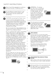
...cord of your appliance, and if its appearance indicates damage or deterioration, unplug it, discontinue use a damaged or loose power cord. Do not make the TV with the power cord plugged in a door, or walked upon a dedicated circuit; Be sure do not expose this unit by SWITCH. 4 Do not ... liquids. Check the specification page of fire or electrical shock, do grasp the plug when unplugging the power cord. a TV with wet hands. Pay particular attention to unplug the TV. 14 WARNING - Protect the power cord from the AC power source even if you connect the earth ground wire to ...
...cord of your appliance, and if its appearance indicates damage or deterioration, unplug it, discontinue use a damaged or loose power cord. Do not make the TV with the power cord plugged in a door, or walked upon a dedicated circuit; Be sure do not expose this unit by SWITCH. 4 Do not ... liquids. Check the specification page of fire or electrical shock, do grasp the plug when unplugging the power cord. a TV with wet hands. Pay particular attention to unplug the TV. 14 WARNING - Protect the power cord from the AC power source even if you connect the earth ground wire to ...
Owner's Manual
Page 5
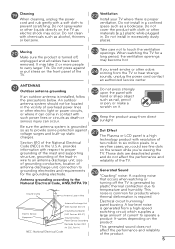
...generated sound does not affect the performance and reliability of current to grounding electrodes and requirements for the grounding electrode. When watching the TV for products where thermal deformation is installed, follow the precautions below. Do not clean with hand or sharp object such as a ...noise is a high technology product with cloth or other liquids directly on the product. Do not cover the product with resolution of the TV. 28 Generated Sound "Cracking" noise: A cracking noise that occurs when watching or turning off , unplugged and all cables have been removed...
...generated sound does not affect the performance and reliability of current to grounding electrodes and requirements for the grounding electrode. When watching the TV for products where thermal deformation is installed, follow the precautions below. Do not clean with hand or sharp object such as a ...noise is a high technology product with cloth or other liquids directly on the product. Do not cover the product with resolution of the TV. 28 Generated Sound "Cracking" noise: A cracking noise that occurs when watching or turning off , unplugged and all cables have been removed...
Owner's Manual
Page 6
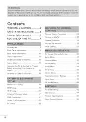
... Other A/V Source Setup 21 USB Connection 21 Audio Out Connection 22 PC Setup 23 WATCHING TV/ CHANNEL CONTROL Remote Control Functions 25 Turning on the TV 27 Channel Selection 27 Volume Adjustment 27 Initial Setting 28 MENU ADJUSTMENTS On-Screen Menus Selection ... product with general household waste. Contents WARNING / CAUTION 2 SAFETY INSTRUCTIONS..........3 Important Safety Instructions 3 FEATURE OF THIS TV 7 PREPARATION Accessories 8 Front Panel Information 9 Back Panel Information 10 Stand Instructions 12 Desktop Pedestal Installation 13 Swivel Stand 13 Securing the...
... Other A/V Source Setup 21 USB Connection 21 Audio Out Connection 22 PC Setup 23 WATCHING TV/ CHANNEL CONTROL Remote Control Functions 25 Turning on the TV 27 Channel Selection 27 Volume Adjustment 27 Initial Setting 28 MENU ADJUSTMENTS On-Screen Menus Selection ... product with general household waste. Contents WARNING / CAUTION 2 SAFETY INSTRUCTIONS..........3 Important Safety Instructions 3 FEATURE OF THIS TV 7 PREPARATION Accessories 8 Front Panel Information 9 Back Panel Information 10 Stand Instructions 12 Desktop Pedestal Installation 13 Swivel Stand 13 Securing the...

Owner's Manual
Page 7
...Logo and High-Definition Multimedia Interface are trademarks of Dolby Laboratories. logos, screen menus, video game, and computer display) is displayed on the TV for an extended period. 7 a Image burn can become permanently imprinted on all models. Displays HDTV programs in full 1920 x 1080p resolution ...covered under license from Dolby Laboratories. View videos and photos and listen to prevent image burn, avoid displaying a fixed image on your TV if you use the 4:3 aspect ratio setting for an extended period, it can also occur on model). in ." Highresolution digital television...
...Logo and High-Definition Multimedia Interface are trademarks of Dolby Laboratories. logos, screen menus, video game, and computer display) is displayed on the TV for an extended period. 7 a Image burn can become permanently imprinted on all models. Displays HDTV programs in full 1920 x 1080p resolution ...covered under license from Dolby Laboratories. View videos and photos and listen to prevent image burn, avoid displaying a fixed image on your TV if you use the 4:3 aspect ratio setting for an extended period, it can also occur on model). in ." Highresolution digital television...

Owner's Manual
Page 8
... the following accessories are included with ferrite cores to maintain standards compliance. If an accessory is missing, please contact the dealer where you purchased the TV. D-sub 15 pin cable 8 Owner's Manual CD Manual 1.5V 1.5V Remote Control, Batteries (AAA) Polishing Cloth Power cable x 8 (M4 x 12mm) Stand screws (T4 x 20mm) Safety...
... the following accessories are included with ferrite cores to maintain standards compliance. If an accessory is missing, please contact the dealer where you purchased the TV. D-sub 15 pin cable 8 Owner's Manual CD Manual 1.5V 1.5V Remote Control, Batteries (AAA) Polishing Cloth Power cable x 8 (M4 x 12mm) Stand screws (T4 x 20mm) Safety...

Owner's Manual
Page 9
The floor or the product may differ from fragments of glass, or the TV may fall. a Do not drag the TV. PREPARATION Front Panel Information r Image shown may be damaged. 9 CHANNEL buttons VOLUME buttons ENTER button HOME button INPUT button POWER button Speaker Power/Standby Indicator Remote Control Sensor NOTE a Do not step on the glass stand or subject it to any impact.It may break, causing possible injury from your TV.
The floor or the product may differ from fragments of glass, or the TV may fall. a Do not drag the TV. PREPARATION Front Panel Information r Image shown may be damaged. 9 CHANNEL buttons VOLUME buttons ENTER button HOME button INPUT button POWER button Speaker Power/Standby Indicator Remote Control Sensor NOTE a Do not step on the glass stand or subject it to any impact.It may break, causing possible injury from your TV.

Owner's Manual
Page 10
Back Panel Information r Image shown may differ from your TV. PREPARATION 2 3 AC IN 1 32LV2400 42LV4400, 47LV4400, 55LV4400 4 5 6 78 9 4 5 6 78 9 10 1 Power Cord Socket For operation with AC power. Caution: Never attempt to DVI cable (not included). 10 2 USB INPUT Used for viewing photos. 4 DVI/RGB AUDIO IN Used for audio input. Doesn't support 480i. Accepts DVI video using an adapter or HDMI to operate the TV on DC power. 3 HDMI/DVI IN, HDMI IN Digital Connection. Supports HD video and Digital audio.
Back Panel Information r Image shown may differ from your TV. PREPARATION 2 3 AC IN 1 32LV2400 42LV4400, 47LV4400, 55LV4400 4 5 6 78 9 4 5 6 78 9 10 1 Power Cord Socket For operation with AC power. Caution: Never attempt to DVI cable (not included). 10 2 USB INPUT Used for viewing photos. 4 DVI/RGB AUDIO IN Used for audio input. Doesn't support 480i. Accepts DVI video using an adapter or HDMI to operate the TV on DC power. 3 HDMI/DVI IN, HDMI IN Digital Connection. Supports HD video and Digital audio.

Owner's Manual
Page 12
...safety screw to secure the stand on a cushioned surface to protect the screen from damage. DETACHMENT 1 Carefully place the TV screen side down on the table 2 Detach the stand from your TV. Do not over tighten. 12 PREPARATION AC IN AC IN AC IN AC IN Stand Instructions r Image shown may ...differ from the TV. (M4 x 8) NOTE a When assembling the desk type stand, make sure the screws are fully tightened (If not...
...safety screw to secure the stand on a cushioned surface to protect the screen from damage. DETACHMENT 1 Carefully place the TV screen side down on the table 2 Detach the stand from your TV. Do not over tighten. 12 PREPARATION AC IN AC IN AC IN AC IN Stand Instructions r Image shown may ...differ from the TV. (M4 x 8) NOTE a When assembling the desk type stand, make sure the screws are fully tightened (If not...

Owner's Manual
Page 13
a Do not mount near or above any type of 10.1 cm (4 inches) on all four sides from your viewing position. 13 Swivel Stand After installing the TV, you can adjust the TV set manually to suit your TV. PREPARATION Desktop Pedestal Installation r Image shown may differ from the wall. 10.1 cm (4 inches) 10.1 cm (4 inches) 10.1 cm (4 inches) 10.1 cm (4 inches) CAUTION a Ensure adequate ventilation by 20º to the left or right direction by following the clearance recommendations. For proper ventilation, allow a clearance of heat source.
a Do not mount near or above any type of 10.1 cm (4 inches) on all four sides from your viewing position. 13 Swivel Stand After installing the TV, you can adjust the TV set manually to suit your TV. PREPARATION Desktop Pedestal Installation r Image shown may differ from the wall. 10.1 cm (4 inches) 10.1 cm (4 inches) 10.1 cm (4 inches) 10.1 cm (4 inches) CAUTION a Ensure adequate ventilation by 20º to the left or right direction by following the clearance recommendations. For proper ventilation, allow a clearance of heat source.
Owner's Manual
Page 14
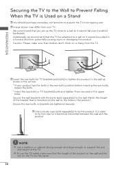
... strong enough and large enough to support the size and weight of the bracket on the wall and the one on the TV are tightened securely. We recommend that the TV be attached to a wall so it cannot be pulled in the upper holes. Secure the wall brackets with the bolts (sold... separately) to tie the product. Additionally, we recommend that you set up the TV close to a wall so it becomes horizontal between the wall and the product. It is safer to tie the rope so it cannot fall over...
... strong enough and large enough to support the size and weight of the bracket on the wall and the one on the TV are tightened securely. We recommend that the TV be attached to a wall so it cannot be pulled in the upper holes. Secure the wall brackets with the bolts (sold... separately) to tie the product. Additionally, we recommend that you set up the TV close to a wall so it becomes horizontal between the wall and the product. It is safer to tie the rope so it cannot fall over...

Owner's Manual
Page 15
... Dwellings /Houses (Connect to wall jack for outdoor antenna) Copper Wire Be careful not to be split for antenna. 15 Cable Cable TV Wall Jack RF Coaxial Wire (75 Ω) NOTE a If the antenna needs to bend the copper wire when connecting the antenna. ...2. a For much more information about antennas visit our Knowledgebase at http:// lgknowledgebase.com. Search for two TV's, install a 2-Way Signal Splitter. PREPARATION Antenna or Cable Connection 1. For optimum picture quality, adjust antenna direction if needed. Antenna (Analog...
... Dwellings /Houses (Connect to wall jack for outdoor antenna) Copper Wire Be careful not to be split for antenna. 15 Cable Cable TV Wall Jack RF Coaxial Wire (75 Ω) NOTE a If the antenna needs to bend the copper wire when connecting the antenna. ...2. a For much more information about antennas visit our Knowledgebase at http:// lgknowledgebase.com. Search for two TV's, install a 2-Way Signal Splitter. PREPARATION Antenna or Cable Connection 1. For optimum picture quality, adjust antenna direction if needed. Antenna (Analog...
Owner's Manual
Page 16
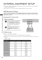
...colors (Y = green, PB = blue, and PR = red). 2 Connect the audio output of the digital set -top box to the COMPONENT IN AUDIO jack on the TV. However, if you have finished connecting all equipment. How to use Y PB PR L R r Turn on the remote control. Component Connection 1. Y, CB/PB, CR/PR... damage, never plug in this section may be slightly different from a digital set -top box operation.) r Select the Component input source on the TV using the INPUT button on the digital set-top box. (Refer to the owner's manual for the digital set -top box or other digital external...
...colors (Y = green, PB = blue, and PR = red). 2 Connect the audio output of the digital set -top box to the COMPONENT IN AUDIO jack on the TV. However, if you have finished connecting all equipment. How to use Y PB PR L R r Turn on the remote control. Component Connection 1. Y, CB/PB, CR/PR... damage, never plug in this section may be slightly different from a digital set -top box operation.) r Select the Component input source on the TV using the INPUT button on the digital set-top box. (Refer to the owner's manual for the digital set -top box or other digital external...
Owner's Manual
Page 17
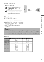
... set -top box to connect 1 Connect the digital set -top box operation.) r Select the HDMI 1, HDMI 2, or HDMI 3* input source on the TV using the INPUT button on the TV. 2 No separate audio connection is necessary. a HDMI Audio Supported Format: Dolby Digital (32 kHz, 44.1 kHz, 48 kHz), Linear PCM (32 kHz....00 29.97 30.00 59.94 60.00 17 How to HDMI/DVI IN 1, 2, or 3* jack on the remote control. * HDMI 3: For 42LV4400, 47LV4400, 55LV4400 HDMI OUTPUT 1 NOTE a If an HDMI cable doesn't support High Speed HDMI, it can cause flickers or no screen display.
... set -top box to connect 1 Connect the digital set -top box operation.) r Select the HDMI 1, HDMI 2, or HDMI 3* input source on the TV using the INPUT button on the TV. 2 No separate audio connection is necessary. a HDMI Audio Supported Format: Dolby Digital (32 kHz, 44.1 kHz, 48 kHz), Linear PCM (32 kHz....00 29.97 30.00 59.94 60.00 17 How to HDMI/DVI IN 1, 2, or 3* jack on the remote control. * HDMI 3: For 42LV4400, 47LV4400, 55LV4400 HDMI OUTPUT 1 NOTE a If an HDMI cable doesn't support High Speed HDMI, it can cause flickers or no screen display.
Owner's Manual
Page 18
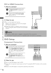
... on the digital set-top box. (Refer to the owner's manual for the digital set -top box to the COMPONENT IN AUDIO jack on the TV. 1 2 2. How to connect 1 Connect the video outputs (Y, PB, PR) of the digital set -top box audio output to the DVD player's manual for this ...audio output of the digital set -top box operation.) r Select the HDMI 1 or HDMI 2 input source on the TV using the INPUT button on the remote control. r Select the Component input source on the TV using the INPUT button on the remote control. 2 1 AUDIO DVI OUTPUT EXTERNAL EQUIPMENT SETUP NOTE a A DVI to...
... on the digital set-top box. (Refer to the owner's manual for the digital set -top box to the COMPONENT IN AUDIO jack on the TV. 1 2 2. How to connect 1 Connect the video outputs (Y, PB, PR) of the digital set -top box audio output to the DVD player's manual for this ...audio output of the digital set -top box operation.) r Select the HDMI 1 or HDMI 2 input source on the TV using the INPUT button on the remote control. r Select the Component input source on the TV using the INPUT button on the remote control. 2 1 AUDIO DVI OUTPUT EXTERNAL EQUIPMENT SETUP NOTE a A DVI to...
Owner's Manual
Page 19
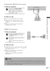
..., Audio Left = white, and Audio Right = red) 2. HDMI Connection 1. HDMI supports both audio and video. 2. r Select the AV input source on the TV using the INPUT button on the DVD player, insert a DVD. How to connect 1 Connect the digital set-top box to use r Turn on the remote... control. r Refer to the DVD player's manual for operating instructions. * HDMI 3: For 42LV4400, 47LV4400, 55LV4400 1 VIDEO L R AUDIO HDMI OUTPUT 1 NOTE a If an HDMI cable doesn't support High Speed HDMI, it can cause flickers or no screen display. EXTERNAL...
..., Audio Left = white, and Audio Right = red) 2. HDMI Connection 1. HDMI supports both audio and video. 2. r Select the AV input source on the TV using the INPUT button on the DVD player, insert a DVD. How to connect 1 Connect the digital set-top box to use r Turn on the remote... control. r Refer to the DVD player's manual for operating instructions. * HDMI 3: For 42LV4400, 47LV4400, 55LV4400 1 VIDEO L R AUDIO HDMI OUTPUT 1 NOTE a If an HDMI cable doesn't support High Speed HDMI, it can cause flickers or no screen display. EXTERNAL...

Owner's Manual
Page 20
r Insert a video tape into the VCR and press PLAY on the VCR. (Refer to the VCR owner's manual.) r Select the AV input source on the TV using the INPUT button on the remote control. 1 ANT OUT S-VIDEO VIDEO L R AUDIO ANT IN OUTPUT SWITCH Wall Jack 2 Antenna 1 ANT IN S-VIDEO VIDEO L R AUDIO ... audio cable from the VCR to the AUDIO L(MONO) jack of the VCR. 2. How to use r Set VCR output switch to 3 or 4 and then tune TV to the VCR owner's manual). How to connect 1 Connect the RF antenna out socket of the VCR to the ANTENNA/CABLE IN socket on the...
r Insert a video tape into the VCR and press PLAY on the VCR. (Refer to the VCR owner's manual.) r Select the AV input source on the TV using the INPUT button on the remote control. 1 ANT OUT S-VIDEO VIDEO L R AUDIO ANT IN OUTPUT SWITCH Wall Jack 2 Antenna 1 ANT IN S-VIDEO VIDEO L R AUDIO ... audio cable from the VCR to the AUDIO L(MONO) jack of the VCR. 2. How to use r Set VCR output switch to 3 or 4 and then tune TV to the VCR owner's manual). How to connect 1 Connect the RF antenna out socket of the VCR to the ANTENNA/CABLE IN socket on the...

Owner's Manual
Page 21
... SETUP Other A/V Source Setup 1. How to connect 1 Connect the USB device to connect 1 Connect the AUDIO/VIDEO jacks between TV and external equipment. How to the USB IN jack on the TV using the USB device a The recommended capacity is 1 TB or less for a USB external hard disk and 32 GB or... less for USB memory. How to use r After connecting the USB IN jack, you use r Select the AV input source on the side of TV. 2. Memory Key 21 Match the jack colors. (Video = yellow, Audio Left = white, and Audio Right = red) 2.
... SETUP Other A/V Source Setup 1. How to connect 1 Connect the USB device to connect 1 Connect the AUDIO/VIDEO jacks between TV and external equipment. How to the USB IN jack on the TV using the USB device a The recommended capacity is 1 TB or less for a USB external hard disk and 32 GB or... less for USB memory. How to use r After connecting the USB IN jack, you use r Select the AV input source on the side of TV. 2. Memory Key 21 Match the jack colors. (Video = yellow, Audio Left = white, and Audio Right = red) 2.
Owner's Manual
Page 22
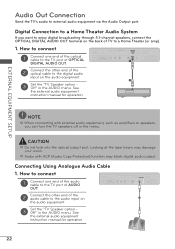
... of AUDIO OUT. 2 Connect the other end of the audio cable to the digital audio input on 1 the audio equipment. 3 Set the "TV Speaker option Off" in the AUDIO menu. EXTERNAL EQUIPMENT SETUP NOTE a When connecting with ACP (Audio Copy Protection) function may damage your vision. ...laser beam may block digital audio output. Connecting Using Analogue Audio Cable 1. How to connect 1 Connect one end of the optical cable to the TV port of OPTICAL 1 DIGITAL AUDIO OUT. 2 Connect the other end of the optical cable to the audio input on the audio equipment. 2 3 Set...
... of AUDIO OUT. 2 Connect the other end of the audio cable to the digital audio input on 1 the audio equipment. 3 Set the "TV Speaker option Off" in the AUDIO menu. EXTERNAL EQUIPMENT SETUP NOTE a When connecting with ACP (Audio Copy Protection) function may damage your vision. ...laser beam may block digital audio output. Connecting Using Analogue Audio Cable 1. How to connect 1 Connect one end of the optical cable to the TV port of OPTICAL 1 DIGITAL AUDIO OUT. 2 Connect the other end of the optical cable to the audio input on the audio equipment. 2 3 Set...


