
Owner's Manual
Page 2
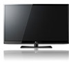
OWNER'S MANUAL PLASMA TV Please read this manual carefully before operating your set and retain it for future reference. 42PJ250 50PJ250 50PK250 60PK250 60PK280 60PK290 42PJ340 50PJ340 42PJ350 50PJ350 50PK350 50PK340 50PK540 60PK540 P/NO : SAC34173302 (1004-REV02) 42PJ550 50PJ550 50PK550 60PK550 42PJ350C 50PJ350C 50PK550C 60PK550C www.lg.com
OWNER'S MANUAL PLASMA TV Please read this manual carefully before operating your set and retain it for future reference. 42PJ250 50PJ250 50PK250 60PK250 60PK280 60PK290 42PJ340 50PJ340 42PJ350 50PJ350 50PK350 50PK340 50PK540 60PK540 P/NO : SAC34173302 (1004-REV02) 42PJ550 50PJ550 50PK550 60PK550 42PJ350C 50PJ350C 50PK550C 60PK550C www.lg.com
Owner's Manual
Page 3
.../ CAUTION TO REDUCE THE RISK OF ELECTRIC SHOCK DO NOT REMOVE COVER (OR BACK). REFER TO QUALIFIED SERVICE PERSONNEL. NOTE TO CABLE/TV INSTALLER This reminder is intended to alert the user to the following measures: - These limits are designed to radio communications. The lightning ...flash with the instructions, may be determined by turning the equipment off and on a circuit different from LG Electronics. WARNING/CAUTION TO REDUCE THE RISK OF FIRE AND ELECTRIC SHOCK, DO NOT EXPOSE THIS PRODUCT TO RAIN OR MOISTURE. ...
.../ CAUTION TO REDUCE THE RISK OF ELECTRIC SHOCK DO NOT REMOVE COVER (OR BACK). REFER TO QUALIFIED SERVICE PERSONNEL. NOTE TO CABLE/TV INSTALLER This reminder is intended to alert the user to the following measures: - These limits are designed to radio communications. The lightning ...flash with the instructions, may be determined by turning the equipment off and on a circuit different from LG Electronics. WARNING/CAUTION TO REDUCE THE RISK OF FIRE AND ELECTRIC SHOCK, DO NOT EXPOSE THIS PRODUCT TO RAIN OR MOISTURE. ...
Owner's Manual
Page 5
... must remain readily operable. 19 "As long as this could result in a door, or walked upon a dedicated circuit; on the power cord to be certain. a TV with liquids, such as being twisted, kinked, pinched, closed in electric shock or fire. Protect the power cord from the AC power source even if... additional outlets or branch circuits. If grounding methods are dangerous. The plug must be placed upon . Do not make sure 12 not to install the TV by connecting it , discontinue use a damaged or loose power cord. Be sure do not drop onto the screen with wet hands. Do not touch ...
... must remain readily operable. 19 "As long as this could result in a door, or walked upon a dedicated circuit; on the power cord to be certain. a TV with liquids, such as being twisted, kinked, pinched, closed in electric shock or fire. Protect the power cord from the AC power source even if... additional outlets or branch circuits. If grounding methods are dangerous. The plug must be placed upon . Do not make sure 12 not to install the TV by connecting it , discontinue use a damaged or loose power cord. Be sure do not drop onto the screen with wet hands. Do not touch ...
Owner's Manual
Page 6
... with hand or sharp object such as nail, pencil or pen, or make a scratch on the TV as electric shock may occur. Do not install in . Do not allow a impact shock onto the panel... against or put stress on the front panel of the lead-in the U.S.A. When watching the TV for the grounding electrode. NEC: National Electrical Code 21 Cleaning When cleaning, unplug the power cord and... scrub gently with respect to carry larger TVs. Section 810 of the National Electrical Code (NEC) in wire to an antenna discharge unit, size...
... with hand or sharp object such as nail, pencil or pen, or make a scratch on the TV as electric shock may occur. Do not install in . Do not allow a impact shock onto the panel... against or put stress on the front panel of the lead-in the U.S.A. When watching the TV for the grounding electrode. NEC: National Electrical Code 21 Cleaning When cleaning, unplug the power cord and... scrub gently with respect to carry larger TVs. Section 810 of the National Electrical Code (NEC) in wire to an antenna discharge unit, size...
Owner's Manual
Page 7
...13 Stand Instruction 15 Cable Management 17 Desktop Pedestal Installation 18 Swivel Stand 18 VESA Wall Mounting 19 Securing the TV to the wall to prevent falling when the TV is used on a stand 20 Antenna or Cable Connection 21 EXTERNAL EQUIPMENT SETUP HD Receiver Setup 22 DVD Setup... 25 VCR Setup 27 Other A/V Source Setup 28 USB Connection 28 Audio Out Connection 29 PC Setup 30 WATCHING TV / CHANNEL CONTROL Remote Control Functions 36 Turning On TV 38 Channel Selection 38 Volume Adjustment 38 Initial Setting 39 On-Screen Menus Selection 40 Quick Menu 42 Channel Setup ...
...13 Stand Instruction 15 Cable Management 17 Desktop Pedestal Installation 18 Swivel Stand 18 VESA Wall Mounting 19 Securing the TV to the wall to prevent falling when the TV is used on a stand 20 Antenna or Cable Connection 21 EXTERNAL EQUIPMENT SETUP HD Receiver Setup 22 DVD Setup... 25 VCR Setup 27 Other A/V Source Setup 28 USB Connection 28 Audio Out Connection 29 PC Setup 30 WATCHING TV / CHANNEL CONTROL Remote Control Functions 36 Turning On TV 38 Channel Selection 38 Volume Adjustment 38 Initial Setting 39 On-Screen Menus Selection 40 Quick Menu 42 Channel Setup ...
Owner's Manual
Page 8
...On/Off Time Setting 92 Sleep Timer Setting 93 PARENTAL CONTROL / RATINGS Set Password & Lock System 94 Channel Blocking 97 Movie & TV Rating 98 Downloadable Rating 103 External Input Blocking 104 Key lock 105 APPENDIX Troubleshooting 106 Maintenance 108 Product Specifications 109 IR Codes 112 ...Preset Sound Settings (Sound Mode 78 Sound Setting Adjustment - Caption Option 89 TIME SETTING Clock Setting - User Mode 79 Balance 81 TV Speakers On/Off Setup 82 Audio Reset 83 Stereo/SAP Broadcasts Setup 84 Audio Language 85 On-Screen Menus Language Selection 86 Caption Mode...
...On/Off Time Setting 92 Sleep Timer Setting 93 PARENTAL CONTROL / RATINGS Set Password & Lock System 94 Channel Blocking 97 Movie & TV Rating 98 Downloadable Rating 103 External Input Blocking 104 Key lock 105 APPENDIX Troubleshooting 106 Maintenance 108 Product Specifications 109 IR Codes 112 ...Preset Sound Settings (Sound Mode 78 Sound Setting Adjustment - Caption Option 89 TIME SETTING Clock Setting - User Mode 79 Balance 81 TV Speakers On/Off Setup 82 Audio Reset 83 Stereo/SAP Broadcasts Setup 84 Audio Language 85 On-Screen Menus Language Selection 86 Caption Mode...

Owner's Manual
Page 9
... pleasing to watch and which can also occur on the letterboxed areas of your TV through the ISFccc mode. View videos and photos and listen to evaluate its surroundings. I Image burn can only sense brightness of ambient light, LG's "Intelligent Sensor" uses 4,096 sensing steps to music on model). It allows the...
... pleasing to watch and which can also occur on the letterboxed areas of your TV through the ISFccc mode. View videos and photos and listen to evaluate its surroundings. I Image burn can only sense brightness of ambient light, LG's "Intelligent Sensor" uses 4,096 sensing steps to music on model). It allows the...

Owner's Manual
Page 10
... with the polishing cloth. close to P.15) x 2 Cable Holder * Wipe spots on the ferrite core twice, and Ferrite Core then plug the cables into the TV as shown in the PC Audio cable. Ferrite Core tromagnetic waves that the following accessories are included with ferrite cores to AUDIO IN(RGB/DVI... Extras D-sub 15 pin Cable When using the VGA (D-sub 15 pin cable) PC connection, the user must use shielded signal interface cables with your TV. models.) AUDIO IN (RGB/DVI) Ferrite core can be used to AUDIO IN(RGB/DVI) jack available for all models.) Place the ferrite core ...
... with the polishing cloth. close to P.15) x 2 Cable Holder * Wipe spots on the ferrite core twice, and Ferrite Core then plug the cables into the TV as shown in the PC Audio cable. Ferrite Core tromagnetic waves that the following accessories are included with ferrite cores to AUDIO IN(RGB/DVI... Extras D-sub 15 pin Cable When using the VGA (D-sub 15 pin cable) PC connection, the user must use shielded signal interface cables with your TV. models.) AUDIO IN (RGB/DVI) Ferrite core can be used to AUDIO IN(RGB/DVI) jack available for all models.) Place the ferrite core ...
Owner's Manual
Page 11
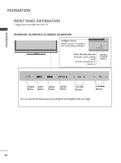
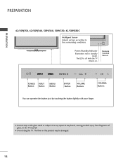
The LED is off while the TV remains on. ENTER VOL CH Power/Standby Indicator Illuminates red in standby mode. PREPARATION PREPARATION FRONT PANEL INFORMATION I Image shown may differ from your finger. 10 Remote Control Sensor ENTER VOL CH POWER INPUT Button Button MENU Button ENTER Button VOLUME Buttons CHANNEL Buttons ENTER You can operate the button just by touching the button lightly with your TV. 50/60PK550, 50/60PK540, 42/50PJ550, 50/60PK550C Intelligent Sensor Adjusts picture according to the surrounding conditions.
The LED is off while the TV remains on. ENTER VOL CH Power/Standby Indicator Illuminates red in standby mode. PREPARATION PREPARATION FRONT PANEL INFORMATION I Image shown may differ from your finger. 10 Remote Control Sensor ENTER VOL CH POWER INPUT Button Button MENU Button ENTER Button VOLUME Buttons CHANNEL Buttons ENTER You can operate the button just by touching the button lightly with your TV. 50/60PK550, 50/60PK540, 42/50PJ550, 50/60PK550C Intelligent Sensor Adjusts picture according to the surrounding conditions.
Owner's Manual
Page 12
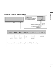
ENTER VOL CH Power/Standby Indicator Illuminates red in standby mode. The LED is off while the TV remains on. Remote Control Sensor ENTER VOL CH POWER INPUT Button Button MENU Button ENTER Button VOLUME Buttons CHANNEL Buttons ENTER You can operate the button just by touching the button lightly with your finger. 11 PREPARATION 50/60PK250, 42/50PJ250, 60PK280, 60PK290 Intelligent Sensor Adjusts picture according to the surrounding conditions.
ENTER VOL CH Power/Standby Indicator Illuminates red in standby mode. The LED is off while the TV remains on. Remote Control Sensor ENTER VOL CH POWER INPUT Button Button MENU Button ENTER Button VOLUME Buttons CHANNEL Buttons ENTER You can operate the button just by touching the button lightly with your finger. 11 PREPARATION 50/60PK250, 42/50PJ250, 60PK280, 60PK290 Intelligent Sensor Adjusts picture according to the surrounding conditions.
Owner's Manual
Page 13
The LED is off while the TV remains on the glass stand or subject it to the surrounding conditions. Remote Control Sensor ENTER VOL CH VOL POWER Button INPUT Button CH MENU ... your finger. The floor or the product may fall. ENTER VOL CH Power/Standby Indicator Illuminates red in standby mode. G Do not drag the TV. PREPARATION PREPARATION 42/50PJ350, 42/50PJ340, 50PK340, 50PK350, 42/50PJ350C Intelligent Sensor Adjusts picture according to any impact.It may break, causing possible injury from fragments of...
The LED is off while the TV remains on the glass stand or subject it to the surrounding conditions. Remote Control Sensor ENTER VOL CH VOL POWER Button INPUT Button CH MENU ... your finger. The floor or the product may fall. ENTER VOL CH Power/Standby Indicator Illuminates red in standby mode. G Do not drag the TV. PREPARATION PREPARATION 42/50PJ350, 42/50PJ340, 50PK340, 50PK350, 42/50PJ350C Intelligent Sensor Adjusts picture according to any impact.It may break, causing possible injury from fragments of...
Owner's Manual
Page 14
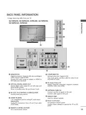
R VIDEO L/MONO AUDIO R HDMI IN 3 SERVICE ONLY R R PREPARATION BACK PANEL INFORMATION I Image shown may differ from your TV. 42/50PJ250, 50/60PK250, 60PK280, 42/50PJ340, 50/60PK540, 50PK340 9 1 7 10 AV IN 2 2 4 5 7 OPTICAL DIGITAL AUDIO OUT AUDIO IN (RGB/DVI) REMOTE CONTROL IN...Supports HD video and Digital audio. Supports HD. Supports standard definition video only (480i). 8 ANTENNA/CABLE IN Connect over-the air signals to operate the TV on DC power. 13 Connect cable signals to DVI cable (not included) 2 OPTICAL DIGITAL AUDIO OUT Optical digital audio output for use with amps and...
R VIDEO L/MONO AUDIO R HDMI IN 3 SERVICE ONLY R R PREPARATION BACK PANEL INFORMATION I Image shown may differ from your TV. 42/50PJ250, 50/60PK250, 60PK280, 42/50PJ340, 50/60PK540, 50PK340 9 1 7 10 AV IN 2 2 4 5 7 OPTICAL DIGITAL AUDIO OUT AUDIO IN (RGB/DVI) REMOTE CONTROL IN...Supports HD video and Digital audio. Supports HD. Supports standard definition video only (480i). 8 ANTENNA/CABLE IN Connect over-the air signals to operate the TV on DC power. 13 Connect cable signals to DVI cable (not included) 2 OPTICAL DIGITAL AUDIO OUT Optical digital audio output for use with amps and...
Owner's Manual
Page 15
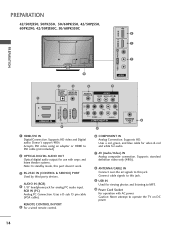
... OUT Optical digital audio output for viewing photos and listening to this jack. Accepts DVI video using an adapter or HDMI to operate the TV on DC power. 14 AUDIO IN (RGB) 4 1/8" headphone jack for audio. 7 AV (Audio/Video) IN Analog composite connection. RGB... IN (PC) Analog PC Connection. Doesn't support 480i. R VIDEO L/MONO AUDIO R HDMI IN 3 USB IN R R PREPARATION 42/50PJ350, 50PK350, 50/60PK550, 42/50PJ550, 60PK290, 42/50PJ350C, 50/60PK550C 9 1 PREPARATION 7 10 AV IN 2 2 4 5 7 OPTICAL DIGITAL AUDIO OUT AUDIO IN (RGB...
... OUT Optical digital audio output for viewing photos and listening to this jack. Accepts DVI video using an adapter or HDMI to operate the TV on DC power. 14 AUDIO IN (RGB) 4 1/8" headphone jack for audio. 7 AV (Audio/Video) IN Analog composite connection. RGB... IN (PC) Analog PC Connection. Doesn't support 480i. R VIDEO L/MONO AUDIO R HDMI IN 3 USB IN R R PREPARATION 42/50PJ350, 50PK350, 50/60PK550, 42/50PJ550, 60PK290, 42/50PJ350C, 50/60PK550C 9 1 PREPARATION 7 10 AV IN 2 2 4 5 7 OPTICAL DIGITAL AUDIO OUT AUDIO IN (RGB...
Owner's Manual
Page 16
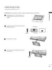
Installation (Except 60PK250, 60PK540, 60PK550, 60PK280, 60PK290, 60PK550C) 1 Carefully place the TV screen side down on a cushioned surface to protect the screen from your TV. x 3 M5x14 Stand Body Stand Base 3 Assemble the TV as shown. 4 Fix the 4 bolts securely using the holes in the back of the TV. x 4 M4x28 15 PREPARATION STAND INSTRUCTION I Image shown may differ from damage. 2 Assemble the parts of the Stand Body with the Stand Base of the TV.
Installation (Except 60PK250, 60PK540, 60PK550, 60PK280, 60PK290, 60PK550C) 1 Carefully place the TV screen side down on a cushioned surface to protect the screen from your TV. x 3 M5x14 Stand Body Stand Base 3 Assemble the TV as shown. 4 Fix the 4 bolts securely using the holes in the back of the TV. x 4 M4x28 15 PREPARATION STAND INSTRUCTION I Image shown may differ from damage. 2 Assemble the parts of the Stand Body with the Stand Base of the TV.
Owner's Manual
Page 17
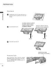
... protection cover over the hole for the stand. PREPARATION PREPARATION Detachment 1 Carefully place the TV screen side down on a cushioned surface to the Outsides.) Press the PROTECTION COVER into the TV until you hear it click. 16 PROTECTION COVER (Fix a Guide to protect the screen... from damage. 2 Loose the bolts from TV. (42/50PJ250, 50PK250, 42/50PJ340, 42/50PJ350, 50PK350, 50PK340, 50PK540, 42/50PJ550, 50PK550, 42/50PJ350C,...
... protection cover over the hole for the stand. PREPARATION PREPARATION Detachment 1 Carefully place the TV screen side down on a cushioned surface to the Outsides.) Press the PROTECTION COVER into the TV until you hear it click. 16 PROTECTION COVER (Fix a Guide to protect the screen... from damage. 2 Loose the bolts from TV. (42/50PJ250, 50PK250, 42/50PJ340, 42/50PJ350, 50PK350, 50PK340, 50PK540, 42/50PJ550, 50PK550, 42/50PJ350C,...

Owner's Manual
Page 18
PREPARATION CABLE MANAGEMENT I Image shown may differ from your TV. 1 After connecting the cables as necessary, install CABLE HOLDER as shown and bundle the cables. To connect additional equipment, see EXTERNAL EQUIPMENT SETUP section. CABLE HOLDER 17
PREPARATION CABLE MANAGEMENT I Image shown may differ from your TV. 1 After connecting the cables as necessary, install CABLE HOLDER as shown and bundle the cables. To connect additional equipment, see EXTERNAL EQUIPMENT SETUP section. CABLE HOLDER 17

Owner's Manual
Page 19
G Do not mount near or above any type of 4 inches on all models.) After installing the TV, you can adjust the TV manually to the left or right direction by following the clearance recommendations. SWIVEL STAND (This feature is not available for all four sides from your viewing position. 18 PREPARATION PREPARATION DESKTOP PEDESTAL INSTALLATION I Image shown may differ from the wall. 4 inches 4 inches 4 inches 4 inches CAUTION G Ensure adequate ventilation by 20 degrees to suit your TV. For proper ventilation, allow a clearance of heat source.
G Do not mount near or above any type of 4 inches on all models.) After installing the TV, you can adjust the TV manually to the left or right direction by following the clearance recommendations. SWIVEL STAND (This feature is not available for all four sides from your viewing position. 18 PREPARATION PREPARATION DESKTOP PEDESTAL INSTALLATION I Image shown may differ from the wall. 4 inches 4 inches 4 inches 4 inches CAUTION G Ensure adequate ventilation by 20 degrees to suit your TV. For proper ventilation, allow a clearance of heat source.
Owner's Manual
Page 20
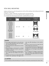
...longer then the standard dimension, as they may damage the TV or cause the TV to a fall and result in severe personal injury. G Do not use an LG brand wall mount when mounting the TV to the floor. LG is used . CAUTION G Do not install your wall ... mount on a solid wall perpendicular to a wall. Model VESA (A * B) A Standard Screw Quantity B Wall Mounting bracket (sold separately) 50PK550, 42/50PJ340 42/50PJ350, 42/50PJ250 50PK250, 50PK340, 400 * 400 M6 50PK350, 50PK540, 42/50PJ550, 42/50PJ350C, 50PK550C 60PK550, 60PK250, 60PK280, 60PK290, 50PK540, 60PK550C 600 * 400...
...longer then the standard dimension, as they may damage the TV or cause the TV to a fall and result in severe personal injury. G Do not use an LG brand wall mount when mounting the TV to the floor. LG is used . CAUTION G Do not install your wall ... mount on a solid wall perpendicular to a wall. Model VESA (A * B) A Standard Screw Quantity B Wall Mounting bracket (sold separately) 50PK550, 42/50PJ340 42/50PJ350, 42/50PJ250 50PK250, 50PK340, 400 * 400 M6 50PK350, 50PK540, 42/50PJ550, 42/50PJ350C, 50PK550C 60PK550, 60PK250, 60PK280, 60PK290, 50PK540, 60PK550C 600 * 400...
Owner's Manual
Page 21
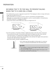
... your product has the bolts in the eye-bolts position before inserting the eye-bolts, loosen the bolts. * Insert the eye-bolts or TV brackets/bolts and tighten them securely in a forward direction, potentially causing injury or damaging the product. It is mounted on the wall to the ... horizontal between the wall and the product. ! I Image shown may differ from tipping over if pushed backwards. Match the height of the TV. I Insert the eye-bolts (or TV brackets and bolts) to tighten the product to support the size and weight of the bracket that children don't climb on the...
... your product has the bolts in the eye-bolts position before inserting the eye-bolts, loosen the bolts. * Insert the eye-bolts or TV brackets/bolts and tighten them securely in a forward direction, potentially causing injury or damaging the product. It is mounted on the wall to the ... horizontal between the wall and the product. ! I Image shown may differ from tipping over if pushed backwards. Match the height of the TV. I Insert the eye-bolts (or TV brackets and bolts) to tighten the product to support the size and weight of the bracket that children don't climb on the...
Owner's Manual
Page 22
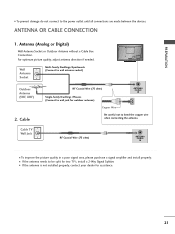
... are made between the devices. Wall Antenna Socket Multi-family Dwellings/Apartments (Connect to bend the copper wire when connecting the antenna. Cable Cable TV Wall Jack RF Coaxial Wire (75 ohm) Single-family Dwellings /Houses (Connect to wall jack for outdoor antenna) ANTENNA /CABLE IN Copper Wire...not to wall antenna socket) Outdoor Antenna (VHF, UHF) 2. PREPARATION () VARIABLE AUDIO OUT R I If the antenna needs to be split for two TV's, install a 2-Way Signal Splitter. ANTENNA OR CABLE CONNECTION R 1. For optimum picture quality, adjust antenna direction if needed.
... are made between the devices. Wall Antenna Socket Multi-family Dwellings/Apartments (Connect to bend the copper wire when connecting the antenna. Cable Cable TV Wall Jack RF Coaxial Wire (75 ohm) Single-family Dwellings /Houses (Connect to wall jack for outdoor antenna) ANTENNA /CABLE IN Copper Wire...not to wall antenna socket) Outdoor Antenna (VHF, UHF) 2. PREPARATION () VARIABLE AUDIO OUT R I If the antenna needs to be split for two TV's, install a 2-Way Signal Splitter. ANTENNA OR CABLE CONNECTION R 1. For optimum picture quality, adjust antenna direction if needed.


