Owner's Manual
Page 7
...Input List 49 Input Label 50 AV Mode 51 SIMPLINK 52 USB Entry Modes 54 Photo List 55 Music List 61 PICTURE CONTROL Picture Size (Aspect Ratio) Control 64 Picture Wizard 66 Energy Saving 68 Preset Picture Settings(Picture Mode 69 Manual Picture Adjustment - Auto Scan (Auto Tuning ...Setup 25 VCR Setup 27 Other A/V Source Setup 28 USB Connection 28 Audio Out Connection 29 PC Setup 30 WATCHING TV / CHANNEL CONTROL Remote Control Functions 36 Turning On TV 38 Channel Selection 38 Volume Adjustment 38 Initial Setting 39 On-Screen Menus Selection 40 Quick Menu 42 Channel ...
...Input List 49 Input Label 50 AV Mode 51 SIMPLINK 52 USB Entry Modes 54 Photo List 55 Music List 61 PICTURE CONTROL Picture Size (Aspect Ratio) Control 64 Picture Wizard 66 Energy Saving 68 Preset Picture Settings(Picture Mode 69 Manual Picture Adjustment - Auto Scan (Auto Tuning ...Setup 25 VCR Setup 27 Other A/V Source Setup 28 USB Connection 28 Audio Out Connection 29 PC Setup 30 WATCHING TV / CHANNEL CONTROL Remote Control Functions 36 Turning On TV 38 Channel Selection 38 Volume Adjustment 38 Initial Setting 39 On-Screen Menus Selection 40 Quick Menu 42 Channel ...

Owner's Manual
Page 10
... EXIT FREEZE Q.MENU or 753 86 LIST 0 9 MENU VOL FAVMARK MUTERATIO CH FLASHBK INFO P A G E ENTER Q.MENU BACK 1.5V 1.5V EXIT FREEZE Owner's Manual CD Manual Remote Control, Batteries (Except 60PK250, 60PK540, 60PK550, 60PK280, 60PK290, 60PK550C) Power Cord Protection Cover (Refer to P.16) x 4 x 3 M4x28 M5x14 Bolts for all models.) Place the ferrite core...
... EXIT FREEZE Q.MENU or 753 86 LIST 0 9 MENU VOL FAVMARK MUTERATIO CH FLASHBK INFO P A G E ENTER Q.MENU BACK 1.5V 1.5V EXIT FREEZE Owner's Manual CD Manual Remote Control, Batteries (Except 60PK250, 60PK540, 60PK550, 60PK280, 60PK290, 60PK550C) Power Cord Protection Cover (Refer to P.16) x 4 x 3 M4x28 M5x14 Bolts for all models.) Place the ferrite core...
Owner's Manual
Page 11
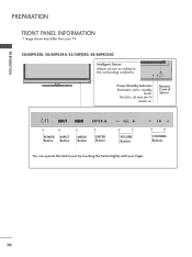
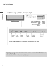
The LED is off while the TV remains on. PREPARATION PREPARATION FRONT PANEL INFORMATION I Image shown may differ from your finger. 10 Remote Control Sensor ENTER VOL CH POWER INPUT Button Button MENU Button ENTER Button VOLUME Buttons CHANNEL Buttons ENTER You can operate the button just by touching the button lightly with your TV. 50/60PK550, 50/60PK540, 42/50PJ550, 50/60PK550C Intelligent Sensor Adjusts picture according to the surrounding conditions. ENTER VOL CH Power/Standby Indicator Illuminates red in standby mode.
The LED is off while the TV remains on. PREPARATION PREPARATION FRONT PANEL INFORMATION I Image shown may differ from your finger. 10 Remote Control Sensor ENTER VOL CH POWER INPUT Button Button MENU Button ENTER Button VOLUME Buttons CHANNEL Buttons ENTER You can operate the button just by touching the button lightly with your TV. 50/60PK550, 50/60PK540, 42/50PJ550, 50/60PK550C Intelligent Sensor Adjusts picture according to the surrounding conditions. ENTER VOL CH Power/Standby Indicator Illuminates red in standby mode.
Owner's Manual
Page 12
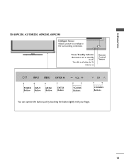
PREPARATION 50/60PK250, 42/50PJ250, 60PK280, 60PK290 Intelligent Sensor Adjusts picture according to the surrounding conditions. ENTER VOL CH Power/Standby Indicator Illuminates red in standby mode. The LED is off while the TV remains on. Remote Control Sensor ENTER VOL CH POWER INPUT Button Button MENU Button ENTER Button VOLUME Buttons CHANNEL Buttons ENTER You can operate the button just by touching the button lightly with your finger. 11
PREPARATION 50/60PK250, 42/50PJ250, 60PK280, 60PK290 Intelligent Sensor Adjusts picture according to the surrounding conditions. ENTER VOL CH Power/Standby Indicator Illuminates red in standby mode. The LED is off while the TV remains on. Remote Control Sensor ENTER VOL CH POWER INPUT Button Button MENU Button ENTER Button VOLUME Buttons CHANNEL Buttons ENTER You can operate the button just by touching the button lightly with your finger. 11
Owner's Manual
Page 13
... off while the TV remains on the glass stand or subject it to the surrounding conditions. G Do not drag the TV. Remote Control Sensor ENTER VOL CH VOL POWER Button INPUT Button CH MENU Button ENTER Button VOLUME Buttons CHANNEL Buttons You can operate the button ...or the product may fall. ENTER VOL CH Power/Standby Indicator Illuminates red in standby mode. G Do not step on . PREPARATION PREPARATION 42/50PJ350, 42/50PJ340, 50PK340, 50PK350, 42/50PJ350C Intelligent Sensor Adjusts picture according to any impact.It may break, causing possible injury from fragments of ...
... off while the TV remains on the glass stand or subject it to the surrounding conditions. G Do not drag the TV. Remote Control Sensor ENTER VOL CH VOL POWER Button INPUT Button CH MENU Button ENTER Button VOLUME Buttons CHANNEL Buttons You can operate the button ...or the product may fall. ENTER VOL CH Power/Standby Indicator Illuminates red in standby mode. G Do not step on . PREPARATION PREPARATION 42/50PJ350, 42/50PJ340, 50PK340, 50PK350, 42/50PJ350C Intelligent Sensor Adjusts picture according to any impact.It may break, causing possible injury from fragments of ...
Owner's Manual
Page 14
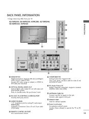
... 60PK280, 42/50PJ340, 50/60PK540, 50PK340 9 1 7 10 AV IN 2 2 4 5 7 OPTICAL DIGITAL AUDIO OUT AUDIO IN (RGB/DVI) REMOTE CONTROL IN AV IN 1 VIDEO /MONO AUDIO 1 () VARIABLE AUDIO OUT 2 1 HDMI/DVI IN 3 RS-232C IN (CONTROL & SERVICE) RGB IN (PC) 2 L R 1 VIDEO AUDIO COMPONENT IN 6 ANTENNA /CABLE 8 IN 1 HDMI/DVI IN Digital Connection. Doesn... and blue cable for video & red and white for audio. 7 AV (Audio/Video) IN Analog composite connection. Uses a D-sub 15 pin cable (VGA cable). 5 REMOTE CONTROL IN PORT For a wired remote control. 6 COMPONENT IN Analog Connection.
... 60PK280, 42/50PJ340, 50/60PK540, 50PK340 9 1 7 10 AV IN 2 2 4 5 7 OPTICAL DIGITAL AUDIO OUT AUDIO IN (RGB/DVI) REMOTE CONTROL IN AV IN 1 VIDEO /MONO AUDIO 1 () VARIABLE AUDIO OUT 2 1 HDMI/DVI IN 3 RS-232C IN (CONTROL & SERVICE) RGB IN (PC) 2 L R 1 VIDEO AUDIO COMPONENT IN 6 ANTENNA /CABLE 8 IN 1 HDMI/DVI IN Digital Connection. Doesn... and blue cable for video & red and white for audio. 7 AV (Audio/Video) IN Analog composite connection. Uses a D-sub 15 pin cable (VGA cable). 5 REMOTE CONTROL IN PORT For a wired remote control. 6 COMPONENT IN Analog Connection.
Owner's Manual
Page 15
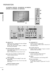
... 15 pin cable (VGA cable). R VIDEO L/MONO AUDIO R HDMI IN 3 USB IN R R PREPARATION 42/50PJ350, 50PK350, 50/60PK550, 42/50PJ550, 60PK290, 42/50PJ350C, 50/60PK550C 9 1 PREPARATION 7 10 AV IN 2 2 4 5 7 OPTICAL DIGITAL AUDIO OUT AUDIO IN (RGB/DVI) REMOTE CONTROL IN AV IN 1 VIDEO /MONO AUDIO 1 () VARIABLE AUDIO OUT 2 1 HDMI/DVI IN 3 RS-232C...
... 15 pin cable (VGA cable). R VIDEO L/MONO AUDIO R HDMI IN 3 USB IN R R PREPARATION 42/50PJ350, 50PK350, 50/60PK550, 42/50PJ550, 60PK290, 42/50PJ350C, 50/60PK550C 9 1 PREPARATION 7 10 AV IN 2 2 4 5 7 OPTICAL DIGITAL AUDIO OUT AUDIO IN (RGB/DVI) REMOTE CONTROL IN AV IN 1 VIDEO /MONO AUDIO 1 () VARIABLE AUDIO OUT 2 1 HDMI/DVI IN 3 RS-232C...
Owner's Manual
Page 23
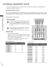
...TV. HD RECEIVER SETUP This TV can receive Digital Over-the-air/Cable signals without an external digital set -top box. I Turn on the remote control. EXTERNAL EQUIPMENT SETUP I To prevent the equipment damage, never plug in any power cords until you do receive digital signals from your TV. I...the TV using the INPUT button on the digital set -top box to the COMPONENT IN VIDEO 1 jacks on the TV. 1 2 O IN /DVI) REMOTE CONTROL IN AV IN 1 VIDEO /MONO AUDIO 2 L R 1 VIDEO AUDIO COMPONENT IN ANT CA Supported Resolutions Signal 480i 480p 720p 1080i 1080p Component Yes Yes ...
...TV. HD RECEIVER SETUP This TV can receive Digital Over-the-air/Cable signals without an external digital set -top box. I Turn on the remote control. EXTERNAL EQUIPMENT SETUP I To prevent the equipment damage, never plug in any power cords until you do receive digital signals from your TV. I...the TV using the INPUT button on the digital set -top box to the COMPONENT IN VIDEO 1 jacks on the TV. 1 2 O IN /DVI) REMOTE CONTROL IN AV IN 1 VIDEO /MONO AUDIO 2 L R 1 VIDEO AUDIO COMPONENT IN ANT CA Supported Resolutions Signal 480i 480p 720p 1080i 1080p Component Yes Yes ...
Owner's Manual
Page 24
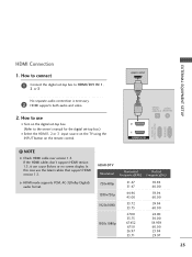
... connection is necessary. 2 HDMI supports both audio and video. 2. HDMI-DTV OUTPUT 1 OPTICAL DIGITAL AUDIO OUT AUDIO (RGB/DVI) 2 1 HDMI/DVI IN RS-232C IN (CONTROL & SERVICE) RGB IN(PC) ! NOTE G Check HDMI cable over version 1.3. In this case use I Turn on the digital set-top box. (Refer to the owner... -top box to connect 1 Connect the digital set -top box.) I Select the HDMI1, 2 or 3 input source on the TV using the INPUT button on the remote control.
... connection is necessary. 2 HDMI supports both audio and video. 2. HDMI-DTV OUTPUT 1 OPTICAL DIGITAL AUDIO OUT AUDIO (RGB/DVI) 2 1 HDMI/DVI IN RS-232C IN (CONTROL & SERVICE) RGB IN(PC) ! NOTE G Check HDMI cable over version 1.3. In this case use I Turn on the digital set-top box. (Refer to the owner... -top box to connect 1 Connect the digital set -top box.) I Select the HDMI1, 2 or 3 input source on the TV using the INPUT button on the remote control.
Owner's Manual
Page 25
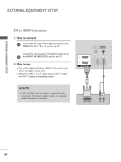
... box.) I Turn on the TV. 2. How to HDMI cable or adapter is necessary. OPTICAL DIGITAL AUDIO OUT AUDIO IN (RGB/DVI) R CO RS-232C IN (CONTROL & SERVICE) RGB IN (PC) 2 2 1 1 HDMI/DVI IN 1 2 DVI-DTV OUTPUT R L 24 EXTERNAL EQUIPMENT SETUP EXTERNAL EQUIPMENT SETUP DVI to the owner's manual for this connection...
... box.) I Turn on the TV. 2. How to HDMI cable or adapter is necessary. OPTICAL DIGITAL AUDIO OUT AUDIO IN (RGB/DVI) R CO RS-232C IN (CONTROL & SERVICE) RGB IN (PC) 2 2 1 1 HDMI/DVI IN 1 2 DVI-DTV OUTPUT R L 24 EXTERNAL EQUIPMENT SETUP EXTERNAL EQUIPMENT SETUP DVI to the owner's manual for this connection...
Owner's Manual
Page 26
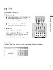
... COMPONENT IN AUDIO 1 jacks on the DVD player, insert a DVD. I Refer to the DVD player's manual for operating instructions. 1 2 DIO IN B/DVI) REMOTE CONTROL IN AV IN 1 VIDEO /MONO AUDIO 2 L R 1 VIDEO AUDIO A COMPONENT IN Component Input ports To get better picture quality, connect a DVD player to ...use I Turn on the TV. 2. Component ports on the TV Y Y Video output ports Y on the remote control. How to the component input ports as shown below. Match the jack colors (Y = green, PB = blue, and PR = red). I Select the ...
... COMPONENT IN AUDIO 1 jacks on the DVD player, insert a DVD. I Refer to the DVD player's manual for operating instructions. 1 2 DIO IN B/DVI) REMOTE CONTROL IN AV IN 1 VIDEO /MONO AUDIO 2 L R 1 VIDEO AUDIO A COMPONENT IN Component Input ports To get better picture quality, connect a DVD player to ...use I Turn on the TV. 2. Component ports on the TV Y Y Video output ports Y on the remote control. How to the component input ports as shown below. Match the jack colors (Y = green, PB = blue, and PR = red). I Select the ...
Owner's Manual
Page 27
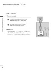
How to connect 1 Connect the HDMI output of the DVD to the DVD player's manual for operating instructions. HDMI-DVD OUTPUT 1 OPTICAL DIGITAL AUDIO OUT AUD (RGB/D 2 1 HDMI/DVI IN RS-232C IN (CONTROL & SERVICE) RGB IN (PC) 26 I Select the HDMI1, 2 or 3 input source on the TV using the INPUT button on the TV. 2 No separate audio connection is necessary. EXTERNAL EQUIPMENT SETUP EXTERNAL EQUIPMENT SETUP HDMI Connection 1. How to use I Refer to the HDMI/DVI IN 1, 2 or 3 jack on the remote control. HDMI supports both audio and video. 2.
How to connect 1 Connect the HDMI output of the DVD to the DVD player's manual for operating instructions. HDMI-DVD OUTPUT 1 OPTICAL DIGITAL AUDIO OUT AUD (RGB/D 2 1 HDMI/DVI IN RS-232C IN (CONTROL & SERVICE) RGB IN (PC) 26 I Select the HDMI1, 2 or 3 input source on the TV using the INPUT button on the TV. 2 No separate audio connection is necessary. EXTERNAL EQUIPMENT SETUP EXTERNAL EQUIPMENT SETUP HDMI Connection 1. How to use I Refer to the HDMI/DVI IN 1, 2 or 3 jack on the remote control. HDMI supports both audio and video. 2.
Owner's Manual
Page 28
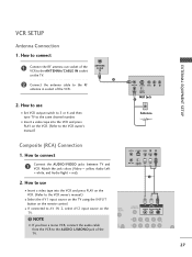
...VIDEO L R ANT IN 2 OUTPUT SWITCH Wall Jack Antenna Composite (RCA) Connection 1. I Insert a video tape into the VCR and press PLAY on the remote control. EXTERNAL EQUIPMENT SETUP VCR SETUP Antenna Connection 1. How to connect 1 Connect the RF antenna out socket of the VCR to the RF antenna in socket... of the TV. (PC) ANT IN S-VIDEO VIDEO L R ANT OUT OUTPUT SWITCH 1 UDIO B/DVI) REMOTE CONTROL IN AV IN 1 VIDEO /MONO AUDIO 2 L R 1 27 ANTENNA/ CABLE IN 1 2 Connect the antenna cable to the ANTENNA/CABLE IN socket on the ...
...VIDEO L R ANT IN 2 OUTPUT SWITCH Wall Jack Antenna Composite (RCA) Connection 1. I Insert a video tape into the VCR and press PLAY on the remote control. EXTERNAL EQUIPMENT SETUP VCR SETUP Antenna Connection 1. How to connect 1 Connect the RF antenna out socket of the VCR to the RF antenna in socket... of the TV. (PC) ANT IN S-VIDEO VIDEO L R ANT OUT OUTPUT SWITCH 1 UDIO B/DVI) REMOTE CONTROL IN AV IN 1 VIDEO /MONO AUDIO 2 L R 1 27 ANTENNA/ CABLE IN 1 2 Connect the antenna cable to the ANTENNA/CABLE IN socket on the ...
Owner's Manual
Page 29
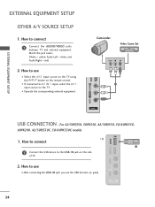
... to the USB I Select the A V 2 input source on the TV using the INPUT button on the remote control. EXTERNAL EQUIPMENT SETUP OTHER A/V SOURCE SETUP 1. How to use the USB function. (G p.54) AV IN 2 28 For 42/50PJ350, 50PK350, 42/50PJ550, 50/60PK550, 60PK290, 42/50PJ350C, 50/60PK550C models 1. I N jack, you use I After connecting...
... to the USB I Select the A V 2 input source on the TV using the INPUT button on the remote control. EXTERNAL EQUIPMENT SETUP OTHER A/V SOURCE SETUP 1. How to use the USB function. (G p.54) AV IN 2 28 For 42/50PJ350, 50PK350, 42/50PJ550, 50/60PK550, 60PK290, 42/50PJ350C, 50/60PK550C models 1. I N jack, you use I After connecting...
Owner's Manual
Page 31
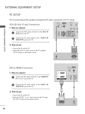
...) RGB IN (PC) 1 2 DVI-PC OUTPUT AUDIO I Select the RGB-PC input source on the TV using the INPUT button on the remote control. How to connect 2 1 Connect the VGA output of the PC to the HDMI/DVI IN 1, 2 or 3 jack on the TV. 2 Connect the PC audio output ... the TV. How to use I Turn on the TV. 2. VGA (D-Sub 15 pin) Connection OPTICAL DIGITAL AUDIO OUT AUDIO IN (RGB/DVI) REMOTE CONTROL IN VIDEO RS-232C IN (CONTROL & SERVICE) RGB IN (PC) 1. RS-232C IN RS-232C IN EXTERNAL EQUIPMENT SETUP EXTERNAL EQUIPMENT SETUP PC SETUP This TV provides Plug and...
...) RGB IN (PC) 1 2 DVI-PC OUTPUT AUDIO I Select the RGB-PC input source on the TV using the INPUT button on the remote control. How to connect 2 1 Connect the VGA output of the PC to the HDMI/DVI IN 1, 2 or 3 jack on the TV. 2 Connect the PC audio output ... the TV. How to use I Turn on the TV. 2. VGA (D-Sub 15 pin) Connection OPTICAL DIGITAL AUDIO OUT AUDIO IN (RGB/DVI) REMOTE CONTROL IN VIDEO RS-232C IN (CONTROL & SERVICE) RGB IN (PC) 1. RS-232C IN RS-232C IN EXTERNAL EQUIPMENT SETUP EXTERNAL EQUIPMENT SETUP PC SETUP This TV provides Plug and...
Owner's Manual
Page 37
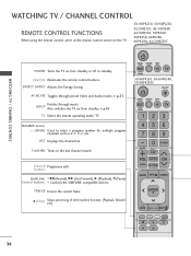
... Video and Audio modes. Colored Programme edit. LIST Displays the channel list. WATCHING TV / CHANNEL CONTROL WATCHING TV / CHANNEL CONTROL REMOTE CONTROL FUNCTIONS When using the remote control, aim it at the remote control sensor on the TV. 50/60PK250, 50/60PJ250, 42/50PJ350, 42/50PJ340, 42/50PJ550, 50PK340, 50PK350, 60PK280, 60PK290, 42/50PJ350C POWER Turns the TV on...
... Video and Audio modes. Colored Programme edit. LIST Displays the channel list. WATCHING TV / CHANNEL CONTROL WATCHING TV / CHANNEL CONTROL REMOTE CONTROL FUNCTIONS When using the remote control, aim it at the remote control sensor on the TV. 50/60PK250, 50/60PJ250, 42/50PJ350, 42/50PJ340, 42/50PJ550, 50PK340, 50PK350, 60PK280, 60PK290, 42/50PJ350C POWER Turns the TV on...

Owner's Manual
Page 39
...mode to turn TV on, press the , INPUT, CH ( or ) button on the TV or press the POWER, INPUT, CH( or ), Number (0~9) button on the remote control. 2 Select the viewing source by pressing the MUTE or VOL (+ or -) button. 38 CHANNEL SELECTION 1 Press the CH ( or ) or NUMBER buttons to standby mode.... 2 If you intend to switch the sound off, press the MUTE button. 3 You can cancel the Mute function by using the INPUT button on the remote control. 3 When finished using the TV, press the POWER button on vacation, disconnect the power plug from the wall power outlet. At this moment, TV is...
...mode to turn TV on, press the , INPUT, CH ( or ) button on the TV or press the POWER, INPUT, CH( or ), Number (0~9) button on the remote control. 2 Select the viewing source by pressing the MUTE or VOL (+ or -) button. 38 CHANNEL SELECTION 1 Press the CH ( or ) or NUMBER buttons to standby mode.... 2 If you intend to switch the sound off, press the MUTE button. 3 You can cancel the Mute function by using the INPUT button on the remote control. 3 When finished using the TV, press the POWER button on vacation, disconnect the power plug from the wall power outlet. At this moment, TV is...
Owner's Manual
Page 53
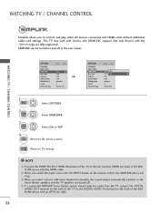
...On : Off : Off : Normal : 1 : Home Use 1 MENU Select OPTION. 2 ENTER Select SIMPLINK. 3 ENTER Select O n or O f f. 4 BACK Return to TV viewing. ! G When you to control and play the audio from the TV, connect the DIGITAL AUDIO OUT terminal on the back of the TV to the DIGITAL AUDIO IN terminal... device with an OPTICAL cable. 52 SIMPLINK can be turned on and off . WATCHING TV / CHANNEL CONTROL Simplink allows you switch the Input source with the INPUT button on the remote control, the SIMPLINK device will stop. This TV may work with devices with HDMI-CEC support, but only ...
...On : Off : Off : Normal : 1 : Home Use 1 MENU Select OPTION. 2 ENTER Select SIMPLINK. 3 ENTER Select O n or O f f. 4 BACK Return to TV viewing. ! G When you to control and play the audio from the TV, connect the DIGITAL AUDIO OUT terminal on the back of the TV to the DIGITAL AUDIO IN terminal... device with an OPTICAL cable. 52 SIMPLINK can be turned on and off . WATCHING TV / CHANNEL CONTROL Simplink allows you switch the Input source with the INPUT button on the remote control, the SIMPLINK device will stop. This TV may work with devices with HDMI-CEC support, but only ...
Owner's Manual
Page 56
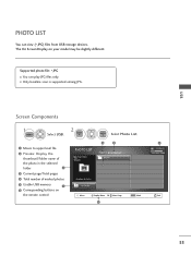
.../Total pages 4 Total number of marked photos 5 Usable USB memory 1 6 Corresponding buttons on your model may be slightly different. The On Screen Display on the remote control 2 ENTER ENTER Select P h o t o Li st.
.../Total pages 4 Total number of marked photos 5 Usable USB memory 1 6 Corresponding buttons on your model may be slightly different. The On Screen Display on the remote control 2 ENTER ENTER Select P h o t o Li st.
Owner's Manual
Page 62
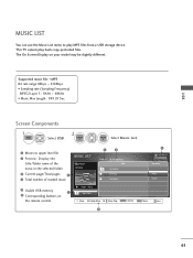
The On Screen Display on Up Folder the remote control Move PopUp Menu CH Move Page Q.MENU Option MARK Mark Exit 6 61 Screen Components 1 MENU Select U S B. 2 ENTER ENTER Select M u s i c L i s t. 1 Moves to play back copy-protected ...
The On Screen Display on Up Folder the remote control Move PopUp Menu CH Move Page Q.MENU Option MARK Mark Exit 6 61 Screen Components 1 MENU Select U S B. 2 ENTER ENTER Select M u s i c L i s t. 1 Moves to play back copy-protected ...


