Owner's Manual
Page 3
... interference received, including interference that the cable ground shall be determined by turning the equipment off and on a circuit different from LG Electronics. Reorient or relocate the receiving antenna. - Consult the dealer or an experienced radio/TV technician for proper grounding and, ... the device). Any changes or modifications not expressly approved by one or more of the building, as practical. This equipment generates, uses and can be connected to the grounding system of the following measures: - The code provides guidelines for help. CAUTION Do not...
... interference received, including interference that the cable ground shall be determined by turning the equipment off and on a circuit different from LG Electronics. Reorient or relocate the receiving antenna. - Consult the dealer or an experienced radio/TV technician for proper grounding and, ... the device). Any changes or modifications not expressly approved by one or more of the building, as practical. This equipment generates, uses and can be connected to the grounding system of the following measures: - The code provides guidelines for help. CAUTION Do not...

Owner's Manual
Page 4
...blades with the apparatus. Keep these instructions. When a cart is required when the apparatus has been damaged in accordance with the manufacturer's instructions. 8 Use only with the cart, stand, tripod, bracket, or table specified by the manufacturer. 3 Do not block any heat sources such as power- ... and the point where they exit from tip-over. 4 Do not install near water. 2 Clean only with soft dry cloth. 7 Only use caution when moving the cart/apparatus com- If the provided plug does not fit into the apparatus, the apparatus has been exposed to qualified service...
...blades with the apparatus. Keep these instructions. When a cart is required when the apparatus has been damaged in accordance with the manufacturer's instructions. 8 Use only with the cart, stand, tripod, bracket, or table specified by the manufacturer. 3 Do not block any heat sources such as power- ... and the point where they exit from tip-over. 4 Do not install near water. 2 Clean only with soft dry cloth. 7 Only use caution when moving the cart/apparatus com- If the provided plug does not fit into the apparatus, the apparatus has been exposed to qualified service...
Owner's Manual
Page 5
Periodically examine the cord of your appliance, and if its appearance indicates damage or deterioration, unplug it, discontinue use a damaged or loose power cord. Be sure do not expose this unit by SWITCH" 4 Do not pull on the power cord to plugs, wall .... When mounting a TV on the back of this product near flammable objects such as this apparatus or antenna during a thunder or lighting storm. Do not use of the appliance, and have a qualified electrician install a separate circuit breaker. that is, a single outlet circuit which powers only that you turn off this...
Periodically examine the cord of your appliance, and if its appearance indicates damage or deterioration, unplug it, discontinue use a damaged or loose power cord. Be sure do not expose this unit by SWITCH" 4 Do not pull on the power cord to plugs, wall .... When mounting a TV on the back of this product near flammable objects such as this apparatus or antenna during a thunder or lighting storm. Do not use of the appliance, and have a qualified electrician install a separate circuit breaker. that is, a single outlet circuit which powers only that you turn off this...
Owner's Manual
Page 7
... 17 Desktop Pedestal Installation 18 Swivel Stand 18 VESA Wall Mounting 19 Securing the TV to the wall to prevent falling when the TV is used on a stand 20 Antenna or Cable Connection 21 EXTERNAL EQUIPMENT SETUP HD Receiver Setup 22 DVD Setup 25 VCR Setup 27 Other A/V Source Setup 28...
... 17 Desktop Pedestal Installation 18 Swivel Stand 18 VESA Wall Mounting 19 Securing the TV to the wall to prevent falling when the TV is used on a stand 20 Antenna or Cable Connection 21 EXTERNAL EQUIPMENT SETUP HD Receiver Setup 22 DVD Setup 25 VCR Setup 27 Other A/V Source Setup 28...

Owner's Manual
Page 9
.... This TV contains the detailed calibrations necessary for a more pixels, 16:9 aspect-ratio screens, and AC3 digital audio. Using a sophisticated algorithm, the LG processes picture quality elements including brightness, contrast, color, sharpness and white balance. IMPORTANT INFORMATION TO PREVENT "IMAGE BURN / ...settings. I In order to prevent image burn, avoid displaying a fixed image on the letterboxed areas of ambient light, LG's "Intelligent Sensor" uses 4,096 sensing steps to offer. I Image burn can become permanently imprinted on your local dealer to help keep dialogue ...
.... This TV contains the detailed calibrations necessary for a more pixels, 16:9 aspect-ratio screens, and AC3 digital audio. Using a sophisticated algorithm, the LG processes picture quality elements including brightness, contrast, color, sharpness and white balance. IMPORTANT INFORMATION TO PREVENT "IMAGE BURN / ...settings. I In order to prevent image burn, avoid displaying a fixed image on the letterboxed areas of ambient light, LG's "Intelligent Sensor" uses 4,096 sensing steps to offer. I Image burn can become permanently imprinted on your local dealer to help keep dialogue ...

Owner's Manual
Page 10
... signal interface cables with the polishing cloth. models.) AUDIO IN (RGB/DVI) Ferrite core can be used to AUDIO IN(RGB/DVI) jack on the exterior only with ferrite cores to the wall plug. 9 available for stand assembly (Refer to the wall ... reduce the electromag- Install the Ferrite core on the display. If an accessory is not close to reduce the elec- The ferrite core can be used to AUDIO IN(RGB/DVI) jack available for all models.) Place the ferrite core close to maintain standards compliance. PREPARATION PREPARATION ACCESSORIES Ensure that may...
... signal interface cables with the polishing cloth. models.) AUDIO IN (RGB/DVI) Ferrite core can be used to AUDIO IN(RGB/DVI) jack on the exterior only with ferrite cores to the wall plug. 9 available for stand assembly (Refer to the wall ... reduce the electromag- Install the Ferrite core on the display. If an accessory is not close to reduce the elec- The ferrite core can be used to AUDIO IN(RGB/DVI) jack available for all models.) Place the ferrite core close to maintain standards compliance. PREPARATION PREPARATION ACCESSORIES Ensure that may...
Owner's Manual
Page 14
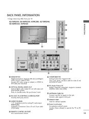
... Cord Socket For operation with amps and home theater systems. Note: In standby mode, this port doesn't work. 3 RS-232C IN (CONTROL & SERVICE) PORT Used by third party devices. 4 AUDIO IN (RGB) 1/8" headphone jack for analog PC audio input. Caution: Never attempt to DVI cable (not included) 2 OPTICAL... standard definition video only (480i). 8 ANTENNA/CABLE IN Connect over-the air signals to this jack. Accepts DVI video using an adapter or HDMI to operate the TV on DC power. 13 Uses a D-sub 15 pin cable (VGA cable). 5 REMOTE CONTROL IN PORT For a wired remote control. 6 COMPONENT IN...
... Cord Socket For operation with amps and home theater systems. Note: In standby mode, this port doesn't work. 3 RS-232C IN (CONTROL & SERVICE) PORT Used by third party devices. 4 AUDIO IN (RGB) 1/8" headphone jack for analog PC audio input. Caution: Never attempt to DVI cable (not included) 2 OPTICAL... standard definition video only (480i). 8 ANTENNA/CABLE IN Connect over-the air signals to this jack. Accepts DVI video using an adapter or HDMI to operate the TV on DC power. 13 Uses a D-sub 15 pin cable (VGA cable). 5 REMOTE CONTROL IN PORT For a wired remote control. 6 COMPONENT IN...
Owner's Manual
Page 15
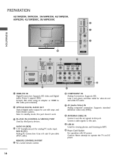
...standard definition video only (480i). 8 ANTENNA/CABLE IN Connect over-the air signals to operate the TV on DC power. 14 Uses a D-sub 15 pin cable (VGA cable). Uses a red, green, and blue cable for video & red and white for analog PC audio input. AUDIO IN (RGB) 4 ...COMPONENT IN Analog Connection. Connect cable signals to this jack. Supports HD video and Digital audio. R VIDEO L/MONO AUDIO R HDMI IN 3 USB IN R R PREPARATION 42/50PJ350, 50PK350, 50/60PK550, 42/50PJ550, 60PK290, 42/50PJ350C, 50/60PK550C 9 1 PREPARATION 7 10 AV IN 2 2 4 5 7 OPTICAL DIGITAL AUDIO OUT AUDIO IN (RGB...
...standard definition video only (480i). 8 ANTENNA/CABLE IN Connect over-the air signals to operate the TV on DC power. 14 Uses a D-sub 15 pin cable (VGA cable). Uses a red, green, and blue cable for video & red and white for analog PC audio input. AUDIO IN (RGB) 4 ...COMPONENT IN Analog Connection. Connect cable signals to this jack. Supports HD video and Digital audio. R VIDEO L/MONO AUDIO R HDMI IN 3 USB IN R R PREPARATION 42/50PJ350, 50PK350, 50/60PK550, 42/50PJ550, 60PK290, 42/50PJ350C, 50/60PK550C 9 1 PREPARATION 7 10 AV IN 2 2 4 5 7 OPTICAL DIGITAL AUDIO OUT AUDIO IN (RGB...
Owner's Manual
Page 16
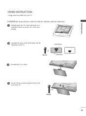
x 3 M5x14 Stand Body Stand Base 3 Assemble the TV as shown. 4 Fix the 4 bolts securely using the holes in the back of the TV. Installation (Except 60PK250, 60PK540, 60PK550, 60PK280, 60PK290, 60PK550C) 1 Carefully place the TV screen side down on a cushioned surface to protect the screen from your TV. x 4 M4x28 15 PREPARATION STAND INSTRUCTION I Image shown may differ from damage. 2 Assemble the parts of the Stand Body with the Stand Base of the TV.
x 3 M5x14 Stand Body Stand Base 3 Assemble the TV as shown. 4 Fix the 4 bolts securely using the holes in the back of the TV. Installation (Except 60PK250, 60PK540, 60PK550, 60PK280, 60PK290, 60PK550C) 1 Carefully place the TV screen side down on a cushioned surface to protect the screen from your TV. x 4 M4x28 15 PREPARATION STAND INSTRUCTION I Image shown may differ from damage. 2 Assemble the parts of the Stand Body with the Stand Base of the TV.
Owner's Manual
Page 20
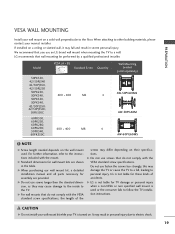
...the inside to follow the TV installation instructions. Do not use screws that do not comply with the mount. When attaching to the floor. Model VESA (A * B) A Standard Screw Quantity B Wall Mounting bracket (sold separately) 50PK550, 42/50PJ340 42/50PJ350, 42/50PJ250 50PK250, 50PK340, 400 * 400 M6 .... G When purchasing our wall mount kit, a detailed installation manual and all parts necessary for wall mount kits are provided. LG recommends that you use screws longer then the standard dimension, as they may damage the TV or cause the TV to a fall and result in ...
...the inside to follow the TV installation instructions. Do not use screws that do not comply with the mount. When attaching to the floor. Model VESA (A * B) A Standard Screw Quantity B Wall Mounting bracket (sold separately) 50PK550, 42/50PJ340 42/50PJ350, 42/50PJ250 50PK250, 50PK340, 400 * 400 M6 .... G When purchasing our wall mount kit, a detailed installation manual and all parts necessary for wall mount kits are provided. LG recommends that you use screws longer then the standard dimension, as they may damage the TV or cause the TV to a fall and result in ...
Owner's Manual
Page 21
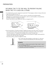
... to the wall. I Insert the eye-bolts (or TV brackets and bolts) to tighten the product to a wall so it cannot fall over (when not using a wall mount). We recommend that the TV be attached to the wall as shown in the picture. * If your TV. Ensure the eye-bolts or... the height of the bracket on the wall and the one on the TV are tightened securely. I Image shown may differ from the TV. NOTE G Use a platform or cabinet strong enough and large enough to support the size and weight of the bracket that children don't climb on the wall to...
... to the wall. I Insert the eye-bolts (or TV brackets and bolts) to tighten the product to a wall so it cannot fall over (when not using a wall mount). We recommend that the TV be attached to the wall as shown in the picture. * If your TV. Ensure the eye-bolts or... the height of the bracket on the wall and the one on the TV are tightened securely. I Image shown may differ from the TV. NOTE G Use a platform or cabinet strong enough and large enough to support the size and weight of the bracket that children don't climb on the wall to...
Owner's Manual
Page 23
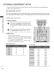
... the video outputs (Y, PB, PR) of the digital set -top box or other digital external device, refer to the figure as shown below. How to use I Turn on the digital set-top box. (Refer to the COMPONENT IN VIDEO 1 jacks on the TV. 2. operation) I Select the Component1 input source on... the TV using the INPUT button on the TV. 1 2 O IN /DVI) REMOTE CONTROL IN AV IN 1 VIDEO /MONO AUDIO 2 L R 1 VIDEO AUDIO COMPONENT IN ANT CA Supported Resolutions ...
... the video outputs (Y, PB, PR) of the digital set -top box or other digital external device, refer to the figure as shown below. How to use I Turn on the digital set-top box. (Refer to the COMPONENT IN VIDEO 1 jacks on the TV. 2. operation) I Select the Component1 input source on... the TV using the INPUT button on the TV. 1 2 O IN /DVI) REMOTE CONTROL IN AV IN 1 VIDEO /MONO AUDIO 2 L R 1 VIDEO AUDIO COMPONENT IN ANT CA Supported Resolutions ...
Owner's Manual
Page 24
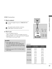
... to HDMI/DVI IN 1, 2 or 3 No separate audio connection is necessary. 2 HDMI supports both audio and video. 2. In this case use I Select the HDMI1, 2 or 3 input source on the TV using the INPUT button on the digital set-top box. (Refer to the owner's manual for the digital set -top box to... use the latest cables that support HDMI version 1.3. NOTE G Check HDMI cable over version 1.3. HDMI-DTV Resolution Horizontal Vertical Frequency(KHz) Frequency(Hz) 720x480p 1280x720p 1920x1080i ...
... to HDMI/DVI IN 1, 2 or 3 No separate audio connection is necessary. 2 HDMI supports both audio and video. 2. In this case use I Select the HDMI1, 2 or 3 input source on the TV using the INPUT button on the digital set-top box. (Refer to the owner's manual for the digital set -top box to... use the latest cables that support HDMI version 1.3. NOTE G Check HDMI cable over version 1.3. HDMI-DTV Resolution Horizontal Vertical Frequency(KHz) Frequency(Hz) 720x480p 1280x720p 1920x1080i ...
Owner's Manual
Page 25
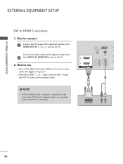
NOTE G A DVI to HDMI Connection 1. How to use I Select the HDMI1, 2 or 3 input source on the TV using the INPUT button on the remote control. ! OPTICAL DIGITAL AUDIO OUT AUDIO IN (RGB/DVI) R CO RS-232C IN (CONTROL & SERVICE) RGB IN (PC) 2 2 1 1 HDMI/...
NOTE G A DVI to HDMI Connection 1. How to use I Select the HDMI1, 2 or 3 input source on the TV using the INPUT button on the remote control. ! OPTICAL DIGITAL AUDIO OUT AUDIO IN (RGB/DVI) R CO RS-232C IN (CONTROL & SERVICE) RGB IN (PC) 2 2 1 1 HDMI/...
Owner's Manual
Page 26
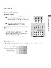
...IN AUDIO 1 jacks on DVD player Y Y PB PR PB PR B-Y R-Y Cb Cr Pb Pr 25 I Select the Component1 input source on the TV using the INPUT button on the TV. Y PB PR L R 2 Connect the audio outputs of the DVD to the component input ports as shown below. ... connect 1 Connect the video outputs (Y, PB, PR) of the DVD to COMPONENT IN 2 input, select the Component2 input source on the remote control. How to use I Refer to the DVD player's manual for operating instructions. 1 2 DIO IN B/DVI) REMOTE CONTROL IN AV IN 1 VIDEO /MONO AUDIO 2 L R 1 VIDEO AUDIO ...
...IN AUDIO 1 jacks on DVD player Y Y PB PR PB PR B-Y R-Y Cb Cr Pb Pr 25 I Select the Component1 input source on the TV using the INPUT button on the TV. Y PB PR L R 2 Connect the audio outputs of the DVD to the component input ports as shown below. ... connect 1 Connect the video outputs (Y, PB, PR) of the DVD to COMPONENT IN 2 input, select the Component2 input source on the remote control. How to use I Refer to the DVD player's manual for operating instructions. 1 2 DIO IN B/DVI) REMOTE CONTROL IN AV IN 1 VIDEO /MONO AUDIO 2 L R 1 VIDEO AUDIO ...
Owner's Manual
Page 27
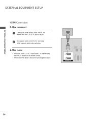
How to use I Refer to the HDMI/DVI IN 1, 2 or 3 jack on the remote control. EXTERNAL EQUIPMENT SETUP EXTERNAL EQUIPMENT SETUP HDMI Connection 1. I Select the HDMI1, 2 or 3 input source on the TV using the INPUT button on the TV. 2 No separate audio connection is necessary. HDMI-DVD OUTPUT 1 OPTICAL DIGITAL AUDIO OUT AUD (RGB/D 2 1 HDMI/DVI IN RS-232C IN (CONTROL & SERVICE) RGB IN (PC) 26 HDMI supports both audio and video. 2. How to connect 1 Connect the HDMI output of the DVD to the DVD player's manual for operating instructions.
How to use I Refer to the HDMI/DVI IN 1, 2 or 3 jack on the remote control. EXTERNAL EQUIPMENT SETUP EXTERNAL EQUIPMENT SETUP HDMI Connection 1. I Select the HDMI1, 2 or 3 input source on the TV using the INPUT button on the TV. 2 No separate audio connection is necessary. HDMI-DVD OUTPUT 1 OPTICAL DIGITAL AUDIO OUT AUD (RGB/D 2 1 HDMI/DVI IN RS-232C IN (CONTROL & SERVICE) RGB IN (PC) 26 HDMI supports both audio and video. 2. How to connect 1 Connect the HDMI output of the DVD to the DVD player's manual for operating instructions.
Owner's Manual
Page 28
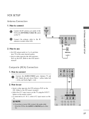
... AV IN 2, select AV2 input source on the VCR. (Refer to the AUDIO L/MONO jack of the VCR. 2. I Select the A V 1 input source on the TV using the INPUT button on the TV. EXTERNAL EQUIPMENT SETUP VCR SETUP Antenna Connection 1. NOTE G If you have a mono VCR, connect the audio cable from the... Wall Jack Antenna Composite (RCA) Connection 1. How to connect 1 Connect the RF antenna out socket of the VCR to the same channel number. How to use I Set VCR output switch to 3 or 4 and then tune TV to the ANTENNA/CABLE IN socket on the remote control. How to...
... AV IN 2, select AV2 input source on the VCR. (Refer to the AUDIO L/MONO jack of the VCR. 2. I Select the A V 1 input source on the TV using the INPUT button on the TV. EXTERNAL EQUIPMENT SETUP VCR SETUP Antenna Connection 1. NOTE G If you have a mono VCR, connect the audio cable from the... Wall Jack Antenna Composite (RCA) Connection 1. How to connect 1 Connect the RF antenna out socket of the VCR to the same channel number. How to use I Set VCR output switch to 3 or 4 and then tune TV to the ANTENNA/CABLE IN socket on the remote control. How to...
Owner's Manual
Page 29
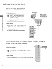
...50PJ350, 50PK350, 42/50PJ550, 50/60PK550, 60PK290, 42/50PJ350C, 50/60PK550C models 1. How to AV IN 1 input, select the A V 1 input source on the TV. I Select the A V 2 input source on the TV using the INPUT button on the side of TV. 2. How to connect i.e) 1 1 Connect the USB device to use... I After connecting the USB I N jack, you use I If connected to use the USB function. (G p.54) AV IN 2 28 USB IN Camcorder Video Game Set VIDEO L R 1 EXTERNAL EQUIPMENT SETUP VIDEO L/MONO AUDIO...
...50PJ350, 50PK350, 42/50PJ550, 50/60PK550, 60PK290, 42/50PJ350C, 50/60PK550C models 1. How to AV IN 1 input, select the A V 1 input source on the TV. I Select the A V 2 input source on the TV using the INPUT button on the side of TV. 2. How to connect i.e) 1 1 Connect the USB device to use... I After connecting the USB I N jack, you use I If connected to use the USB function. (G p.54) AV IN 2 28 USB IN Camcorder Video Game Set VIDEO L R 1 EXTERNAL EQUIPMENT SETUP VIDEO L/MONO AUDIO...
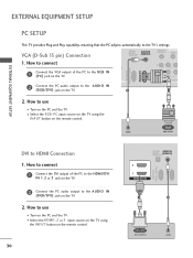
Owner's Manual
Page 31
... Play capability, meaning that the PC adjusts automatically to HDMI Connection 1. AUDIO RGB OUTPUT DVI to the TV's settings. How to use I Turn on the PC and the TV. How to use I Turn on the PC and the TV. How to connect 1 Connect the DVI output of the PC to the RGB... AUDIO IN (RGB/DVI) REMOTE CONTROL IN VIDEO RS-232C IN (CONTROL & SERVICE) RGB IN (PC) 1. I Select the RGB-PC input source on the TV using the INPUT button on the TV. 2. How to connect 2 1 Connect the VGA output of the PC to the HDMI/DVI IN 1, 2 or 3 jack on the...
... Play capability, meaning that the PC adjusts automatically to HDMI Connection 1. AUDIO RGB OUTPUT DVI to the TV's settings. How to use I Turn on the PC and the TV. How to use I Turn on the PC and the TV. How to connect 1 Connect the DVI output of the PC to the RGB... AUDIO IN (RGB/DVI) REMOTE CONTROL IN VIDEO RS-232C IN (CONTROL & SERVICE) RGB IN (PC) 1. I Select the RGB-PC input source on the TV using the INPUT button on the TV. 2. How to connect 2 1 Connect the VGA output of the PC to the HDMI/DVI IN 1, 2 or 3 jack on the...
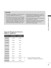
Owner's Manual
Page 32
... 47.712 60.015 1280x1024 63.981 60.020 1600x1200 74.537 59.869 1920x1080 66.587 59.934 Except 42/50PJ250, 42/50PJ340, 42/50PJ350, 42/50PJ550, 42/50PJ350C 31 G Avoid keeping a fixed image on the screen. G The synchronization input form for a long period of time. EXTERNAL EQUIPMENT SETUP ! NOTES... the graphics card, DOS mode may be positioned on the graphics card, some resolution settings may not allow the image to DVI Cable is in use.
... 47.712 60.015 1280x1024 63.981 60.020 1600x1200 74.537 59.869 1920x1080 66.587 59.934 Except 42/50PJ250, 42/50PJ340, 42/50PJ350, 42/50PJ550, 42/50PJ350C 31 G Avoid keeping a fixed image on the screen. G The synchronization input form for a long period of time. EXTERNAL EQUIPMENT SETUP ! NOTES... the graphics card, DOS mode may be positioned on the graphics card, some resolution settings may not allow the image to DVI Cable is in use.


