
Instructions
Page 2
Refer servicing to repair it yourself or remove the rear cover. Avoid Improper installation and never position the unit where good ventilation is intended to alert the user to the presence of trouble, unplug the unit and call a service technician. IMPORTANT RECYCLING INFORMATION This ...not use this polarized plug with arrowhead symbol, within an equilateral triangle is intended to alert the user to disconnect both the power plug from the power source specified on the unit. 2. Changes or modifications not approved by JVC could void the warranty. * When you don't use this TV set ...
Refer servicing to repair it yourself or remove the rear cover. Avoid Improper installation and never position the unit where good ventilation is intended to alert the user to the presence of trouble, unplug the unit and call a service technician. IMPORTANT RECYCLING INFORMATION This ...not use this polarized plug with arrowhead symbol, within an equilateral triangle is intended to alert the user to disconnect both the power plug from the power source specified on the unit. 2. Changes or modifications not approved by JVC could void the warranty. * When you don't use this TV set ...
Instructions
Page 3
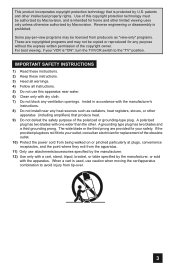
... sources such as "view-only" programs. These are provided for your VCR is prohibited. A polarized plug has two blades with dry cloth. 7) Do not block any ventilation openings. When a cart is used, use attachments/accessories specified by the manufacturer. 12) Use only with a cart, stand, tripod, bracket, or table specified by the manufacturer, or sold with the manufacturer's instructions. 8) Do not install...
... sources such as "view-only" programs. These are provided for your VCR is prohibited. A polarized plug has two blades with dry cloth. 7) Do not block any ventilation openings. When a cart is used, use attachments/accessories specified by the manufacturer. 12) Use only with a cart, stand, tripod, bracket, or table specified by the manufacturer, or sold with the manufacturer's instructions. 8) Do not install...

Instructions
Page 7
... hand to hold the edge of the panel and slowly adjust the direction of the TV stand. 7 This stand can be used to adjust the direction of the following items. In addition to this guide, your television box should include: 1 Television 1 Remote Control TV CATV VCR DVD POWER ASPECT MULTI SCREEN TWIN INDEX SELECT SLEEP FREEZE SWAP ML/MTS DISPLAY + INPUT 123 D/A 4 5 6 i.LINK MENU 7 TIMER TUNE THEATER FAVORITE PRO C.C. Before you begin...
... hand to hold the edge of the panel and slowly adjust the direction of the TV stand. 7 This stand can be used to adjust the direction of the following items. In addition to this guide, your television box should include: 1 Television 1 Remote Control TV CATV VCR DVD POWER ASPECT MULTI SCREEN TWIN INDEX SELECT SLEEP FREEZE SWAP ML/MTS DISPLAY + INPUT 123 D/A 4 5 6 i.LINK MENU 7 TIMER TUNE THEATER FAVORITE PRO C.C. Before you begin...

Instructions
Page 8
... is only for your specific TV and remote. AUDIO - AUDIO - L R AUDIO INPUT L S-VIDEO VIDEO OVER R - Quick Setup TV Models Before you in understanding how to connect your television to another device, please refer to set up your television. L Y Pr Pb S-VIDEO VIDEO OVER R - L RS-232C INPUT 1 FOR HDMI 1 AUDIO MOOUNTITOR / REC OUT Side Panel Diagram INPUT MENU + CHANNEL - + VOLUME - These will help assist you connect your television to another device, as well as use the remote to the proper diagrams for models LT-40FH97 and...
... is only for your specific TV and remote. AUDIO - AUDIO - L R AUDIO INPUT L S-VIDEO VIDEO OVER R - Quick Setup TV Models Before you in understanding how to connect your television to another device, please refer to set up your television. L Y Pr Pb S-VIDEO VIDEO OVER R - L RS-232C INPUT 1 FOR HDMI 1 AUDIO MOOUNTITOR / REC OUT Side Panel Diagram INPUT MENU + CHANNEL - + VOLUME - These will help assist you connect your television to another device, as well as use the remote to the proper diagrams for models LT-40FH97 and...
Instructions
Page 9
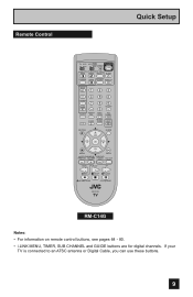
... PAUSE OPEN CLOSE STILL PAUSE RM-C14G RM-C14G Notes: • For information on remote control buttons, see pages 64 - 80. • i.LINK MENU, TIMER, SUB CHANNEL and GUIDE buttons are for digital channels. Remote Control Quick Setup TV CATV VCR DVD POWER ASPECT MULTI SCREEN TWIN INDEX SELECT SLEEP FREEZE SWAP ML/MTS DISPLAY + INPUT 123 D/A 4 5 6 i.LINK MENU 7 TIMER TUNE THEATER FAVORITE PRO C.C. If your TV is connected to an ATSC antenna or Digital Cable, you can use these buttons. 9
... PAUSE OPEN CLOSE STILL PAUSE RM-C14G RM-C14G Notes: • For information on remote control buttons, see pages 64 - 80. • i.LINK MENU, TIMER, SUB CHANNEL and GUIDE buttons are for digital channels. Remote Control Quick Setup TV CATV VCR DVD POWER ASPECT MULTI SCREEN TWIN INDEX SELECT SLEEP FREEZE SWAP ML/MTS DISPLAY + INPUT 123 D/A 4 5 6 i.LINK MENU 7 TIMER TUNE THEATER FAVORITE PRO C.C. If your TV is connected to an ATSC antenna or Digital Cable, you can use these buttons. 9

Instructions
Page 13
... connection setup does not work for DVD cables. Please consult the user's manual for your DVD player for more information. • Be careful not to Input 1. L S-VIDEO VIDEO OVER R - AUDIO - Quick Setup VCR Connection Notes: • Green, blue and red are the most common colors for you, try the connection setup on page 14. 13 Diagram #1 IN OUT V LR VCR IN OUT OR INPUT 3 Y Pr Pb VIDEO R - AUDIO - It is best to complete one set of connections (DVD or audio output...
... connection setup does not work for DVD cables. Please consult the user's manual for your DVD player for more information. • Be careful not to Input 1. L S-VIDEO VIDEO OVER R - AUDIO - Quick Setup VCR Connection Notes: • Green, blue and red are the most common colors for you, try the connection setup on page 14. 13 Diagram #1 IN OUT V LR VCR IN OUT OR INPUT 3 Y Pr Pb VIDEO R - AUDIO - It is best to complete one set of connections (DVD or audio output...

Instructions
Page 16
... use AUDIO OUTPUT for your TV. (See page 20). 2) When you have analog sound from an HDMI device connected to an External Amplifier TV Rear Panel S-VIDEO VIDEO OVER R - Notes: • Refer to your amplifier's manual for more information. • You can not output audio using the AUDIO OUTPUT under the following conditions: 1) When you have digital sound from a DVI device connected to the AUDIO IN "FOR HDMI 1" connection. (See page 19). 16 AUDIO - Quick Setup Connecting to the HDMI 1 or HDMI 2 connection...
... use AUDIO OUTPUT for your TV. (See page 20). 2) When you have analog sound from an HDMI device connected to an External Amplifier TV Rear Panel S-VIDEO VIDEO OVER R - Notes: • Refer to your amplifier's manual for more information. • You can not output audio using the AUDIO OUTPUT under the following conditions: 1) When you have digital sound from a DVI device connected to the AUDIO IN "FOR HDMI 1" connection. (See page 19). 16 AUDIO - Quick Setup Connecting to the HDMI 1 or HDMI 2 connection...

Instructions
Page 18
... television. 5) Connect a Red Component Cable from many different devices, without having to change or use the other devices like a DVD player. • Use your AV Receiver's remote to switch to the different devices you are using V1 Input as the V1 Smart Input. L INPUT 2 S-VIDEO VIDEO OVER R - L R INPUT MONITOR OUT Y PB PR MONITOR OUT DIO 1) Connect an S-Video Cable from the AV Receiver's MONITOR OUT, to the S-Video INPUT-1 on the back of your television. 2) Connect a Yellow Composite Cable from the AV Receiver's MONITOR...
... television. 5) Connect a Red Component Cable from many different devices, without having to change or use the other devices like a DVD player. • Use your AV Receiver's remote to switch to the different devices you are using V1 Input as the V1 Smart Input. L INPUT 2 S-VIDEO VIDEO OVER R - L R INPUT MONITOR OUT Y PB PR MONITOR OUT DIO 1) Connect an S-Video Cable from the AV Receiver's MONITOR OUT, to the S-Video INPUT-1 on the back of your television. 2) Connect a Yellow Composite Cable from the AV Receiver's MONITOR...

Instructions
Page 19
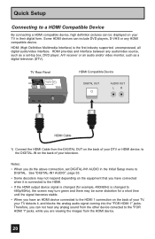
... Rear Panel DTV Decoder DIGITAL OUT AUDIO OUT L R FOR HDMI 1 TV Rear Panel R AUDIO INPUT L S-VIDEO VIDEO REC OUT HDMI to DVI Cable After the connections have been made to the HDMI 1 along with analog audio cables. 19 ANALOG / DIGITAL" menu setting on your television. 3) Connect a white cable from the DTV decoder LEFT AUDIO OUT, to the LEFT AUDIO INPUT "FOR HDMI 1" on the screen, the horizontal balance may be slightly shifted. Quick Setup Connecting to a Digital TV Receiver By connecting a Digital TV Receiver, high definition pictures can only be used with the HDMI 1 input...
... Rear Panel DTV Decoder DIGITAL OUT AUDIO OUT L R FOR HDMI 1 TV Rear Panel R AUDIO INPUT L S-VIDEO VIDEO REC OUT HDMI to DVI Cable After the connections have been made to the HDMI 1 along with analog audio cables. 19 ANALOG / DIGITAL" menu setting on your television. 3) Connect a white cable from the DTV decoder LEFT AUDIO OUT, to the LEFT AUDIO INPUT "FOR HDMI 1" on the screen, the horizontal balance may be slightly shifted. Quick Setup Connecting to a Digital TV Receiver By connecting a Digital TV Receiver, high definition pictures can only be used with the HDMI 1 input...
Instructions
Page 20
... do the above connection, set -top box, DVD player, A/V receiver or an audio and/or video monitor, such as a set DIGITAL-IN1 AUDIO in the Initial Setup menu to 480p/60Hz), the screen may turn green and there may not respond depending on your TV in their digital form. Therefore, you can not hear any analog sound from the other device conected to the "FOR HDMI 1" jacks, while you are viewing the images...
... do the above connection, set -top box, DVD player, A/V receiver or an audio and/or video monitor, such as a set DIGITAL-IN1 AUDIO in the Initial Setup menu to 480p/60Hz), the screen may turn green and there may not respond depending on your TV in their digital form. Therefore, you can not hear any analog sound from the other device conected to the "FOR HDMI 1" jacks, while you are viewing the images...
Instructions
Page 22
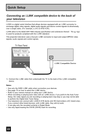
... i.LINK compatible device. If you may not be able to perform the Digital Auto Tuner Setup. • Your television can play only the recorded contents in Digital Mode. • Use only tapes bearing the DVHS (SVHS) mark for products compliant with i.LINK cable, they will not work. • It can connect with an i.LINK connector to your owners manual on using your television i.LINK is used for recording...
... i.LINK compatible device. If you may not be able to perform the Digital Auto Tuner Setup. • Your television can play only the recorded contents in Digital Mode. • Use only tapes bearing the DVHS (SVHS) mark for products compliant with i.LINK cable, they will not work. • It can connect with an i.LINK connector to your owners manual on using your television i.LINK is used for recording...

Instructions
Page 26
... may precisely set below. To set your clock manually (without using the XDS signal: SET CLOCK √® † To choose AUTO To TIME ZONE MODE TIME TIME ZONE DATE/YEAR D.S.T. You must first set the clock. ON or OFF To NEXT (To Auto Tuner Setup) SELECT OPERATE MENU EXIT Notes: • D.S.T. Quick Setup Auto Clock Set Before you use any of your TV's timer functions, you choose AUTO, see auto clock set above. NEXT AUTO -- : -- -- The clock...
... may precisely set below. To set your clock manually (without using the XDS signal: SET CLOCK √® † To choose AUTO To TIME ZONE MODE TIME TIME ZONE DATE/YEAR D.S.T. You must first set the clock. ON or OFF To NEXT (To Auto Tuner Setup) SELECT OPERATE MENU EXIT Notes: • D.S.T. Quick Setup Auto Clock Set Before you use any of your TV's timer functions, you choose AUTO, see auto clock set above. NEXT AUTO -- : -- -- The clock...

Instructions
Page 34
... PICTURE ADJUST 02 INITIAL SETUP PREVIOUS AUTO TUNER SETUP CHANNEL SUMMARY V-CHIP SET LOCK CODE NEXT PAGE SELECT OPERATE (4/5) MENU EXIT INITIAL SETUP 04 INITIAL SETUP PREVIOUS ILLUMINATION LOW LANGUAGE ENG. CLOSED CAPTION AUTO SHUT OFF OFF XDS ID ON NEXT PAGE SELECT OPERATE (3/5) MENU EXIT INITIAL SETUP 03 INITIAL SETUP PREVIOUS NOISE MUTING FRONT PANEL LOCK V1 SMART INPUT VIDEO INPUT LABEL POSITION ADJUSTMENT POWER INDICATOR NEXT PAGE SELECT OPERATE ON OFF ON LOW (2/5) MENU EXIT INITIAL SETUP 02 PICTURE ADJUST PREVIOUS DIGITAL...
... PICTURE ADJUST 02 INITIAL SETUP PREVIOUS AUTO TUNER SETUP CHANNEL SUMMARY V-CHIP SET LOCK CODE NEXT PAGE SELECT OPERATE (4/5) MENU EXIT INITIAL SETUP 04 INITIAL SETUP PREVIOUS ILLUMINATION LOW LANGUAGE ENG. CLOSED CAPTION AUTO SHUT OFF OFF XDS ID ON NEXT PAGE SELECT OPERATE (3/5) MENU EXIT INITIAL SETUP 03 INITIAL SETUP PREVIOUS NOISE MUTING FRONT PANEL LOCK V1 SMART INPUT VIDEO INPUT LABEL POSITION ADJUSTMENT POWER INDICATOR NEXT PAGE SELECT OPERATE ON OFF ON LOW (2/5) MENU EXIT INITIAL SETUP 02 PICTURE ADJUST PREVIOUS DIGITAL...
Instructions
Page 37
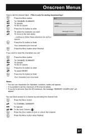
... of 40 channel labels. • If you try to set : π† √® π† π† Press the MENU button To CHANNEL SUMMARY To operate To the ID column Press the OK button to enter To select RESET Press the OK button to finish Your characters are now reset Notes: • You can block access to lock or unlock that channel Press the MENU button...
... of 40 channel labels. • If you try to set : π† √® π† π† Press the MENU button To CHANNEL SUMMARY To operate To the ID column Press the OK button to enter To select RESET Press the OK button to finish Your characters are now reset Notes: • You can block access to lock or unlock that channel Press the MENU button...

Instructions
Page 46
... analog channels, you can perform Digital Auto Setting or Digital Manual Setting. Analog Setting Press the MENU button π† √® π† √® π† √® To CLOSED CAPTION To enter To MODE To select CAPTION or TEXT in text form. To Service To select 1, 2, 3, 4, 5 or 6 To Appearance To enter To select Auto To Set Preview Closed Caption Sample Type Service Appearance AUTO 1 Cancel Select Set BACK Operate Back MENU Exit Digital Closed Caption > Appearance Preview Closed Caption...
... analog channels, you can perform Digital Auto Setting or Digital Manual Setting. Analog Setting Press the MENU button π† √® π† √® π† √® To CLOSED CAPTION To enter To MODE To select CAPTION or TEXT in text form. To Service To select 1, 2, 3, 4, 5 or 6 To Appearance To enter To select Auto To Set Preview Closed Caption Sample Type Service Appearance AUTO 1 Cancel Select Set BACK Operate Back MENU Exit Digital Closed Caption > Appearance Preview Closed Caption...
Instructions
Page 47
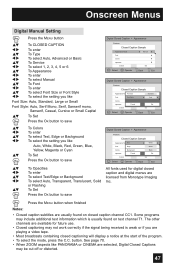
... licensed from Monotype Imaging Inc. See page 70. • When ZOOM aspects like Auto, White, Black, Red, Green, Blue, Yellow, Magenta or Cyan To Set Press the OK button to save Digital Closed Caption > Appearance Preview Closed Caption Sample Appearance ModeText Manual White Font Edge White Colors Background Black Opacities Cancel Set Cancel Set Select BACK Operate Back MENU Exit π† √® π† √® π† To...
... licensed from Monotype Imaging Inc. See page 70. • When ZOOM aspects like Auto, White, Black, Red, Green, Blue, Yellow, Magenta or Cyan To Set Press the OK button to save Digital Closed Caption > Appearance Preview Closed Caption Sample Appearance ModeText Manual White Font Edge White Colors Background Black Opacities Cancel Set Cancel Set Select BACK Operate Back MENU Exit π† √® π† √® π† To...

Instructions
Page 65
... Notes: • Only analog channel input signal will be displayed. • You can watch the channel added in TWIN mode. Button Functions Index This allows you to quickly look at up to 12 channels at a time so that you can decide which one of SELECT will only work in channel summary. Freeze Pressing the FREEZE button causes the screen to access JVC's onscreen menu system. In order to...
... Notes: • Only analog channel input signal will be displayed. • You can watch the channel added in TWIN mode. Button Functions Index This allows you to quickly look at up to 12 channels at a time so that you can decide which one of SELECT will only work in channel summary. Freeze Pressing the FREEZE button causes the screen to access JVC's onscreen menu system. In order to...

Instructions
Page 68
... natural cinema mode is displayed: Your SD settings are using the MENU button on film (such as an SD signal. VIDEO STATUS STANDARD DYNAMIC THEATER GAME Game - Each video status can not be chosen along with better contrast when viewing in a dimly lit room. It appears between INITIAL SETUP and PICTURE ADJUST screen, and it to the factory settings. buttons ( √ OPERATE ® ). • There are recalled for each input connected to "AUTO" in...
... natural cinema mode is displayed: Your SD settings are using the MENU button on film (such as an SD signal. VIDEO STATUS STANDARD DYNAMIC THEATER GAME Game - Each video status can not be chosen along with better contrast when viewing in a dimly lit room. It appears between INITIAL SETUP and PICTURE ADJUST screen, and it to the factory settings. buttons ( √ OPERATE ® ). • There are recalled for each input connected to "AUTO" in...

Instructions
Page 83
... input mode could be set . Move any analog sound from the HDMI device. (See page 20). PROBLEMS There is a problem, contact the JVC Service Center where you have digital sound from an HDMI device connected to the HDMI 1 or HDMI 2 connection on the back of your TV, your antenna position. See page 66. • The tuner (Auto Tuner Setup) could be set . See page 35. • The TV station may be improperly adjusted. Remote control is not operating properly...
... input mode could be set . Move any analog sound from the HDMI device. (See page 20). PROBLEMS There is a problem, contact the JVC Service Center where you have digital sound from an HDMI device connected to the HDMI 1 or HDMI 2 connection on the back of your TV, your antenna position. See page 66. • The tuner (Auto Tuner Setup) could be set . See page 35. • The TV station may be improperly adjusted. Remote control is not operating properly...

Instructions
Page 85
... to : http://software.jvc.com/opensource/lnx/DP/04_AtscCC/download.html * RS-232C is embedded in this product. See page 8. 85 Specifications Model LT-40FH97 LT-40FN97 LT-46FH97 LT-46FN97 Type Reception Format Reception Range Power Source Power Consumption Screen Size Audio Output Speakers Antenna Terminal (VHF/UHF, ATSC/DIGITAL CABLE IN) External Input Jacks Component Input Jack S-Video Input Jacks Monitor/Recording Output Optical Output Digital Audio PC Input Jack Digital-In LCD Flat Television NTSC, BTSC System (Multi-Channel Sound) ATSC Terrestrial, Digital Cable VHF 2 to...
... to : http://software.jvc.com/opensource/lnx/DP/04_AtscCC/download.html * RS-232C is embedded in this product. See page 8. 85 Specifications Model LT-40FH97 LT-40FN97 LT-46FH97 LT-46FN97 Type Reception Format Reception Range Power Source Power Consumption Screen Size Audio Output Speakers Antenna Terminal (VHF/UHF, ATSC/DIGITAL CABLE IN) External Input Jacks Component Input Jack S-Video Input Jacks Monitor/Recording Output Optical Output Digital Audio PC Input Jack Digital-In LCD Flat Television NTSC, BTSC System (Multi-Channel Sound) ATSC Terrestrial, Digital Cable VHF 2 to...


