
Instructions
Page 2
..., receptacle or other outlet unless the blades can be fully inserted to prevent blade exposure. • As an "ENERGY STAR®" partner, JVC has determined that may be sure to disconnect both the power plug from the power source specified on the unit. 2. No user serviceable parts ...inside. Changes or modifications not approved by JVC could void the warranty. * When you don't use this TV set for a long period of time, be of sufficient magnitude to constitute a risk of important operating and maintenance (servicing...
..., receptacle or other outlet unless the blades can be fully inserted to prevent blade exposure. • As an "ENERGY STAR®" partner, JVC has determined that may be sure to disconnect both the power plug from the power source specified on the unit. 2. No user serviceable parts ...inside. Changes or modifications not approved by JVC could void the warranty. * When you don't use this TV set for a long period of time, be of sufficient magnitude to constitute a risk of important operating and maintenance (servicing...
Instructions
Page 4
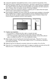
... Apparatus shall not be placed on the apparatus. 16) Avoid improper installation and never position the unit where good ventilation is available around the TV to allow satisfactory cooling. 18) Make enough room for long periods of time. 14) Refer all the LED lamps are not lit. The...Keep to keep cords out of furniture. 13) Unplug this apparatus during operation. Ensure that sufficient space is impossible. To shut down the TV, unplug the TV from the wall outlet. 4 Servicing is required when the apparatus has been damaged in a corner on standby even when all servicing to ...
... Apparatus shall not be placed on the apparatus. 16) Avoid improper installation and never position the unit where good ventilation is available around the TV to allow satisfactory cooling. 18) Make enough room for long periods of time. 14) Refer all the LED lamps are not lit. The...Keep to keep cords out of furniture. 13) Unplug this apparatus during operation. Ensure that sufficient space is impossible. To shut down the TV, unplug the TV from the wall outlet. 4 Servicing is required when the apparatus has been damaged in a corner on standby even when all servicing to ...
Instructions
Page 5
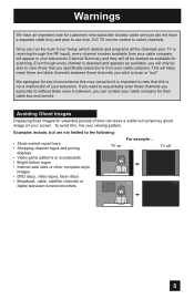
...We apologize for any inconvenience this may cause but it is receiving through the RF input), every channel number available from your screen. TV on your cable company. Avoiding Ghost Images Displaying fixed images for extended periods of your television's Channel Summary and they will ... not a malfunction of time can contact your viewing pattern. To avoid this is detected and appears as available for their JVC TV remote control to sequentially scan those that this , mix your cable company for scanning. Examples include, but temporary ghost image on...
...We apologize for any inconvenience this may cause but it is receiving through the RF input), every channel number available from your screen. TV on your cable company. Avoiding Ghost Images Displaying fixed images for extended periods of your television's Channel Summary and they will ... not a malfunction of time can contact your viewing pattern. To avoid this is detected and appears as available for their JVC TV remote control to sequentially scan those that this , mix your cable company for scanning. Examples include, but temporary ghost image on...
Instructions
Page 6
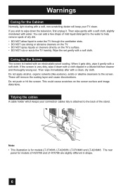
... cloth. Do not apply alcohol, organic solvents (like acetone), acidic or alkaline cleansers to enter the TV through the ventilation slots. • DO NOT use strong or abrasive cleaners on the TV. • DO NOT spray liquids or cleaners directly on the screen surface and image distortions. These ...oily dirt. • DO NOT allow liquid to the screen. If you wish to wipe down with water. The rear panel for models LT-42X788 and LT-47X788 are slightly different in a diluted kitchen cleaner and thoroughly wrung-out. Warnings Caring for the Cabinet Normally, light dusting with a soft,...
... cloth. Do not apply alcohol, organic solvents (like acetone), acidic or alkaline cleansers to enter the TV through the ventilation slots. • DO NOT use strong or abrasive cleaners on the TV. • DO NOT spray liquids or cleaners directly on the screen surface and image distortions. These ...oily dirt. • DO NOT allow liquid to the screen. If you wish to wipe down with water. The rear panel for models LT-42X788 and LT-47X788 are slightly different in a diluted kitchen cleaner and thoroughly wrung-out. Warnings Caring for the Cabinet Normally, light dusting with a soft,...

Instructions
Page 7
Note: • To re-install the stand, reverse the procedure from the TV. 4) Cover the hole with a bottom cover and tighten the screw. Warnings Disconnecting the stand If you disconnect the stand, attach the bottom cover and the screw (supplied) into the hole. This illustration is for models LT-42X788 and LT-47X788 using the same method. 1) Place the TV face down on a soft cloth on a table. 2) Remove the four screws from the back of the TV. 3) Pull out the stand from 4) to 1). 7 You can disconnect the stand for models LT-37X688, LT-42X688, LT-37XM48 and LT-42XM48.
Note: • To re-install the stand, reverse the procedure from the TV. 4) Cover the hole with a bottom cover and tighten the screw. Warnings Disconnecting the stand If you disconnect the stand, attach the bottom cover and the screw (supplied) into the hole. This illustration is for models LT-42X788 and LT-47X788 using the same method. 1) Place the TV face down on a soft cloth on a table. 2) Remove the four screws from the back of the TV. 3) Pull out the stand from 4) to 1). 7 You can disconnect the stand for models LT-37X688, LT-42X688, LT-37XM48 and LT-42XM48.

Instructions
Page 9
... read this guide, your television box should include: Television x 1 POWER + AA Alkaline - + AA Alkaline - BACK F Remote Control x 1 POWER MODE TV STB VCR DVD AUDIO INPUT V1 V2 V3 V4 V5 1 2 3 4 5 6 7 8 9 RETURN + TUNE 0 TV - SUB T. Before you begin setting up your new television, please check to make sure you for your purchase of...'s Guide so you 're anxious to start using your television right away, a quick setup guide follows on the next few pages. 9 Quick Setup Unpacking your TV Thank you have all of a JVC LCD Flat Television.
... read this guide, your television box should include: Television x 1 POWER + AA Alkaline - + AA Alkaline - BACK F Remote Control x 1 POWER MODE TV STB VCR DVD AUDIO INPUT V1 V2 V3 V4 V5 1 2 3 4 5 6 7 8 9 RETURN + TUNE 0 TV - SUB T. Before you begin setting up your new television, please check to make sure you for your purchase of...'s Guide so you 're anxious to start using your television right away, a quick setup guide follows on the next few pages. 9 Quick Setup Unpacking your TV Thank you have all of a JVC LCD Flat Television.

Instructions
Page 10
... 2 DIGITAL AUDIO OPTICAL OUT X688 and XM48 series INPUT X788 series MENU INPUT MENU C H CHANNEL OK VOLUME BACK POWER VOL OK BACK POWER Quick Setup TV Models Before you in understanding how to connect your television to another device, please refer to set up your specific...
... 2 DIGITAL AUDIO OPTICAL OUT X688 and XM48 series INPUT X788 series MENU INPUT MENU C H CHANNEL OK VOLUME BACK POWER VOL OK BACK POWER Quick Setup TV Models Before you in understanding how to connect your television to another device, please refer to set up your specific...
Instructions
Page 11
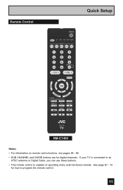
... DVR STATUS SOUND VIDEO ASPECT GUIDE SUB CH TV/VCR C.C. If your TV is connected to program the remote control. 11 Remote Control MENU Quick Setup POWER MODE TV STB VCR DVD AUDIO INPUT V1 V2 V3 V4 V5 1 2 3 4 5 6 7 8 9 RETURN + TUNE 0 TV - See page 67 - 72 for digital ...channels. DISPLAY SLEEP ML/MTS RM-C1450 TV RM-C1450 Notes: • For information on remote control...
... DVR STATUS SOUND VIDEO ASPECT GUIDE SUB CH TV/VCR C.C. If your TV is connected to program the remote control. 11 Remote Control MENU Quick Setup POWER MODE TV STB VCR DVD AUDIO INPUT V1 V2 V3 V4 V5 1 2 3 4 5 6 7 8 9 RETURN + TUNE 0 TV - See page 67 - 72 for digital ...channels. DISPLAY SLEEP ML/MTS RM-C1450 TV RM-C1450 Notes: • For information on remote control...

Instructions
Page 12
... in the unit first. Basic Operation Turn the television on and off by pressing the MODE button on the remote control before you turn the TV power on any of these steps, please consult other sections of the remote. If you have to complete the task within three minutes. Insert two... four arrow keys OK are turning on the remote's back cover to remove. Raise the latch on the TV, the interactive plug-in menu appears. • At first, to watch your TV, select the TV mode by pressing the POWER button at the top right corner of this is the first time you...
... in the unit first. Basic Operation Turn the television on and off by pressing the MODE button on the remote control before you turn the TV power on any of these steps, please consult other sections of the remote. If you have to complete the task within three minutes. Insert two... four arrow keys OK are turning on the remote's back cover to remove. Raise the latch on the TV, the interactive plug-in menu appears. • At first, to watch your TV, select the TV mode by pressing the POWER button at the top right corner of this is the first time you...
Instructions
Page 13
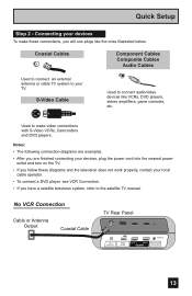
...diagrams are examples. • After you are finished connecting your devices, plug the power cord into the nearest power outlet and turn on the TV. • If you will use plugs like VCRs, DVD players, stereo amplifiers, game consoles, etc. Quick Setup Step 2 - Coaxial Cables... Component Cables Composite Cables Audio Cables Used to connect an external antenna or cable TV system to make these connections, you follow these diagrams and the television does not work properly, contact your devices To make video connections with...
...diagrams are examples. • After you are finished connecting your devices, plug the power cord into the nearest power outlet and turn on the TV. • If you will use plugs like VCRs, DVD players, stereo amplifiers, game consoles, etc. Quick Setup Step 2 - Coaxial Cables... Component Cables Composite Cables Audio Cables Used to connect an external antenna or cable TV system to make these connections, you follow these diagrams and the television does not work properly, contact your devices To make video connections with...
Instructions
Page 14
... PB L PR R INPUT 4 INPUT 5 / INPUT 1 AUDIO AUDIO OUT Y VIDEO VIDEO PB L L L PR R R R 75 Ω (VHF/UHF) PHOTO VIEWER INPUT 1 SERVICE INPUT 2 DIGITAL AUDIO OPTICAL OUT TV Rear Panel Green Blue Red Y PB PR OUT AUDIO OUT R L DVD Player Note: • If this connection setup does not work for DVD cables. Quick...
... PB L PR R INPUT 4 INPUT 5 / INPUT 1 AUDIO AUDIO OUT Y VIDEO VIDEO PB L L L PR R R R 75 Ω (VHF/UHF) PHOTO VIEWER INPUT 1 SERVICE INPUT 2 DIGITAL AUDIO OPTICAL OUT TV Rear Panel Green Blue Red Y PB PR OUT AUDIO OUT R L DVD Player Note: • If this connection setup does not work for DVD cables. Quick...

Instructions
Page 15
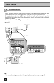
Diagram #2 R LV IN OUT VCR IN OUT OR Quick Setup Cable or Antenna Output IN Two-Way Splitter OUT OUT (Not supplied) Coaxial Cable AUDIO AUDIO AUDIO COMPONENT AUDIO COMPONENT INPUT 3 S-VIDEO Y VIDEO PB L PR R INPUT 4 INPUT 5 / INPUT 1 AUDIO AUDIO OUT Y VIDEO VIDEO PB L L L PR R R R Green Blue Red Y PB PR OUT AUDIO OUT R L DVD Player 75 Ω (VHF/UHF) PHOTO VIEWER INPUT 1 SERVICE INPUT 2 DIGITAL AUDIO OPTICAL OUT TV Rear Panel 15
Diagram #2 R LV IN OUT VCR IN OUT OR Quick Setup Cable or Antenna Output IN Two-Way Splitter OUT OUT (Not supplied) Coaxial Cable AUDIO AUDIO AUDIO COMPONENT AUDIO COMPONENT INPUT 3 S-VIDEO Y VIDEO PB L PR R INPUT 4 INPUT 5 / INPUT 1 AUDIO AUDIO OUT Y VIDEO VIDEO PB L L L PR R R R Green Blue Red Y PB PR OUT AUDIO OUT R L DVD Player 75 Ω (VHF/UHF) PHOTO VIEWER INPUT 1 SERVICE INPUT 2 DIGITAL AUDIO OPTICAL OUT TV Rear Panel 15
Instructions
Page 16
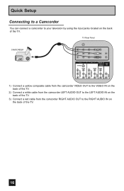
Quick Setup Connecting to a Camcorder You can connect a camcorder to the RIGHT AUDIO IN on the back of the TV. 16 TV Rear Panel CAMCORDER INPUT 3 S-VIDEO Y VIDEO PB L PR R INPUT 4 INPUT 5 / INPUT 1 AUDIO AUDIO OUT Y VIDEO VIDEO PB L L L PR R R R AUDIO AUDIO AUDIO COMPONENT AUDIO COMPONENT 1) Connect a... yellow composite cable from the camcorder VIDEO OUT to the VIDEO IN on the back of the TV. 2) Connect a white cable from the camcorder LEFT AUDIO OUT to the LEFT AUDIO IN on the back of the...
Quick Setup Connecting to a Camcorder You can connect a camcorder to the RIGHT AUDIO IN on the back of the TV. 16 TV Rear Panel CAMCORDER INPUT 3 S-VIDEO Y VIDEO PB L PR R INPUT 4 INPUT 5 / INPUT 1 AUDIO AUDIO OUT Y VIDEO VIDEO PB L L L PR R R R AUDIO AUDIO AUDIO COMPONENT AUDIO COMPONENT 1) Connect a... yellow composite cable from the camcorder VIDEO OUT to the VIDEO IN on the back of the TV. 2) Connect a white cable from the camcorder LEFT AUDIO OUT to the LEFT AUDIO IN on the back of the...
Instructions
Page 17
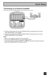
... will not be able to hear any audio from the RIGHT AUDIO OUTPUT on the back of the TV to the RIGHT AUDIO INPUT on the back of the TV to an External Amplifier TV Rear Panel Speaker Amplifier Speaker INPUT 3 S-VIDEO Y VIDEO PB L PR R INPUT 4 INPUT 5 / INPUT 1 AUDIO AUDIO OUT Y VIDEO VIDEO...
... will not be able to hear any audio from the RIGHT AUDIO OUTPUT on the back of the TV to the RIGHT AUDIO INPUT on the back of the TV to an External Amplifier TV Rear Panel Speaker Amplifier Speaker INPUT 3 S-VIDEO Y VIDEO PB L PR R INPUT 4 INPUT 5 / INPUT 1 AUDIO AUDIO OUT Y VIDEO VIDEO...
Instructions
Page 18
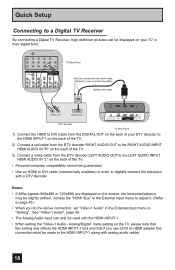
... screen, the horizontal balance may be slightly shifted. See "Video-1 Audio", page 45. • The Analog Audio input can be displayed on the TV, please note that this setting only effects the HDMI INPUT-1 jack and that if you do the above connection, set "Video-1 Audio" in their ...digital form. Quick Setup Connecting to a Digital TV Receiver By connecting a Digital TV Receiver, high definition pictures can only be used with the HDMI INPUT-1. • When setting the "Video-1 Audio - Access the "HDMI Size...
... screen, the horizontal balance may be slightly shifted. See "Video-1 Audio", page 45. • The Analog Audio input can be displayed on the TV, please note that this setting only effects the HDMI INPUT-1 jack and that if you do the above connection, set "Video-1 Audio" in their ...digital form. Quick Setup Connecting to a Digital TV Receiver By connecting a Digital TV Receiver, high definition pictures can only be used with the HDMI INPUT-1. • When setting the "Video-1 Audio - Access the "HDMI Size...
Instructions
Page 19
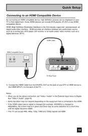
... screen may turn green and there may not respond depending on your DTV or HDMI device to the HDMI INPUT-1 on the back of your TV in the External Input menu to Digital. See "Video-1 Audio", page 45. • Some decoders may be displayed on the equipment that is connected...Compatible Device By connecting an HDMI compatible device, high definition pictures can be some distortion for a short time until the signal becomes stable. • This TV can accept 480i, 480p, 720p, 1080i and 1080p signals via HDMI. 19 Some HDMI devices can include DVD players, D-VHS or any audio/video ...
... screen may turn green and there may not respond depending on your DTV or HDMI device to the HDMI INPUT-1 on the back of your TV in the External Input menu to Digital. See "Video-1 Audio", page 45. • Some decoders may be displayed on the equipment that is connected...Compatible Device By connecting an HDMI compatible device, high definition pictures can be some distortion for a short time until the signal becomes stable. • This TV can accept 480i, 480p, 720p, 1080i and 1080p signals via HDMI. 19 Some HDMI devices can include DVD players, D-VHS or any audio/video ...
Instructions
Page 20
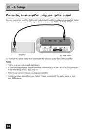
... using your optical output You can be PCM or DOLBY DIGITAL. 75 Ω (VHF/UHF) PHOTO VIEWER INPUT 1 SERVICE INPUT 2 DIGITAL AUDIO OPTICAL OUT Amplifier TV Rear Panel 1) Connect the optical cable from underneath the television to your HDMI device. 20
... using your optical output You can be PCM or DOLBY DIGITAL. 75 Ω (VHF/UHF) PHOTO VIEWER INPUT 1 SERVICE INPUT 2 DIGITAL AUDIO OPTICAL OUT Amplifier TV Rear Panel 1) Connect the optical cable from underneath the television to your HDMI device. 20

Instructions
Page 21
... input connections so you can watch picture sources from the AV Receiver's PR MONITOR OUT, into the PB VIDEO INPUT-3 on the back of the TV. TV Rear Panel AV Receiver MONITOR OUT Y PB PR MONITOR OUT INPUT 3 S-VIDEO Y VIDEO INPUT 4 Y VIDEO VIDEO PB L PB L L L PR R PR R R R AUDIO AUDIO AUDIO ... a Blue Component Cable from the AV Receiver's PB MONITOR OUT, into the PR VIDEO INPUT-3 on the back of the TV. 5) Connect a Red Component Cable from many different devices, without having to change or use the other input connections on . • If you have connected. &#...
... input connections so you can watch picture sources from the AV Receiver's PR MONITOR OUT, into the PB VIDEO INPUT-3 on the back of the TV. TV Rear Panel AV Receiver MONITOR OUT Y PB PR MONITOR OUT INPUT 3 S-VIDEO Y VIDEO INPUT 4 Y VIDEO VIDEO PB L PB L L L PR R PR R R R AUDIO AUDIO AUDIO ... a Blue Component Cable from the AV Receiver's PB MONITOR OUT, into the PR VIDEO INPUT-3 on the back of the TV. 5) Connect a Red Component Cable from many different devices, without having to change or use the other input connections on . • If you have connected. &#...
Instructions
Page 22
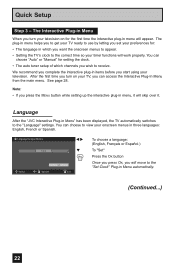
.... You can choose "Auto" or "Manual" for : • The language in which channels you want the onscreen menus to appear. • Setting the TV's clock to receive. Language/Langue/Idioma English Select OK Operate √® † Set MENU Exit To choose a language: (English, Français or...setting up the interactive plug-in menu will skip over it will appear. Language After the "JVC Interactive Plug-in Menu automatically. (Continued...) 22 The plug-in menu helps you to get your TV ready to use by letting you set your preferences for setting the clock. • The auto...
.... You can choose "Auto" or "Manual" for : • The language in which channels you want the onscreen menus to appear. • Setting the TV's clock to receive. Language/Langue/Idioma English Select OK Operate √® † Set MENU Exit To choose a language: (English, Français or...setting up the interactive plug-in menu will skip over it will appear. Language After the "JVC Interactive Plug-in Menu automatically. (Continued...) 22 The plug-in menu helps you to get your TV ready to use by letting you set your preferences for setting the clock. • The auto...
Instructions
Page 23
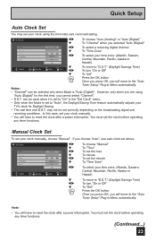
... using the time data sent via broadcasting. However, only when you selected "Auto (Digital)" To select a receiving digital channel To "Time Zone" To select your TV's clock for the first time, you will have to "D.S.T." (Daylight Savings Time) Select Operate Back Exit è To turn "On or Off" To "Set...
... using the time data sent via broadcasting. However, only when you selected "Auto (Digital)" To select a receiving digital channel To "Time Zone" To select your TV's clock for the first time, you will have to "D.S.T." (Daylight Savings Time) Select Operate Back Exit è To turn "On or Off" To "Set...


