
Printer Friendly Spec
Page 2
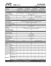
... 3000 HDTV www.jvc.com Model Name JLC32BC3000 JLC37BC3000 JLC42BC3000 JLC47BC3000 Model Title 32" BlackCrystal™, FHD 37" BlackCrystal™, FHD 42" BlackCrystal™, FHD 47" BlackCrystal™, FHD 1080p, 60Hz,LCD TV 1080p, 60Hz, LCD TV 1080p, 120Hz, LCD TV 1080p, 120Hz, LCD TV Panel Size Class...™ , SRS StudioSound HD™ Audio Output Power 20W (10W x 2) Front Firing speakers MTS decode/Graphic Equalizer Yes TV Features Color Enhancement Yes, CrystalColor™ PIP/POP No Yes Picture Mode 6 Picture Mode, plus multiple customizable modes Built-in ...
... 3000 HDTV www.jvc.com Model Name JLC32BC3000 JLC37BC3000 JLC42BC3000 JLC47BC3000 Model Title 32" BlackCrystal™, FHD 37" BlackCrystal™, FHD 42" BlackCrystal™, FHD 47" BlackCrystal™, FHD 1080p, 60Hz,LCD TV 1080p, 60Hz, LCD TV 1080p, 120Hz, LCD TV 1080p, 120Hz, LCD TV Panel Size Class...™ , SRS StudioSound HD™ Audio Output Power 20W (10W x 2) Front Firing speakers MTS decode/Graphic Equalizer Yes TV Features Color Enhancement Yes, CrystalColor™ PIP/POP No Yes Picture Mode 6 Picture Mode, plus multiple customizable modes Built-in ...
User Manual
Page 1
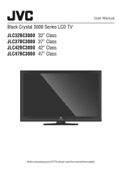
Black Crystal 3000 Series LCD TV JLC32BC3000 32" Class JLC37BC3000 37" Class JLC42BC3000 42" Class JLC47BC3000 47" Class User Manual Before operating your LCD TV, please read this manual thoroughly.
Black Crystal 3000 Series LCD TV JLC32BC3000 32" Class JLC37BC3000 37" Class JLC42BC3000 42" Class JLC47BC3000 47" Class User Manual Before operating your LCD TV, please read this manual thoroughly.

User Manual
Page 2
...and serial number located at our wesite http://go .jvc.com/HDTVSupport/. JVC, THE JVC LOGO, AND OTHER JVC TRADEMARKS ARE THE INTELLECTUAL PROPERTY OF JVC KENWOOD Corporation. We hope that you register your new JVC LCD TV. Retain your JVC LCD TV, read these instructions before making any adjustments, and retain...are trademarks or registered trademarks of HDMI Licensing LLC in the "factory default" setting and this is incorporated under license from your JVC LCD TV either at the back of Serial Number: Model Number: SRS StudioSound HD is a trademark of the manual. THE TRADEMARKS SHOWN ...
...and serial number located at our wesite http://go .jvc.com/HDTVSupport/. JVC, THE JVC LOGO, AND OTHER JVC TRADEMARKS ARE THE INTELLECTUAL PROPERTY OF JVC KENWOOD Corporation. We hope that you register your new JVC LCD TV. Retain your JVC LCD TV, read these instructions before making any adjustments, and retain...are trademarks or registered trademarks of HDMI Licensing LLC in the "factory default" setting and this is incorporated under license from your JVC LCD TV either at the back of Serial Number: Model Number: SRS StudioSound HD is a trademark of the manual. THE TRADEMARKS SHOWN ...

User Manual
Page 3
... ELECTRIC SHOCK. WARNING: TO PREVENT FIRE OR SHOCK HAZARD, DO NOT EXPOSE THIS APPLIANCE TO RAIN OR MOISTURE. Consult the dealer or an experienced radio/TV technician for a Class B digital device, pursuant to provide reasonable protection against harmful interference in this equipment does cause harmful interference to radio or television reception...
... ELECTRIC SHOCK. WARNING: TO PREVENT FIRE OR SHOCK HAZARD, DO NOT EXPOSE THIS APPLIANCE TO RAIN OR MOISTURE. Consult the dealer or an experienced radio/TV technician for a Class B digital device, pursuant to provide reasonable protection against harmful interference in this equipment does cause harmful interference to radio or television reception...
User Manual
Page 5
... instructions when making home entertainment enjoyable and safe. It may cause speaker overheating and fire. 25) This reminder is provided to call the cable TV system installer's attention to making any connections. 23) Sudden high volume sound may cause hearing or speaker damage. Follow the manufacturer's recommendations for... NEC that provides guidelines for the safe installation and use of your purchase! The consumer electronics industry is a growing trend and larger TVs are popular purchases. If you connect the product to do so may cause an electric shock and serious personal injury...
... instructions when making home entertainment enjoyable and safe. It may cause speaker overheating and fire. 25) This reminder is provided to call the cable TV system installer's attention to making any connections. 23) Sudden high volume sound may cause hearing or speaker damage. Follow the manufacturer's recommendations for... NEC that provides guidelines for the safe installation and use of your purchase! The consumer electronics industry is a growing trend and larger TVs are popular purchases. If you connect the product to do so may cause an electric shock and serious personal injury...
User Manual
Page 6
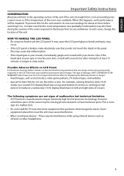
...TO HANDLE THE LCD PANEL • Do not press hard or jolt the LCD panel. Never leave your TV on for at top and bottom of a malfunction. • Do not install the TV near this happens, unit's performance will form in the LCD Panel and cause subtle but technical limitation. &#...8226; LCD Panels are manufactured using infrared devices such as stock tickers, video game patterns, TV station logos, and websites. • Special Formats that do not touch the liquid in its new surroundings for long periods of time, the image...
...TO HANDLE THE LCD PANEL • Do not press hard or jolt the LCD panel. Never leave your TV on for at top and bottom of a malfunction. • Do not install the TV near this happens, unit's performance will form in the LCD Panel and cause subtle but technical limitation. &#...8226; LCD Panels are manufactured using infrared devices such as stock tickers, video game patterns, TV station logos, and websites. • Special Formats that do not touch the liquid in its new surroundings for long periods of time, the image...
User Manual
Page 7
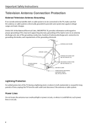
...(NEC SECTION 810-21) GROUND CLAMPS POWER SERVICE GROUNDING ELECTRODE SYSTEM (NEC ART 250, PART H) Lightning Protection For added protection of the TV during a lightning storm or when it could fall into such power lines or circuits. 6 Important Safety Instructions Television Antenna Connection Protection External ...Television Antenna Grounding If an outside antenna/satellite dish or cable system is to be connected to the TV, make sure that the antenna or cable system is left unattended or unused for long periods of the grounding electrode. Power ...
...(NEC SECTION 810-21) GROUND CLAMPS POWER SERVICE GROUNDING ELECTRODE SYSTEM (NEC ART 250, PART H) Lightning Protection For added protection of the TV during a lightning storm or when it could fall into such power lines or circuits. 6 Important Safety Instructions Television Antenna Connection Protection External ...Television Antenna Grounding If an outside antenna/satellite dish or cable system is to be connected to the TV, make sure that the antenna or cable system is left unattended or unused for long periods of the grounding electrode. Power ...
User Manual
Page 8
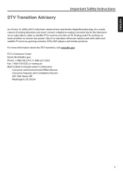
... Division 445 12th Street, SW Washington, DC 20554 7 or writing to receive low power, Class A or translator television stations and with cable and satellite TV services, gaming consoles, VCRs, DVD players, and similar products. FCC's Consumer Center Email: [email protected] Phone: 1-888-CALL-FCC (1-888-225-5322... As of analog television sets must connect a digital-to-analog converter box to the television set or subscribe to cable or satellite TV to receive over-the-air TV. For more information about the DTV transition, visit www.dtv.gov. As a result, owners of June 12, 2009, all ...
... Division 445 12th Street, SW Washington, DC 20554 7 or writing to receive low power, Class A or translator television stations and with cable and satellite TV services, gaming consoles, VCRs, DVD players, and similar products. FCC's Consumer Center Email: [email protected] Phone: 1-888-CALL-FCC (1-888-225-5322... As of analog television sets must connect a digital-to-analog converter box to the television set or subscribe to cable or satellite TV to receive over-the-air TV. For more information about the DTV transition, visit www.dtv.gov. As a result, owners of June 12, 2009, all ...
User Manual
Page 9
Contents Important Safety Instructions 3 Television Antenna Connection Protection.... 6 DTV Transition Advisory 7 Attaching the Stand 10 Unpacking the TV 10 JLC32BC3000 10 JLC37BC3000 & JLC42BC3000 11 JLC47BC3000 11 Removing the Stand 11 Package Contents 12 Remote Control Batteries 12 Parts and ...17 Digital Connection 17 Analog Connection 17 Connecting Computers and Laptops 18 Basic Operations 19 Setup Wizard 19 Exit Retail Mode 20 Basic TV Operation 20 Changing Channel 20 Mute Volume 21 Set Sleep Timer 21 Display Info 21 Set Aspect Ratio 21 Selecting Input Source ...
Contents Important Safety Instructions 3 Television Antenna Connection Protection.... 6 DTV Transition Advisory 7 Attaching the Stand 10 Unpacking the TV 10 JLC32BC3000 10 JLC37BC3000 & JLC42BC3000 11 JLC47BC3000 11 Removing the Stand 11 Package Contents 12 Remote Control Batteries 12 Parts and ...17 Digital Connection 17 Analog Connection 17 Connecting Computers and Laptops 18 Basic Operations 19 Setup Wizard 19 Exit Retail Mode 20 Basic TV Operation 20 Changing Channel 20 Mute Volume 21 Set Sleep Timer 21 Display Info 21 Set Aspect Ratio 21 Selecting Input Source ...
User Manual
Page 11
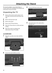
... top foam caps. 3 Remove the stand. 4 Remove the TV from the box. 5 Place the TV face down on model. Perform the installation according to the instructions of your TV model. 3 Connect the base to the stand. 4 Secure the base to the instructions of your TV model. JLC32BC3000 1 Align the rear-side screw holes with the...
... top foam caps. 3 Remove the stand. 4 Remove the TV from the box. 5 Place the TV face down on model. Perform the installation according to the instructions of your TV model. 3 Connect the base to the stand. 4 Secure the base to the instructions of your TV model. JLC32BC3000 1 Align the rear-side screw holes with the...

User Manual
Page 12
To remove the stand, perform the assemble steps in the carton. Attaching the Stand JLC47BC3000 1 Align the bottom four screw holes with the neck and stand, and secure with the provided four screws and screwdriver. 2 Secure the base with the thumbscrew. 3 Attach the neck cover firmly until it locks into place. ENGLISH JLC37BC3000 & JLC42BC3000 1 Connect the base to your TV model. 11 Removing the Stand When the TV needs to be transported, remove the stand and pack the TV back in reverse order according to the stand.
To remove the stand, perform the assemble steps in the carton. Attaching the Stand JLC47BC3000 1 Align the bottom four screw holes with the neck and stand, and secure with the provided four screws and screwdriver. 2 Secure the base with the thumbscrew. 3 Attach the neck cover firmly until it locks into place. ENGLISH JLC37BC3000 & JLC42BC3000 1 Connect the base to your TV model. 11 Removing the Stand When the TV needs to be transported, remove the stand and pack the TV back in reverse order according to the stand.
User Manual
Page 13
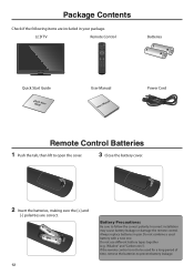
... Incorrect installation may cause battery leakage or damage the remote control. Do not use different battery types together (e.g. Always replace batteries in your package. LCD TV Remote Control I N SLEEP NPUT MENU MEDIA INFO OK W IDE AUDIO RETUR VOL CH MUTE 123 456 789 _ 0 ENT HDMI PC... TV VIDEO COMP MUSIC Batteries Quick Start Guide QGuuicidkeStart User Manual User's Manual Power Cord Remote Control Batteries 1 Push the tab, then lift to open ...
... Incorrect installation may cause battery leakage or damage the remote control. Do not use different battery types together (e.g. Always replace batteries in your package. LCD TV Remote Control I N SLEEP NPUT MENU MEDIA INFO OK W IDE AUDIO RETUR VOL CH MUTE 123 456 789 _ 0 ENT HDMI PC... TV VIDEO COMP MUSIC Batteries Quick Start Guide QGuuicidkeStart User Manual User's Manual Power Cord Remote Control Batteries 1 Push the tab, then lift to open ...
User Manual
Page 14
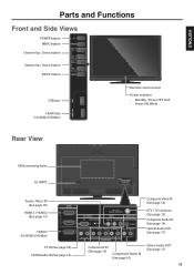
...• Standby / Power OFF: Red • Power ON: White Rear View VESA mounting holes AC INPUT AC IN HDMI 1 2 3 PC / MUSIC PC AUDIO / MUSIC DTV / TV CABLE / ANTENNA VIDEO VIDEO L AUDIO R AUDIO OUT OPTICAL Y Pb/Cb Pr/Cr L AUDIO R L R L AUDIO R COMPONENT Audio / Music IN (See page 18) HDMI 1 ...HDMI 1 2 3 PC IN (See page 18) HDMI Audio IN (See page 14) Composite Video IN (See page 14) PC / MUSIC PC AUDIO / MUSIC DTV / TV CABLE / ANTENNA VIDEO VIDEO L AUDIO R AUDIO OUT OPTICAL Y Pb/Cb Pr/Cr L AUDIO R L R L AUDIO R COMPONENT Component IN (See page 16) Component ...
...• Standby / Power OFF: Red • Power ON: White Rear View VESA mounting holes AC INPUT AC IN HDMI 1 2 3 PC / MUSIC PC AUDIO / MUSIC DTV / TV CABLE / ANTENNA VIDEO VIDEO L AUDIO R AUDIO OUT OPTICAL Y Pb/Cb Pr/Cr L AUDIO R L R L AUDIO R COMPONENT Audio / Music IN (See page 18) HDMI 1 ...HDMI 1 2 3 PC IN (See page 18) HDMI Audio IN (See page 14) Composite Video IN (See page 14) PC / MUSIC PC AUDIO / MUSIC DTV / TV CABLE / ANTENNA VIDEO VIDEO L AUDIO R AUDIO OUT OPTICAL Y Pb/Cb Pr/Cr L AUDIO R L R L AUDIO R COMPONENT Component IN (See page 16) Component ...
User Manual
Page 15
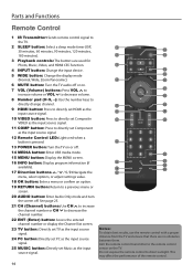
... and HDMI CEC function. 4 INPUT button: Change the input device. 5 WIDE button: Change the display mode (Normal, Wide, Zoom Panoramic). 6 MUTE button: Turn the TV audio off or on. 7 VOL (Volume) buttons: Press VOL to increase volume or VOL to decrease volume. 8 Number pad (0~9, -): Use the number keys to directly...directly set Music as the input source signal. 12 Remote Control LED: Lights red when a button is pressed. 13 POWER button: Turn the TV on the TV. This may affect the performance of the remote control. 14 Do not expose the remote control to decrease the channel number. 22 ENT (...
... and HDMI CEC function. 4 INPUT button: Change the input device. 5 WIDE button: Change the display mode (Normal, Wide, Zoom Panoramic). 6 MUTE button: Turn the TV audio off or on. 7 VOL (Volume) buttons: Press VOL to increase volume or VOL to decrease volume. 8 Number pad (0~9, -): Use the number keys to directly...directly set Music as the input source signal. 12 Remote Control LED: Lights red when a button is pressed. 13 POWER button: Turn the TV on the TV. This may affect the performance of the remote control. 14 Do not expose the remote control to decrease the channel number. 22 ENT (...
User Manual
Page 16
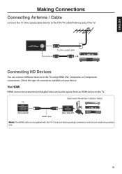
...Connections Connecting Antenna / Cable Connect the 75 ohm coaxial cable directly to the DTV/TV Cable/Antenna jack of connection available on your retailer to purchase one. 15 Game Console / Blu-ray Player / Cable Box / Satellite TV TM HDMI HDMI Video / Audio IN HDMI cable Video / Audio OUT Note: ...The HDMI cable is not supplied with the TV. Check the type of the TV. Via HDMI HDMI connection transmits both digital video and audio signals from ...
...Connections Connecting Antenna / Cable Connect the 75 ohm coaxial cable directly to the DTV/TV Cable/Antenna jack of connection available on your retailer to purchase one. 15 Game Console / Blu-ray Player / Cable Box / Satellite TV TM HDMI HDMI Video / Audio IN HDMI cable Video / Audio OUT Note: ...The HDMI cable is not supplied with the TV. Check the type of the TV. Via HDMI HDMI connection transmits both digital video and audio signals from ...
User Manual
Page 17
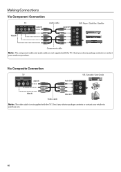
... Video IN Video cable VCR / Camcorder / Game Console Audio OUT Video OUT R AUDIO L VIDEO Note: The video cable is not supplied with the TV. Making Connections Via Component Connection TV Y Pb/Cb Pr/Cr AUDIO L R Audio IN Video IN COMPONENT Audio cable Audio OUT R AUDIO L DVD Player / Cable Box / Satellite Pr/Cr... Pb/Cb Video OUT Y Component cable Note: The component cable and audio cable are not supplied with the TV. Check your device package contents or contact your retailer to purchase.
... Video IN Video cable VCR / Camcorder / Game Console Audio OUT Video OUT R AUDIO L VIDEO Note: The video cable is not supplied with the TV. Making Connections Via Component Connection TV Y Pb/Cb Pr/Cr AUDIO L R Audio IN Video IN COMPONENT Audio cable Audio OUT R AUDIO L DVD Player / Cable Box / Satellite Pr/Cr... Pb/Cb Video OUT Y Component cable Note: The component cable and audio cable are not supplied with the TV. Check your device package contents or contact your retailer to purchase.

User Manual
Page 18
...audio device package contents or contact your retailer to purchase. Analog Connection Connect the RCA audio cable to the Audio OUT L/R port of the TV and the port of the soundbar, AV receiver, or audio system. ENGLISH Making Connections Connecting External Speakers / Soundbar / AV Receivers Digital ...Connection Connect the SPDIF/Optical audio cable to the Audio OUT optical port of the TV and the optical port of the soundbar, AV receiver, or audio system. Digital Audio System TV AUDIO OUT OPTICAL Audio OUT Audio IN OPTICAL Optical audio cable Note: • The optical...
...audio device package contents or contact your retailer to purchase. Analog Connection Connect the RCA audio cable to the Audio OUT L/R port of the TV and the port of the soundbar, AV receiver, or audio system. ENGLISH Making Connections Connecting External Speakers / Soundbar / AV Receivers Digital ...Connection Connect the SPDIF/Optical audio cable to the Audio OUT optical port of the TV and the optical port of the soundbar, AV receiver, or audio system. Digital Audio System TV AUDIO OUT OPTICAL Audio OUT Audio IN OPTICAL Optical audio cable Note: • The optical...
User Manual
Page 19
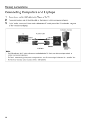
...; The VGA cable and the PC audio cable are not supplied with the TV. Check your device package contents or contact your retailer to the PC audio port of the TV and audio out port of time. • The TV is best viewed at native resolution (1920 x 1080 @ 60Hz). 18 Making Connections Connecting... Computers and Laptops 1 Connect one end of a VGA cable to the PC port of the TV. 2 Connect the other end of the VGA cable to the RGB port of the computer or laptop. 3 For PC audio, connect a 3.5mm audio cable to...
...; The VGA cable and the PC audio cable are not supplied with the TV. Check your device package contents or contact your retailer to the PC audio port of the TV and audio out port of time. • The TV is best viewed at native resolution (1920 x 1080 @ 60Hz). 18 Making Connections Connecting... Computers and Laptops 1 Connect one end of a VGA cable to the PC port of the TV. 2 Connect the other end of the VGA cable to the RGB port of the computer or laptop. 3 For PC audio, connect a 3.5mm audio cable to...

User Manual
Page 20
... start auto scan. Time Zone Select the Time Zone Time Zone: Alaska Change OK Select RETURN Previous Setup INFO Exit 5 Press or to select the TV Mode, then press OK. Change OK Select RETURN Previous Setup INFO Exit 19 Auto Scan Select the Signal Type of your... TV. ENGLISH Basic Operations Setup Wizard When the TV is turned on the TV. TV Mode options are: • Home Mode: Select this mode for in home use. • Retail Mode: Select this mode...
... start auto scan. Time Zone Select the Time Zone Time Zone: Alaska Change OK Select RETURN Previous Setup INFO Exit 5 Press or to select the TV Mode, then press OK. Change OK Select RETURN Previous Setup INFO Exit 19 Auto Scan Select the Signal Type of your... TV. ENGLISH Basic Operations Setup Wizard When the TV is turned on the TV. TV Mode options are: • Home Mode: Select this mode for in home use. • Retail Mode: Select this mode...
User Manual
Page 21
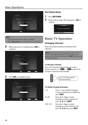
... Changing Channel Press the number buttons to complete setup. Note: After pressing the number buttons, there will be a few seconds delay before the TV changes channel. To Select Analog Channels 1~9 Press 1~9 as needed. OK OK Select RETURN Previous Setup INFO Exit Exit Retail Mode 1 Press RETURN. 2 ... Press the 3 digits in order. To Browse Channel Press the Channel up/down buttons on the remote control or CH , CH on the TV to exit Setup Wizard. Scan Finish Channel scan completed. Example, to stop scanning, please press "Stop Scan".
... Changing Channel Press the number buttons to complete setup. Note: After pressing the number buttons, there will be a few seconds delay before the TV changes channel. To Select Analog Channels 1~9 Press 1~9 as needed. OK OK Select RETURN Previous Setup INFO Exit Exit Retail Mode 1 Press RETURN. 2 ... Press the 3 digits in order. To Browse Channel Press the Channel up/down buttons on the remote control or CH , CH on the TV to exit Setup Wizard. Scan Finish Channel scan completed. Example, to stop scanning, please press "Stop Scan".


