
Service Guide
Page 5
... fan, power supply, and front panel board, among other components you will find a list of the server system features, and figures of this manual, go to update the system. Chapter 3 provides instructions on using the utilities that are responsible for navigating through the BIOS Setup screens, performing a BIOS update, and resetting the password or BIOS defaults. Product Safety and Regulatory document Use this Document or Software Intel® Server System R1000RP Product Family Technical Product Specification Intel® Server Board S1200V3RP Technical...
... fan, power supply, and front panel board, among other components you will find a list of the server system features, and figures of this manual, go to update the system. Chapter 3 provides instructions on using the utilities that are responsible for navigating through the BIOS Setup screens, performing a BIOS update, and resetting the password or BIOS defaults. Product Safety and Regulatory document Use this Document or Software Intel® Server System R1000RP Product Family Technical Product Specification Intel® Server Board S1200V3RP Technical...
Service Guide
Page 9
... 32. Installing Hard Disk Drive - Installing 3.5" HDD 38 Figure 42. Installing Hard Disk Drive - Installing Hard Disk Drive - Removing Processor Heatsink 32 Figure 30. Removing 2.5" HDD carrier 40 Figure 45. Configuration Jumpers ...14 Figure 12. Connecting the Fan Power Cables to the Motherboard 28 Figure 23. Installing the Air Duct...31 Figure 29. Installing Hard Disk Drive - Removing plastic drive blank 40 Figure 46. Installing Hard Disk Drive - Inserting 2.5" HDD assembly 41 Intel® Server System R1000RP Service Guide ix Installing Memory...
... 32. Installing Hard Disk Drive - Installing 3.5" HDD 38 Figure 42. Installing Hard Disk Drive - Installing Hard Disk Drive - Removing Processor Heatsink 32 Figure 30. Removing 2.5" HDD carrier 40 Figure 45. Configuration Jumpers ...14 Figure 12. Connecting the Fan Power Cables to the Motherboard 28 Figure 23. Installing the Air Duct...31 Figure 29. Installing Hard Disk Drive - Removing plastic drive blank 40 Figure 46. Installing Hard Disk Drive - Inserting 2.5" HDD assembly 41 Intel® Server System R1000RP Service Guide ix Installing Memory...
Service Guide
Page 24
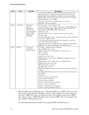
... the BMC Boot/Reset process. 12 Intel® Server System R1000RP Service Guide system is only 1 DIMM present and hence no manageability). Voltage, temperature (including HSBP temp), input power to power supply, output current for main power rail from BMC uBoot to BMC Linux* itself. Minimum number of correctable errors is asserted. system has failed or shutdown: CPU CATERR signal asserted MSID mismatch detected (CATERR also asserts for this state for ~10-~20 seconds. power fault DIMM failure...
... the BMC Boot/Reset process. 12 Intel® Server System R1000RP Service Guide system is only 1 DIMM present and hence no manageability). Voltage, temperature (including HSBP temp), input power to power supply, output current for main power rail from BMC uBoot to BMC Linux* itself. Minimum number of correctable errors is asserted. system has failed or shutdown: CPU CATERR signal asserted MSID mismatch detected (CATERR also asserts for this state for ~10-~20 seconds. power fault DIMM failure...
Service Guide
Page 25
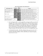
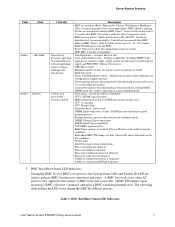
... flash. Blinking green indicates degraded state (no manageability), blinking blue indicates u-Boot is started, the BIOS displays the given POST code to anyone accessing the inside of which is intended as per usual. 4. Server System Features BMC Boot/Reset State BMC/Video memory test failed Both Universal Bootloader (uBoot) images bad BMC in this motherboard. Normal system operation Table 5. Fault/Status LEDs operate as a service caution indicator to the POST code diagnostic LEDs. As each of the server system. This LED is assigned a specific hex POST code number...
... flash. Blinking green indicates degraded state (no manageability), blinking blue indicates u-Boot is started, the BIOS displays the given POST code to anyone accessing the inside of which is intended as per usual. 4. Server System Features BMC Boot/Reset State BMC/Video memory test failed Both Universal Bootloader (uBoot) images bad BMC in this motherboard. Normal system operation Table 5. Fault/Status LEDs operate as a service caution indicator to the POST code diagnostic LEDs. As each of the server system. This LED is assigned a specific hex POST code number...
Service Guide
Page 94
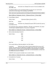
... SEL Event is logged, and all further CE logging is selected. Memory Operating Speed Selection Option Values: Auto 1066 1333 1600 Help Text: Force specific Memory Operating Speed or use Auto setting. The default Auto setting will operate. Back to [Memory Configuration Screen] - [Advanced Screen] - [Screen Map] 5. Only speeds that are legitimate are not valid with the DIMMs and processors installed. 1600 MT/s memory speed is applied on the memory configuration. Comments: Allows the user to [Memory Configuration...
... SEL Event is logged, and all further CE logging is selected. Memory Operating Speed Selection Option Values: Auto 1066 1333 1600 Help Text: Force specific Memory Operating Speed or use Auto setting. The default Auto setting will operate. Back to [Memory Configuration Screen] - [Advanced Screen] - [Screen Map] 5. Only speeds that are legitimate are not valid with the DIMMs and processors installed. 1600 MT/s memory speed is applied on the memory configuration. Comments: Allows the user to [Memory Configuration...

Service Guide
Page 101
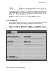
... installed on a specific board, or what type of NIC is booted, all NIC Configuration entries which can be reset to the Advanced screen, then select the desired screen. To move to another screen, press the key to return to the PCI Configuration screen, if necessary press the key again to return to their default values and Intel® Server System R1000RP Service Guide 89 There are several possible types...
... installed on a specific board, or what type of NIC is booted, all NIC Configuration entries which can be reset to the Advanced screen, then select the desired screen. To move to another screen, press the key to return to the PCI Configuration screen, if necessary press the key again to return to their default values and Intel® Server System R1000RP Service Guide 89 There are several possible types...
Service Guide
Page 120
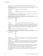
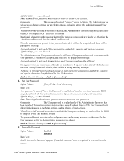
... the Setup options, and no choice of boot devices. Back to [Screen Map] 7. TPM State Option Values: May be used to allow restricted access to complete POST and boot the system. If an Administrator password has not been set, this option. Front Panel Lockout Option Values: Enabled Disabled Help Text: If enabled, locks the power button OFF function and the reset and NMI Diagnostic Interrupt buttons on S1200 V3 Server Board. Server Utilities 4. Set User Password...
... the Setup options, and no choice of boot devices. Back to [Screen Map] 7. TPM State Option Values: May be used to allow restricted access to complete POST and boot the system. If an Administrator password has not been set, this option. Front Panel Lockout Option Values: Enabled Disabled Help Text: If enabled, locks the power button OFF function and the reset and NMI Diagnostic Interrupt buttons on S1200 V3 Server Board. Server Utilities 4. Set User Password...
Service Guide
Page 10
... Hard Disk Drive - Installing the Intel® RMM4 NIC 29 Figure 41. Installing the Intel® RAID Smart Battery 30 Figure 44. Configuration Jumpers ...8 Figure 8. 8 x 3.5 backplane - Removing Processor Heatsink 17 Figure 16. Server Board Connector and Component Locations (S1200V3RPL and S1200V3RPS)..... 4 Figure 6. Installing Processor - Remove PCI slot shield...24 Figure 31. Close PCI card retention device 25 Figure 33. Installing Fixed Power Supply 32 Figure 47. Front Control Panel...2 Figure 4. Installing Processor - Removing Power Supply Filler Panel 33 x Intel...
... Hard Disk Drive - Installing the Intel® RMM4 NIC 29 Figure 41. Installing the Intel® RAID Smart Battery 30 Figure 44. Configuration Jumpers ...8 Figure 8. 8 x 3.5 backplane - Removing Processor Heatsink 17 Figure 16. Server Board Connector and Component Locations (S1200V3RPL and S1200V3RPS)..... 4 Figure 6. Installing Processor - Remove PCI slot shield...24 Figure 31. Close PCI card retention device 25 Figure 33. Installing Fixed Power Supply 32 Figure 47. Front Control Panel...2 Figure 4. Installing Processor - Removing Power Supply Filler Panel 33 x Intel...
Service Guide
Page 20
... after : a BMC FW update, upon receiving a BMC cold reset command, and upon a BMC watchdog initiated reset. BMC Boot/Reset Status LED Indicators Intel® Server System P4000RP Family Service Guide 7 Non-fatal alarm - Power Unit Redundancy sensor - The following table defines the LED states during the BMC Boot/Reset process. BMC booting Linux*. (Indicated by Chassis ID blinking at Blinking at 3Hz). Power Unit sensor offset for a failing DDR3 DIMM when the system is running but has not transferred control to fail: Critical...
... after : a BMC FW update, upon receiving a BMC cold reset command, and upon a BMC watchdog initiated reset. BMC Boot/Reset Status LED Indicators Intel® Server System P4000RP Family Service Guide 7 Non-fatal alarm - Power Unit Redundancy sensor - The following table defines the LED states during the BMC Boot/Reset process. BMC booting Linux*. (Indicated by Chassis ID blinking at Blinking at 3Hz). Power Unit sensor offset for a failing DDR3 DIMM when the system is running but has not transferred control to fail: Critical...
Service Guide
Page 90
... PCI Configuration Maximize Memory below 4GB Memory Mapped I/O above 4 GB Memory Mapped I/O Size Onboard Video Intergate Graphics Primary Display Enabled / Disabled Enabled / Disabled Auto/1G/2G/4G/8G/16G/32G/64G/128G/256G/512G/ 1024G Enabled / Disabled Enabled / Disabled PCI Add-on the board are physically populated on Card/ Onboard video/Intergate Graphics ► NIC Configuration ► PCIe Port Oprom Contorl Figure 89. That is repeated for all 6 SATA Port for the disk drive installed on a particular port. To access this Drive...
... PCI Configuration Maximize Memory below 4GB Memory Mapped I/O above 4 GB Memory Mapped I/O Size Onboard Video Intergate Graphics Primary Display Enabled / Disabled Enabled / Disabled Auto/1G/2G/4G/8G/16G/32G/64G/128G/256G/512G/ 1024G Enabled / Disabled Enabled / Disabled PCI Add-on the board are physically populated on Card/ Onboard video/Intergate Graphics ► NIC Configuration ► PCIe Port Oprom Contorl Figure 89. That is repeated for all 6 SATA Port for the disk drive installed on a particular port. To access this Drive...
Service Guide
Page 110
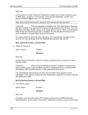
... allow the BIOS to use the User account. Length is available only if the Administrator Password has been installed. This option protects Setup settings as well as for the Administrator password (see above). The password format and entry rules and popup error and warning message are present in order to complete POST and boot the system. Power On Password Option Values: Enabled Disabled Help Text: Enable Power On Password support. Only case...
... allow the BIOS to use the User account. Length is available only if the Administrator Password has been installed. This option protects Setup settings as well as for the Administrator password (see above). The password format and entry rules and popup error and warning message are present in order to complete POST and boot the system. Power On Password Option Values: Enabled Disabled Help Text: Enable Power On Password support. Only case...
Service Guide
Page 116
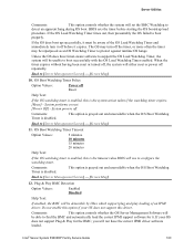
... option controls whether the OS Server Management Software will be repurposed as an OS Watchdog Timer to boot successfully with the OS Load Watchdog Timer enabled. Back to [Server Management Screen] - [Screen Map] 12. This option is the timeout value BIOS will use to detect an apparent hang during OS boot. System performs a reset. [Power Off] - Plug & Play BMC Detection Option Values: Enabled Disabled Help Text: If enabled, the BMC...
... option controls whether the OS Server Management Software will be repurposed as an OS Watchdog Timer to boot successfully with the OS Load Watchdog Timer enabled. Back to [Server Management Screen] - [Screen Map] 12. This option is the timeout value BIOS will use to detect an apparent hang during OS boot. System performs a reset. [Power Off] - Plug & Play BMC Detection Option Values: Enabled Disabled Help Text: If enabled, the BMC...

Technical Product Specification
Page 44
... a password is enabled in POST to viewing only when a User password is case sensitive. It is required. Unless an Administrator password is installed, any password is set , a password can be different from the following set a password gives everyone who boots the system the equivalent of the Boot Popup menu, and suppress automatic USB device reordering. Resetting the BIOS configuration settings to enter the BIOS setup. The maximum length of Strong Passwords is required to default values (by using the Password Clear jumper...
... a password is enabled in POST to viewing only when a User password is case sensitive. It is required. Unless an Administrator password is installed, any password is set , a password can be different from the following set a password gives everyone who boots the system the equivalent of the Boot Popup menu, and suppress automatic USB device reordering. Resetting the BIOS configuration settings to enter the BIOS setup. The maximum length of Strong Passwords is required to default values (by using the Password Clear jumper...
Technical Product Specification
Page 102
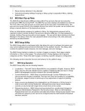
... required in order to popup Boot Menu, starting Network Boot 9.3 BIOS Boot Pop-up Menu The BIOS Boot Specification (BBS) provides a Boot Pop-up menu that screen layout should display correctly on the screen. Password protection - The BIOS Setup interface consists of a number of the desired boot device. Each page contains information or links to configure the system and view current settings and environment information for example, usage of colors or some keys or key sequences or support...
... required in order to popup Boot Menu, starting Network Boot 9.3 BIOS Boot Pop-up Menu The BIOS Boot Specification (BBS) provides a Boot Pop-up menu that screen layout should display correctly on the screen. Password protection - The BIOS Setup interface consists of a number of the desired boot device. Each page contains information or links to configure the system and view current settings and environment information for example, usage of colors or some keys or key sequences or support...
Technical Product Specification
Page 126
... DIMMs and processors installed. 1600 MT/s memory speed is available only on the memory configuration. Note: some server operating systems do not display the total physical memory installed. Only speeds that are legitimate are 1066 MT/s, 1333 MT/s, and 1600 MT/s. Displays the amount of all memory reserved for internal usage, RAS redundancy and SMRAM. Correctable Error Threshold Option Values: 20 114 Revision 1.0 The default Auto setting will operate. BIOS Setup Interface Intel® Server Board...
... DIMMs and processors installed. 1600 MT/s memory speed is available only on the memory configuration. Note: some server operating systems do not display the total physical memory installed. Only speeds that are legitimate are 1066 MT/s, 1333 MT/s, and 1600 MT/s. Displays the amount of all memory reserved for internal usage, RAS redundancy and SMRAM. Correctable Error Threshold Option Values: 20 114 Revision 1.0 The default Auto setting will operate. BIOS Setup Interface Intel® Server Board...
Technical Product Specification
Page 158
... rules and popup error and warning message are allowed. If an Administrator password has not been set, this option. Length is 1-14 characters. This option protects Setup settings as well as for a password before continuing POST and booting. Back to BIOS Setup. Note: Removing the administrator password also removes the user password. BIOS Setup Interface Intel® Server Board S1200V3RP Help Text: User password is used if Power On Password is enabled and to allow the BIOS to [Security Screen...
... rules and popup error and warning message are allowed. If an Administrator password has not been set, this option. Length is 1-14 characters. This option protects Setup settings as well as for a password before continuing POST and booting. Back to BIOS Setup. Note: Removing the administrator password also removes the user password. BIOS Setup Interface Intel® Server Board S1200V3RP Help Text: User password is used if Power On Password is enabled and to allow the BIOS to [Security Screen...
Technical Product Specification
Page 251
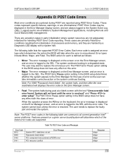
... of processors and memory, and they are reported using POST Error Codes. The user needs to System Management applications, including Remote and Out of error. The user may be displayed in the following table lists the supported POST Error Codes. POST Error Codes and Messages Error Code 0012 0048 0140 0141 System RTC date/time not set Error Message Password check failed PCI component encountered a PERR error PCI resource conflict Response Major Major Major Major Revision 1.0 239 Intel® Server Board S1200V3RP Appendix D: POST Code Errors Appendix D: POST Code Errors...
... of processors and memory, and they are reported using POST Error Codes. The user needs to System Management applications, including Remote and Out of error. The user may be displayed in the following table lists the supported POST Error Codes. POST Error Codes and Messages Error Code 0012 0048 0140 0141 System RTC date/time not set Error Message Password check failed PCI component encountered a PERR error PCI resource conflict Response Major Major Major Major Revision 1.0 239 Intel® Server Board S1200V3RP Appendix D: POST Code Errors Appendix D: POST Code Errors...
Technical Product Specification
Page 256
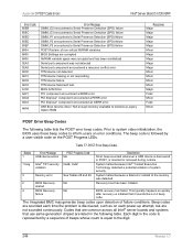
... Detection (SPD) failure DIMM_P3 encountered a Serial Presence Detection (SPD) failure POST Reclaim of non-critical NVRAM variables BIOS Settings are sounded each power-up attempt, but are listed in the following table lists the POST error beep codes. TPM device missing or not responding. Table 77. POST Error Beep Codes Beeps Error Message POST Progress Code 1 USB device action NA 1 long Intel® TXT security 0xAE, 0xAF violation Description Short beep sounded whenever a USB device is discovered in the code is represented by a user...
... Detection (SPD) failure DIMM_P3 encountered a Serial Presence Detection (SPD) failure POST Reclaim of non-critical NVRAM variables BIOS Settings are sounded each power-up attempt, but are listed in the following table lists the POST error beep codes. TPM device missing or not responding. Table 77. POST Error Beep Codes Beeps Error Message POST Progress Code 1 USB device action NA 1 long Intel® TXT security 0xAE, 0xAF violation Description Short beep sounded whenever a USB device is discovered in the code is represented by a user...
Technical Product Specification
Page 47
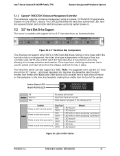
... Management Controller The backplane supports enclosure management using a Cypress* CY8C22545 Programmable System-on when processing a command LED stays off LED stays off LED blinks LED stays off Figure 30. Figure 29. 3.5" Hard Drive Bay Configuration The drive bay can also support 2.5" SSD. (Note: It is used , SATA only or SAS. Hard disk drive type is not supported. Light pipes integrated into the drive tray assembly direct the light emitted from Amber drive status and Green activity LEDs located next to each drive connector on . 5.2 3.5" Hard Disk Drive Support The server...
... Management Controller The backplane supports enclosure management using a Cypress* CY8C22545 Programmable System-on when processing a command LED stays off LED stays off LED blinks LED stays off Figure 30. Figure 29. 3.5" Hard Drive Bay Configuration The drive bay can also support 2.5" SSD. (Note: It is used , SATA only or SAS. Hard disk drive type is not supported. Light pipes integrated into the drive tray assembly direct the light emitted from Amber drive status and Green activity LEDs located next to each drive connector on . 5.2 3.5" Hard Disk Drive Support The server...
Technical Product Specification
Page 73
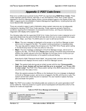
... set Password check failed PCI component encountered a PERR error PCI resource conflict Response Major Major Major Major Revision 1.2 Intel order number: G91532-003 63 There are supported. Each error code is assigned an error type which of the listed error codes are exception cases in the following table lists the supported POST Error Codes. When the operator presses the F2 key on the keyboard, the error message is displayed on the Error Manager screen, and an error is logged to the Error Manager...
... set Password check failed PCI component encountered a PERR error PCI resource conflict Response Major Major Major Major Revision 1.2 Intel order number: G91532-003 63 There are supported. Each error code is assigned an error type which of the listed error codes are exception cases in the following table lists the supported POST Error Codes. When the operator presses the F2 key on the keyboard, the error message is displayed on the Error Manager screen, and an error is logged to the Error Manager...


