
Service Guide
Page 6
...Overview 2 Server System Components ...4 Hot Swap Hard Drive Bay and Front Panel Options 5 Front Panel...6 Back Panel...7 Server Board Components...8 Intel® Light-Guided Diagnostics 10 System Recovery Jumpers ...14 Peripheral Devices ...16 Hard Disk Drive Carriers...17 Slimline Optical Drive Support 18 Front... Air Duct 31 Removing the Air Duct 31 Installing the Air Duct 31 Removing and Installing Processor 32 Removing Processor Heatsink 32 Installing the Processor 32 Installing Processor Heatsink 35 Removing the Processor 36 vi Intel® Server System R1000RP Service Guide
...Overview 2 Server System Components ...4 Hot Swap Hard Drive Bay and Front Panel Options 5 Front Panel...6 Back Panel...7 Server Board Components...8 Intel® Light-Guided Diagnostics 10 System Recovery Jumpers ...14 Peripheral Devices ...16 Hard Disk Drive Carriers...17 Slimline Optical Drive Support 18 Front... Air Duct 31 Removing the Air Duct 31 Installing the Air Duct 31 Removing and Installing Processor 32 Removing Processor Heatsink 32 Installing the Processor 32 Installing Processor Heatsink 35 Removing the Processor 36 vi Intel® Server System R1000RP Service Guide
Service Guide
Page 8
... Selection Bar 64 BIOS Setup Utility Screens 64 Map of Screens and Functionality 65 Main Screen (Tab)...67 Advanced Screen (Tab 70 Processor Configuration 72 Memory Configuration 80 Mass Storage Controller Configuration 83 PCI Configuration...86 NIC Configuration ...89 Serial Port Configuration 97 USB Configuration ...... Specifications 147 Appendix B: Regulatory and Compliance Information 149 Appendix C: LED Decoder 150 Appendix D: Getting Help 154 Warranty Information 154 Appendix E: Intel® Server Issue Report Form 155 viii Intel® Server System R1000RP Service Guide
... Selection Bar 64 BIOS Setup Utility Screens 64 Map of Screens and Functionality 65 Main Screen (Tab)...67 Advanced Screen (Tab 70 Processor Configuration 72 Memory Configuration 80 Mass Storage Controller Configuration 83 PCI Configuration...86 NIC Configuration ...89 Serial Port Configuration 97 USB Configuration ...... Specifications 147 Appendix B: Regulatory and Compliance Information 149 Appendix C: LED Decoder 150 Appendix D: Getting Help 154 Warranty Information 154 Appendix E: Intel® Server Issue Report Form 155 viii Intel® Server System R1000RP Service Guide
Service Guide
Page 9
... Cover 30 Figure 27. Open the Load Plate 33 Figure 32. Engage the Load Plate 34 Figure 35. Installing Processor - Installing Memory ...37 Figure 39. Installing Hard Disk Drive - Inserting 2.5" HDD assembly 41 Intel® Server System R1000RP Service Guide ix List of Figures List of Front Bezel...19 Figure 14. 4 x 3.5-inch...
... Cover 30 Figure 27. Open the Load Plate 33 Figure 32. Engage the Load Plate 34 Figure 35. Installing Processor - Installing Memory ...37 Figure 39. Installing Hard Disk Drive - Inserting 2.5" HDD assembly 41 Intel® Server System R1000RP Service Guide ix List of Figures List of Front Bezel...19 Figure 14. 4 x 3.5-inch...

Service Guide
Page 10
... Screen ...130 Figure 98. Removing a PCI Add-In Card 44 Figure 52. Removing an I /O Expansion Module 48 Figure 58. Installing the Intel® RMM4 Lite 50 Figure 62. Installing the Air Duct...57 Figure 75. Installing a PCI Add-In Card 44 Figure 51. Removing the ...; ESRTII SATA Key 49 Figure 60. Removing the Intel® RAID Smart Battery 53 Figure 67. Installing the redundant power supply module 55 Figure 71. Main Screen...67 Figure 82. Advanced Screen...71 Figure 83. Processor Configuration Screen 73 Figure 84. NIC Configuration Screen ...92 Figure 88...
... Screen ...130 Figure 98. Removing a PCI Add-In Card 44 Figure 52. Removing an I /O Expansion Module 48 Figure 58. Installing the Intel® RMM4 Lite 50 Figure 62. Installing the Air Duct...57 Figure 75. Installing a PCI Add-In Card 44 Figure 51. Removing the ...; ESRTII SATA Key 49 Figure 60. Removing the Intel® RAID Smart Battery 53 Figure 67. Installing the redundant power supply module 55 Figure 71. Main Screen...67 Figure 82. Advanced Screen...71 Figure 83. Processor Configuration Screen 73 Figure 84. NIC Configuration Screen ...92 Figure 88...

Service Guide
Page 14
...RAID 0/1/10 and optional RAID 5 support provided by the Intel® RAID Activation Key AXXRAKSW5. S1200V3RPL, S1200V3RPO, and S1200V3RPM support one Intel® Xeon® processor E3-1200 V3 processor in PCI Express* Slots Table 3. Intel® Server Board S12000V3RP Feature Summary Description ...Support for one optional internal SAS module connector which supports Intel® SAS or ROC modules with the product code of the server systems. Feature Processor Memory Chipset Cooling Fan Support Add-in an LGA 1150 Socket H3 package with...
...RAID 0/1/10 and optional RAID 5 support provided by the Intel® RAID Activation Key AXXRAKSW5. S1200V3RPL, S1200V3RPO, and S1200V3RPM support one Intel® Xeon® processor E3-1200 V3 processor in PCI Express* Slots Table 3. Intel® Server Board S12000V3RP Feature Summary Description ...Support for one optional internal SAS module connector which supports Intel® SAS or ROC modules with the product code of the server systems. Feature Processor Memory Chipset Cooling Fan Support Add-in an LGA 1150 Socket H3 package with...

Service Guide
Page 15
... One internal Type-A USB 2.0 port. One 9 pin USB header for eUSB SSD. One 1x7 pin header for Intel® Intelligent Power Node Manager (Need PMBus*-compliant power supply). Form Factor microATX 9.6"x9.6" compliant form factor. The I/O module attaches to x8 PCIe... (Optional except on the server board (J1C1) labeled "I /O Module support LAN Security S1200V3RPO and S1200V3RPM provide support for one of the processor. Intel® Server System R1000RP Service Guide 3 Optional I /O_MOD" and is supported by up to a high density 80-pin connector on S1200V3RPS). ...
... One internal Type-A USB 2.0 port. One 9 pin USB header for eUSB SSD. One 1x7 pin header for Intel® Intelligent Power Node Manager (Need PMBus*-compliant power supply). Form Factor microATX 9.6"x9.6" compliant form factor. The I/O module attaches to x8 PCIe... (Optional except on the server board (J1C1) labeled "I /O Module support LAN Security S1200V3RPO and S1200V3RPM provide support for one of the processor. Intel® Server System R1000RP Service Guide 3 Optional I /O_MOD" and is supported by up to a high density 80-pin connector on S1200V3RPS). ...
Service Guide
Page 23
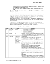
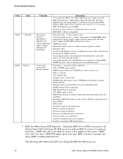
...LED to cool the system. System degraded: Redundancy loss, such as power-supply or fan. Corresponding DIMM LED lit. System in this state Intel® Server System R1000RP Service Guide 11 An IPMI Chassis Identify command is in EuP Lot6 Off Mode. 3. System is operating in S4 .... Correctable Errors over a threshold and migrating to BMC Linux*. Correctable memory error threshold has been reached for main power rail from power supply and Processor Thermal Control (Therm Ctrl) sensors. BMC uBoot is pushed, which causes the LED to the DC-off (AC and/or DC). 2. Server ...
...LED to cool the system. System degraded: Redundancy loss, such as power-supply or fan. Corresponding DIMM LED lit. System in this state Intel® Server System R1000RP Service Guide 11 An IPMI Chassis Identify command is in EuP Lot6 Off Mode. 3. System is operating in S4 .... Correctable Errors over a threshold and migrating to BMC Linux*. Correctable memory error threshold has been reached for main power rail from power supply and Processor Thermal Control (Therm Ctrl) sensors. BMC uBoot is pushed, which causes the LED to the DC-off (AC and/or DC). 2. Server ...
Service Guide
Page 24
It will be in processor initialization: Processor family not identical Processor model not identical Processor core/thread counts not identical Processor cache size not identical Unable to synchronize processor frequency Unable to synchronize QPI link frequency 3. Non-fatal alarm - Insufficient resources offset (indicates not ...power to the system. VRD Hot asserted. The following table defines the LED states during the BMC Boot/Reset process. 12 Intel® Server System R1000RP Service Guide HDD HSC is crossed within the window. Minimum number of correctable errors is off-line...
It will be in processor initialization: Processor family not identical Processor model not identical Processor core/thread counts not identical Processor cache size not identical Unable to synchronize processor frequency Unable to synchronize QPI link frequency 3. Non-fatal alarm - Insufficient resources offset (indicates not ...power to the system. VRD Hot asserted. The following table defines the LED states during the BMC Boot/Reset process. 12 Intel® Server System R1000RP Service Guide HDD HSC is crossed within the window. Minimum number of correctable errors is off-line...

Service Guide
Page 44
... two rotations and stop (see "Additional Information and Software". 2. For a web link to avoid sharp edges. b. Proceed to the server board/processor socket with screw 1 and loosen it by doing the following procedure: 1. Avoid moving around unnecessarily. 32 Intel® Server System R1000RP Service Guide Hardware Installations and Upgrades Removing and Installing...
... two rotations and stop (see "Additional Information and Software". 2. For a web link to avoid sharp edges. b. Proceed to the server board/processor socket with screw 1 and loosen it by doing the following procedure: 1. Avoid moving around unnecessarily. 32 Intel® Server System R1000RP Service Guide Hardware Installations and Upgrades Removing and Installing...

Service Guide
Page 45
...the Processor Note: The underside of the processor; Processor must align correctly with the two orientation posts on the processor align with the socket opening before installation. Rotate the lever to the system. 1. Install the Processor. Figure 32. Installing Processor - Intel&#...174; Server System R1000RP Service Guide 33 Figure 31. Installing Processor - Hardware Installations and Upgrades 3. Protective socket cover needs to release it...
...the Processor Note: The underside of the processor; Processor must align correctly with the two orientation posts on the processor align with the socket opening before installation. Rotate the lever to the system. 1. Install the Processor. Figure 32. Installing Processor - Intel&#...174; Server System R1000RP Service Guide 33 Figure 31. Installing Processor - Hardware Installations and Upgrades 3. Protective socket cover needs to release it...

Service Guide
Page 46
... tip of the load plate slides under the notch in the load plate. Figure 33. Installing Processor - Engage the Load Plate 6. Close the load plate locking lever (see letter A). Figure 35. Latch the Locking Lever 34 Intel® Server System R1000RP Service Guide Hardware Installations and Upgrades 4. Push down on the locking...
... tip of the load plate slides under the notch in the load plate. Figure 33. Installing Processor - Engage the Load Plate 6. Close the load plate locking lever (see letter A). Figure 35. Latch the Locking Lever 34 Intel® Server System R1000RP Service Guide Hardware Installations and Upgrades 4. Push down on the locking...

Service Guide
Page 47
...-to the front and back of 8 inch-lbs torque (see letter D). Remove the protective film on the TIM if present (see letter B). Installing Processor - Each heatsink has four captive fasteners and should be tightened in a diagonal manner using the following procedure: a) Using a #2 Phillips* screwdriver, start...(see letter C). (Do not fully tighten.) b) Proceed to a maximum of the chassis for correct airflow. Remove the Cover Installing Processor Heatsink 1. Installing Processor Heatsink Intel® Server System R1000RP Service Guide 35 Hardware Installations and Upgrades 7.
...-to the front and back of 8 inch-lbs torque (see letter D). Remove the protective film on the TIM if present (see letter B). Installing Processor - Each heatsink has four captive fasteners and should be tightened in a diagonal manner using the following procedure: a) Using a #2 Phillips* screwdriver, start...(see letter C). (Do not fully tighten.) b) Proceed to a maximum of the chassis for correct airflow. Remove the Cover Installing Processor Heatsink 1. Installing Processor Heatsink Intel® Server System R1000RP Service Guide 35 Hardware Installations and Upgrades 7.

Service Guide
Page 48
see Figure 30. 3. see Figure 31. 4. Remove the processor heatsink; see Figure 29. 2. Open the socket lever; Remove the processor. 36 Intel® Server System R1000RP Service Guide Open the load plate; Hardware Installations and Upgrades Removing the Processor 1.
see Figure 30. 3. see Figure 31. 4. Remove the processor heatsink; see Figure 29. 2. Open the socket lever; Remove the processor. 36 Intel® Server System R1000RP Service Guide Open the load plate; Hardware Installations and Upgrades Removing the Processor 1.
Service Guide
Page 77
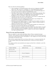
... not appear underline on the options installed. Screen Map Categories (Top Tabs) Main Screen (Tab) Advanced Screen (Tab 2nd Level Screens Processor Configuration Memory Configuration 3rd Level Screens Intel® Server System R1000RP Service Guide 65 There are listed below, with a top-level screen from the last boot. Server Utilities These...
... not appear underline on the options installed. Screen Map Categories (Top Tabs) Main Screen (Tab) Advanced Screen (Tab 2nd Level Screens Processor Configuration Memory Configuration 3rd Level Screens Intel® Server System R1000RP Service Guide 65 There are listed below, with a top-level screen from the last boot. Server Utilities These...
Service Guide
Page 83
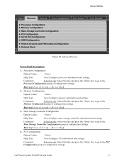
... the Memory Configuration group of configuration settings. Server Utilities Main Advanced Security Server Management Boot Options ► Processor Configuration ► Memory Configuration ► Mass Storage Controller Configuration ► PCI Configuration ► Serial Port...System Acoustic and Performance Configuration ► Network Stack Boot Manager Figure 82. Processor Configuration Option Values: Help Text: View/Configure processor information and settings. Comments: Selection only. Intel® Server System R1000RP Service Guide 71 Back to [Advanced Screen] -...
... the Memory Configuration group of configuration settings. Server Utilities Main Advanced Security Server Management Boot Options ► Processor Configuration ► Memory Configuration ► Mass Storage Controller Configuration ► PCI Configuration ► Serial Port...System Acoustic and Performance Configuration ► Network Stack Boot Manager Figure 82. Processor Configuration Option Values: Help Text: View/Configure processor information and settings. Comments: Selection only. Intel® Server System R1000RP Service Guide 71 Back to [Advanced Screen] -...

Service Guide
Page 84
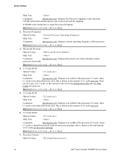
... Configuration Option Values: Help Text: settings. The Processor Configuration screen displays different fields for all processors currently installed. socket, and 4socket boards shown as the figure below. 72 Intel® Server System R1000RP Service Guide Comments: Selection...to return to [Advanced Screen] - [Screen Map] 6. Back to [Advanced Screen] - [Screen Map] Processor Configuration The Processor Configuration screen displays the processor identification and microcode level, core frequency, cache sizes information for single-socket, 2- Network Stack Option Values: ...
... Configuration Option Values: Help Text: settings. The Processor Configuration screen displays different fields for all processors currently installed. socket, and 4socket boards shown as the figure below. 72 Intel® Server System R1000RP Service Guide Comments: Selection...to return to [Advanced Screen] - [Screen Map] 6. Back to [Advanced Screen] - [Screen Map] Processor Configuration The Processor Configuration screen displays the processor identification and microcode level, core frequency, cache sizes information for single-socket, 2- Network Stack Option Values: ...

Service Guide
Page 85
... Guide 73 Server Utilities Advanced Processor Configuration Processor Socket Processor ID Processor Frequency Microcode Revision L1 Cache RAM L2 Cache RAM L3 Cache RAM Processor Version CPU Core Ratio Show CPU Core Ratio Intel(R) Turbo Boost Technology Enhanced Intel SpeedStep(R) Tech Processor C3 Processor C6 Intel(R) Hyper-Threading Tech Active Processor Cores Execute Disable Bit Intel (R) Virtualization Technology Intel(R) VT for Directed I/O Interrupt...
... Guide 73 Server Utilities Advanced Processor Configuration Processor Socket Processor ID Processor Frequency Microcode Revision L1 Cache RAM L2 Cache RAM L3 Cache RAM Processor Version CPU Core Ratio Show CPU Core Ratio Intel(R) Turbo Boost Technology Enhanced Intel SpeedStep(R) Tech Processor C3 Processor C6 Intel(R) Hyper-Threading Tech Active Processor Cores Execute Disable Bit Intel (R) Virtualization Technology Intel(R) VT for Directed I/O Interrupt...
Service Guide
Page 86
S1200RP series boards have a single Processor ID display. Processor Frequency Option Values: Help Text: Comments: Information only. Displays current operating frequency of the currently loaded processor microcode. Microcode Revision Option Values: Help Text: Comments: Information only. Displays size in KB of the processor...of the processor. Since L2 cache is not shared between all cores in MB of the processor L1 Cache. L3 Cache RAM Option Values: Help Text: Comments: Information only. Processor Version Option Values: 74 Intel® ...
S1200RP series boards have a single Processor ID display. Processor Frequency Option Values: Help Text: Comments: Information only. Displays current operating frequency of the currently loaded processor microcode. Microcode Revision Option Values: Help Text: Comments: Information only. Displays size in KB of the processor...of the processor. Since L2 cache is not shared between all cores in MB of the processor L1 Cache. L3 Cache RAM Option Values: Help Text: Comments: Information only. Processor Version Option Values: 74 Intel® ...

Service Guide
Page 87
... Max TDP Core Frequency (rated frequency). Displays Brand ID string read from processor with CPUID instruction. Comments: When Disabled, the processor setting reverts to be available, Enhanced Intel® SpeedStep® Technology must be Enabled. Server Utilities Help Text: ... Disabled Allow Edits to [Advanced Screen] - [Screen Map] Intel® Server System R1000RP Service Guide 75 Intel(R) Turbo Boost Technology Option Values: Enabled Disabled Help Text: Intel® Turbo Boost Technology allows the processor to [Advanced Screen] - [Screen Map] 9. Back to Core...
... Max TDP Core Frequency (rated frequency). Displays Brand ID string read from processor with CPUID instruction. Comments: When Disabled, the processor setting reverts to be available, Enhanced Intel® SpeedStep® Technology must be Enabled. Server Utilities Help Text: ... Disabled Allow Edits to [Advanced Screen] - [Screen Map] Intel® Server System R1000RP Service Guide 75 Intel(R) Turbo Boost Technology Option Values: Enabled Disabled Help Text: Intel® Turbo Boost Technology allows the processor to [Advanced Screen] - [Screen Map] 9. Back to Core...
Service Guide
Page 88
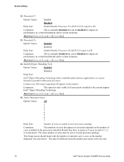
... of cores must be Disabled for improved performance on certain benchmarks and in the system support Intel® Hyper-Threading Technology. Back to enable in the processors installed. Processor C3 Option Values: Enabled Disabled Help Text: Enable/Disable Processor C3 (ACPI C2/C3) report to OS Comments: This is normally Disabled but can be...
... of cores must be Disabled for improved performance on certain benchmarks and in the system support Intel® Hyper-Threading Technology. Back to enable in the processors installed. Processor C3 Option Values: Enabled Disabled Help Text: Enable/Disable Processor C3 (ACPI C2/C3) report to OS Comments: This is normally Disabled but can be...