
Service Guide
Page 5
... System R1000RP Product Family Technical Product Specification Intel® Server Board S1200V3RP Technical Product Specification Intel® Server System R1000RP Product Family Quick Installation Guide Spares and Accessories List and Configuration Guide Intel® Server Configurator tool http://serverconfigurator.intel.com/sct_app.aspx#/SctMain Power Budget Tool Intel® Server Deployment & Management DVD Intel Server Products - Product Safety and Regulatory...
... System R1000RP Product Family Technical Product Specification Intel® Server Board S1200V3RP Technical Product Specification Intel® Server System R1000RP Product Family Quick Installation Guide Spares and Accessories List and Configuration Guide Intel® Server Configurator tool http://serverconfigurator.intel.com/sct_app.aspx#/SctMain Power Budget Tool Intel® Server Deployment & Management DVD Intel Server Products - Product Safety and Regulatory...
Service Guide
Page 8
... 65 Main Screen (Tab)...67 Advanced Screen (Tab 70 Processor Configuration 72 Memory Configuration 80 Mass Storage Controller Configuration 83 PCI Configuration...86 NIC Configuration ...89 Serial Port Configuration 97 USB Configuration ...98 System Acoustic and Performance Configuration 102 Network Stack (Tab 105 Security Screen (Tab 106 Server ...B: Regulatory and Compliance Information 149 Appendix C: LED Decoder 150 Appendix D: Getting Help 154 Warranty Information 154 Appendix E: Intel® Server Issue Report Form 155 viii Intel® Server System R1000RP Service Guide
... 65 Main Screen (Tab)...67 Advanced Screen (Tab 70 Processor Configuration 72 Memory Configuration 80 Mass Storage Controller Configuration 83 PCI Configuration...86 NIC Configuration ...89 Serial Port Configuration 97 USB Configuration ...98 System Acoustic and Performance Configuration 102 Network Stack (Tab 105 Security Screen (Tab 106 Server ...B: Regulatory and Compliance Information 149 Appendix C: LED Decoder 150 Appendix D: Getting Help 154 Warranty Information 154 Appendix E: Intel® Server Issue Report Form 155 viii Intel® Server System R1000RP Service Guide
Service Guide
Page 9
Front Panel Options ...6 Figure 7. Intel® Light-Guided Diagnostic LEDs - Configuration Jumpers ...14 Figure 12. Removing the Front Bezel...29 Figure 24. Installing the System Cover 30 Figure 27. Installing Hard Disk Drive - Installing Hard Disk ...
Front Panel Options ...6 Figure 7. Intel® Light-Guided Diagnostic LEDs - Configuration Jumpers ...14 Figure 12. Removing the Front Bezel...29 Figure 24. Installing the System Cover 30 Figure 27. Installing Hard Disk Drive - Installing Hard Disk ...

Service Guide
Page 10
...75. Removing the Rack Handle 62 Figure 81. Mass Storage Controller Configuration Screen 84 Figure 86. BMC LAN Configuration Screen 121 Figure 97. Removing the Intel® RMM4 Lite 52 Figure 64. Installing the Intel® RAID Smart Battery 53 Figure 66. Installing the Rack ... 67. Installing the Plastic Guide to the Optical Drive 46 Figure 55. Installing the Intel® ESRTII SATA Key 49 Figure 60. Removing the Intel®ESRTII SATA Key 49 Figure 61. Installing the backplane ...61 Figure 79. PCI Configuration Screen...87 Figure 87. Removing...
...75. Removing the Rack Handle 62 Figure 81. Mass Storage Controller Configuration Screen 84 Figure 86. BMC LAN Configuration Screen 121 Figure 97. Removing the Intel® RMM4 Lite 52 Figure 64. Installing the Intel® RAID Smart Battery 53 Figure 66. Installing the Rack ... 67. Installing the Plastic Guide to the Optical Drive 46 Figure 55. Installing the Intel® ESRTII SATA Key 49 Figure 60. Removing the Intel®ESRTII SATA Key 49 Figure 61. Installing the backplane ...61 Figure 79. PCI Configuration Screen...87 Figure 87. Removing...
Service Guide
Page 12
... Status LED Indicators 13 Table 6. List of Tables List of Tables Table 1. Screen Map ...65 Table 9. Intel® Server System R1000RP Family Basic Configuration 1 Table 3. System Environmental Limits Summary 147 Table 10. System Status LED State Definitions 11 Table 5. Server Board... Jumpers ...14 Table 7. BIOS Setup: Keyboard Command Bar 63 Table 8. POST Progress Code Decoder 151 xii Intel® Server System R1000RP Service Guide...
... Status LED Indicators 13 Table 6. List of Tables List of Tables Table 1. Screen Map ...65 Table 9. Intel® Server System R1000RP Family Basic Configuration 1 Table 3. System Environmental Limits Summary 147 Table 10. System Status LED State Definitions 11 Table 5. Server Board... Jumpers ...14 Table 7. BIOS Setup: Keyboard Command Bar 63 Table 8. POST Progress Code Decoder 151 xii Intel® Server System R1000RP Service Guide...
Service Guide
Page 13
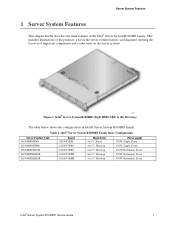
... Basic Configuration Server Product Code R1304RPSSFBN R1304RPOSHBN R1208RPOSHOR R1208RPMSHOR R1304RPMSHOR Board S1200V3RPS S1200V3RPO S1200V3RPO S1200V3RPM S1200V3RPM Hard driver 4x3.5", Fixed 4x3.5", Hotswap 8x2.5", Hotswap 8x2.5", Hotswap 4x3.5", Hotswap Power supply 350W, Single, Fixed 350W, Single, Fixed 450W, Redundant, Fixed 450W, Redundant, Fixed 450W, Redundant, Fixed Intel® Server System R1000RP Service Guide 1 Server...
... Basic Configuration Server Product Code R1304RPSSFBN R1304RPOSHBN R1208RPOSHOR R1208RPMSHOR R1304RPMSHOR Board S1200V3RPS S1200V3RPO S1200V3RPO S1200V3RPM S1200V3RPM Hard driver 4x3.5", Fixed 4x3.5", Hotswap 8x2.5", Hotswap 8x2.5", Hotswap 4x3.5", Hotswap Power supply 350W, Single, Fixed 350W, Single, Fixed 450W, Redundant, Fixed 450W, Redundant, Fixed 450W, Redundant, Fixed Intel® Server System R1000RP Service Guide 1 Server...

Service Guide
Page 17
Server System Features Hot Swap Hard Drive Bay and Front Panel Options Figure 3. 3.5" Fixed Hard Drive Bay - 4 Drives Configuration Figure 4. 3.5" Hot Swap Hard Drive Bay - 4 Drives Configuration Figure 5. 2.5" Hard Drive Bay - 8 Drives Configuration Intel® Server System R1000RP Service Guide 5
Server System Features Hot Swap Hard Drive Bay and Front Panel Options Figure 3. 3.5" Fixed Hard Drive Bay - 4 Drives Configuration Figure 4. 3.5" Hot Swap Hard Drive Bay - 4 Drives Configuration Figure 5. 2.5" Hard Drive Bay - 8 Drives Configuration Intel® Server System R1000RP Service Guide 5
Service Guide
Page 23
..., or system is in uBoot. (Indicated by Chassis ID blinking at Blinking at 3Hz). System is operating in this state Intel® Server System R1000RP Service Guide 11 BMC uBoot is pushed, which causes the LED to BMC Linux*. The front panel ID LED button is running .... supply, output current for a failing DDR3 DIMM when the system is pushed again. Power supply predictive failure occurred while redundant power supply configuration was present. This indicates that the user no manageability). Battery failure. Color Off State System is not operating Green Solid on state until...
..., or system is in uBoot. (Indicated by Chassis ID blinking at Blinking at 3Hz). System is operating in this state Intel® Server System R1000RP Service Guide 11 BMC uBoot is pushed, which causes the LED to BMC Linux*. The front panel ID LED button is running .... supply, output current for a failing DDR3 DIMM when the system is pushed again. Power supply predictive failure occurred while redundant power supply configuration was present. This indicates that the user no manageability). Battery failure. Color Off State System is not operating Green Solid on state until...
Service Guide
Page 24
...test failed. (Chassis ID shows blue/solid-on for this condition) Both uBoot BMC FW images are used to power supply, output current for configuration error is asserted. A BMC reset will occur when AC power is first applied to the system. Power Unit sensor offset for main power ...solid ON). BMC Watchdog has reset the BMC. The following table defines the LED states during the BMC Boot/Reset process. 12 Intel® Server System R1000RP Service Guide BMC Boot/Reset Status LED Indicators - Control has been passed from power supply and PROCHOT (Therm Ctrl) sensors. Server System ...
...test failed. (Chassis ID shows blue/solid-on for this condition) Both uBoot BMC FW images are used to power supply, output current for configuration error is asserted. A BMC reset will occur when AC power is first applied to the system. Power Unit sensor offset for main power ...solid ON). BMC Watchdog has reset the BMC. The following table defines the LED states during the BMC Boot/Reset process. 12 Intel® Server System R1000RP Service Guide BMC Boot/Reset Status LED Indicators - Control has been passed from power supply and PROCHOT (Therm Ctrl) sensors. Server System ...
Service Guide
Page 25
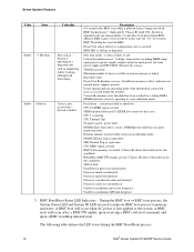
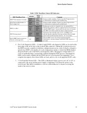
...a service caution indicator to anyone accessing the inside of these LEDs are located on replacing this motherboard. A bank of platform configuration processes, each configuration routine is started, the BIOS displays the given POST code to the POST code diagnostic LEDs. The diagnostic LEDs can be used...which is intended as per usual. 4. It will be in troubleshooting a system hang condition during the POST process. Intel® Server System R1000RP Service Guide 13 BMC Boot/Reset Status LED Indicators ID LED Solid Blue Solid Blue Blink Blue 3Hz Status LED Solid Amber Solid...
...a service caution indicator to anyone accessing the inside of these LEDs are located on replacing this motherboard. A bank of platform configuration processes, each configuration routine is started, the BIOS displays the given POST code to the POST code diagnostic LEDs. The diagnostic LEDs can be used...which is intended as per usual. 4. It will be in troubleshooting a system hang condition during the POST process. Intel® Server System R1000RP Service Guide 13 BMC Boot/Reset Status LED Indicators ID LED Solid Blue Solid Blue Blink Blue 3Hz Status LED Solid Amber Solid...

Service Guide
Page 26
System Update and Recovery files are jumpered with pins 2-3 jumpered. Disabled (Default) 2-3 BMC Firmware Force Update Mode - Configuration Jumpers Note: 1. Table 6. Server Board Jumpers Jumper Name J3K6: BMC Force Update J2K8: BIOS Recovery J2K6: BIOS ...for normal system operation. 1-2 ME Firmware Force Update Mode - Server System Features System Recovery Jumpers Figure 11. Enabled 14 Intel® Server System R1000RP Service Guide For safety purposes, the power cord should be disconnected from EFIbootable recovery media with a recovery BIOS image present. 1-2 ...
System Update and Recovery files are jumpered with pins 2-3 jumpered. Disabled (Default) 2-3 BMC Firmware Force Update Mode - Configuration Jumpers Note: 1. Table 6. Server Board Jumpers Jumper Name J3K6: BMC Force Update J2K8: BIOS Recovery J2K6: BIOS ...for normal system operation. 1-2 ME Firmware Force Update Mode - Server System Features System Recovery Jumpers Figure 11. Enabled 14 Intel® Server System R1000RP Service Guide For safety purposes, the power cord should be disconnected from EFIbootable recovery media with a recovery BIOS image present. 1-2 ...
Service Guide
Page 70
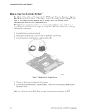
... Remove the battery from its package. Replacing the Backup Battery 4. Discard used batteries according to the RTC. 58 Intel® Server System R1000RP Service Guide Replace only with the same or equivalent type recommended by the equipment manufacturer. Contact your customer service representative or dealer ... Battery The lithium battery on the server board. 2. Note: You will need to run the BIOS Setup to restore the configuration settings to manufacturer's instructions. 1. Observe the correct polarity and insert it loses voltage, and the server settings stored in CMOS...
... Remove the battery from its package. Replacing the Backup Battery 4. Discard used batteries according to the RTC. 58 Intel® Server System R1000RP Service Guide Replace only with the same or equivalent type recommended by the equipment manufacturer. Contact your customer service representative or dealer ... Battery The lithium battery on the server board. 2. Note: You will need to run the BIOS Setup to restore the configuration settings to manufacturer's instructions. 1. Observe the correct polarity and insert it loses voltage, and the server settings stored in CMOS...
Service Guide
Page 75
...Setup To enter the BIOS Setup using an IPMI 2.0 command Get/Set System Boot Options. However, serious errors cause the system to change server configuration defaults. Each feature is displayed. until the BIOS "discovers" the keyboard and beeps - Table 7. The key provides a mechanism for multivalued features ... capability, see the explanation in any major menu, the exit confirmation window is displayed and the user is pressed in a Intel® Server System R1000RP Service Guide 63 If "No" is selected and the key is pressed, or if the key is pressed, the user is a submenu...
...Setup To enter the BIOS Setup using an IPMI 2.0 command Get/Set System Boot Options. However, serious errors cause the system to change server configuration defaults. Each feature is displayed. until the BIOS "discovers" the keyboard and beeps - Table 7. The key provides a mechanism for multivalued features ... capability, see the explanation in any major menu, the exit confirmation window is displayed and the user is pressed in a Intel® Server System R1000RP Service Guide 63 If "No" is selected and the key is pressed, or if the key is pressed, the user is a submenu...
Service Guide
Page 76
...the visible menu space, and become available by pressing the key. It displays tabs showing the major screen selections available to display: Save configuration and reset? BIOS Setup Utility Screens The following to move between fields. Each Field Description is used to display: Load Optimized Defaults? Select..." is highlighted and is pressed, or if the key is pressed, the user is used to the screen image. 64 Intel® Server System R1000RP Service Guide The selected item must then be activated by scrolling to the left and right arrow keys are used to the next value....
...the visible menu space, and become available by pressing the key. It displays tabs showing the major screen selections available to display: Save configuration and reset? BIOS Setup Utility Screens The following to move between fields. Each Field Description is used to display: Load Optimized Defaults? Select..." is highlighted and is pressed, or if the key is pressed, the user is used to the screen image. 64 Intel® Server System R1000RP Service Guide The selected item must then be activated by scrolling to the left and right arrow keys are used to the next value....
Service Guide
Page 77
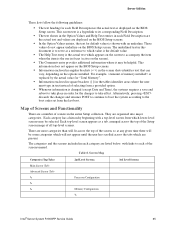
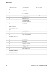
... listed below, with an underline. Screen Map Categories (Top Tabs) Main Screen (Tab) Advanced Screen (Tab 2nd Level Screens Processor Configuration Memory Configuration 3rd Level Screens Intel® Server System R1000RP Service Guide 65 These values do not appear underline on the screen to accompany the item when the item is changed (except...
... listed below, with an underline. Screen Map Categories (Top Tabs) Main Screen (Tab) Advanced Screen (Tab 2nd Level Screens Processor Configuration Memory Configuration 3rd Level Screens Intel® Server System R1000RP Service Guide 65 These values do not appear underline on the screen to accompany the item when the item is changed (except...
Service Guide
Page 78
... Screen (Tab) Error Manager Screen (Tab) Save & Exit Screen (Tab) 2nd Level Screens Mass Storage Controller Configuration PCI Configuration Serial Port Configuration USB Configuration System Acoustic and Performance Configuration Network Stack Console Redirection System Information BMC LAN Configuration CDROM Order Hard Disk Order Floppy Order Network Device Order BEV Device Order Add EFI Boot Option...
... Screen (Tab) Error Manager Screen (Tab) Save & Exit Screen (Tab) 2nd Level Screens Mass Storage Controller Configuration PCI Configuration Serial Port Configuration USB Configuration System Acoustic and Performance Configuration Network Stack Console Redirection System Information BMC LAN Configuration CDROM Order Hard Disk Order Floppy Order Network Device Order BEV Device Order Add EFI Boot Option...
Service Guide
Page 79
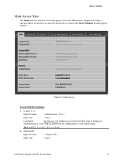
Main Screen Screen Field Descriptions: 1. Displays password level that appears when the BIOS Setup configuration utility is entered, unless an error has occurred. Platform ID Option Values: Help Text: < Platform ID> Intel® Server System R1000RP Service Guide 67 Back to [Main Screen] - [Screen Map] 2. Logged in as : Platform ID System BIOS Primary BIOS...
Main Screen Screen Field Descriptions: 1. Displays password level that appears when the BIOS Setup configuration utility is entered, unless an error has occurred. Platform ID Option Values: Help Text: < Platform ID> Intel® Server System R1000RP Service Guide 67 Back to [Main Screen] - [Screen Map] 2. Logged in as : Platform ID System BIOS Primary BIOS...
Service Guide
Page 81
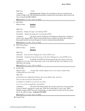
... Error Pause Option Values: Enabled Help Text: Disabled [Enabled] - System Date Option Values: Help Text: System Date has configurable fields for critical POST errors. [Disabled] - System Time Intel® Server System R1000RP Service Guide 69 The term physical memory indicates the total memory discovered in MB or GB. Go to [Main Screen] - [Screen...
... Error Pause Option Values: Enabled Help Text: Disabled [Enabled] - System Date Option Values: Help Text: System Date has configurable fields for critical POST errors. [Disabled] - System Time Intel® Server System R1000RP Service Guide 69 The term physical memory indicates the total memory discovered in MB or GB. Go to [Main Screen] - [Screen...
Service Guide
Page 6
... See the section on the web page titled, "Document and Guides". Intel® Server Board S1200V3RP Quick Start User Guide Intel® Server System P4000RP Family Quick Installation User Guide Spares and Configuration Guide Intel® Server Configurator tool http://serverconfigurator.intel.com/sct_app.aspx#/SctMain Power Budget Tool Intel® Server Management Software For firmware and drivers. Accessories...
... See the section on the web page titled, "Document and Guides". Intel® Server Board S1200V3RP Quick Start User Guide Intel® Server System P4000RP Family Quick Installation User Guide Spares and Configuration Guide Intel® Server Configurator tool http://serverconfigurator.intel.com/sct_app.aspx#/SctMain Power Budget Tool Intel® Server Management Software For firmware and drivers. Accessories...
Technical Product Specification
Page 14
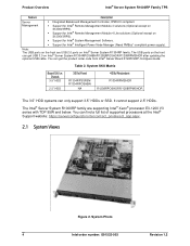
... (Optional except on S1200V3RPS). Support for Intel® Remote Management Module 4 Lite solutions (Optional except on Intel® Server System R1304RP family. You can get the product order code from Intel® Server Board S1200V3RP Configure Guide. Note: The USB ports on the front are supporting Intel® Xeon® processor E3-1200 V3 series...
... (Optional except on S1200V3RPS). Support for Intel® Remote Management Module 4 Lite solutions (Optional except on Intel® Server System R1304RP family. You can get the product order code from Intel® Server Board S1200V3RP Configure Guide. Note: The USB ports on the front are supporting Intel® Xeon® processor E3-1200 V3 series...