
Service Guide
Page 5
... as the fan, power supply, and front panel board, among other components you identify your Intel® Server System. This includes information for navigating through the BIOS Setup screens, performing a BIOS update, and resetting the password or BIOS defaults. Preface Preface About this Manual This manual is written for system technicians who are shipped...
... as the fan, power supply, and front panel board, among other components you identify your Intel® Server System. This includes information for navigating through the BIOS Setup screens, performing a BIOS update, and resetting the password or BIOS defaults. Preface Preface About this Manual This manual is written for system technicians who are shipped...
Service Guide
Page 7
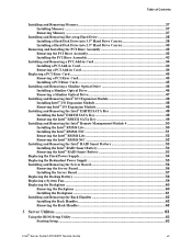
... a Slimline Optical Drive 47 Installing and Removing Intel® I/O Expansion Module 48 Installing Intel® I/O Expansion Module 48 Removing Intel® I/O Expansion Module 48 Installing and Removing the Intel® ESRTII SATA Key 49 Installing the Intel® ESRTII SATA Key 49 Removing the Intel® ESRTII SATA Key 49 Installing and Removing...61 Installing and Removing the Rack Handles 62 Installing the Rack Handles 62 Removing the Rack Handles 62 3 Server Utilities 63 Using the BIOS Setup Utility 63 Starting Setup ...63 Intel® Server System R1000RP Service Guide vii
... a Slimline Optical Drive 47 Installing and Removing Intel® I/O Expansion Module 48 Installing Intel® I/O Expansion Module 48 Removing Intel® I/O Expansion Module 48 Installing and Removing the Intel® ESRTII SATA Key 49 Installing the Intel® ESRTII SATA Key 49 Removing the Intel® ESRTII SATA Key 49 Installing and Removing...61 Installing and Removing the Rack Handles 62 Installing the Rack Handles 62 Removing the Rack Handles 62 3 Server Utilities 63 Using the BIOS Setup Utility 63 Starting Setup ...63 Intel® Server System R1000RP Service Guide vii
Service Guide
Page 8
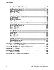
Table of Contents Setup Navigation Keyboard Commands 63 Setup Screen Menu Selection Bar 64 BIOS Setup Utility Screens 64 Map of Screens and Functionality 65 Main Screen (Tab)...67 Advanced Screen (Tab 70 Processor Configuration 72 Memory Configuration 80 Mass ... A: Technical Reference 147 System Environmental Specifications 147 Appendix B: Regulatory and Compliance Information 149 Appendix C: LED Decoder 150 Appendix D: Getting Help 154 Warranty Information 154 Appendix E: Intel® Server Issue Report Form 155 viii Intel® Server System R1000RP Service Guide
Table of Contents Setup Navigation Keyboard Commands 63 Setup Screen Menu Selection Bar 64 BIOS Setup Utility Screens 64 Map of Screens and Functionality 65 Main Screen (Tab)...67 Advanced Screen (Tab 70 Processor Configuration 72 Memory Configuration 80 Mass ... A: Technical Reference 147 System Environmental Specifications 147 Appendix B: Regulatory and Compliance Information 149 Appendix C: LED Decoder 150 Appendix D: Getting Help 154 Warranty Information 154 Appendix E: Intel® Server Issue Report Form 155 viii Intel® Server System R1000RP Service Guide
Service Guide
Page 12
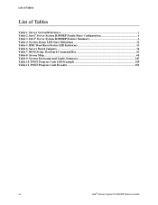
...; Server System R1000RP Service Guide List of Tables List of Tables Table 1. System Status LED State Definitions 11 Table 5. Intel® Server System R1000RP Feature Summary 2 Table 4. BIOS Setup: Keyboard Command Bar 63 Table 8. System Environmental Limits Summary 147 Table 10. POST Progress Code LED Example 150 Table 11. BMC Boot/Reset...
...; Server System R1000RP Service Guide List of Tables List of Tables Table 1. System Status LED State Definitions 11 Table 5. Intel® Server System R1000RP Feature Summary 2 Table 4. BIOS Setup: Keyboard Command Bar 63 Table 8. System Environmental Limits Summary 147 Table 10. POST Progress Code LED Example 150 Table 11. BMC Boot/Reset...
Service Guide
Page 25
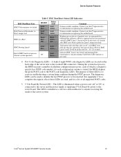
... is running . Server will be executed. During the system boot process, the BIOS executes a number of eight POST code diagnostic LEDs are read, and for information on replacing this motherboard. Intel® Server System R1000RP Service Guide 13 Post Code Diagnostic LEDs - Contact your... Intel® representative for information on the back edge of which is started, the BIOS displays the given POST code to BMC Linux*....
... is running . Server will be executed. During the system boot process, the BIOS executes a number of eight POST code diagnostic LEDs are read, and for information on replacing this motherboard. Intel® Server System R1000RP Service Guide 13 Post Code Diagnostic LEDs - Contact your... Intel® representative for information on the back edge of which is started, the BIOS displays the given POST code to BMC Linux*....

Service Guide
Page 26
... from EFIbootable recovery media with a recovery BIOS image present. 1-2 These pins should have a jumper in place for normal system operation. 1-2 ME Firmware Force Update Mode - Disabled (Default) 2-3 ME Firmware Force Update Mode - Enabled 14 Intel® Server System R1000RP Service Guide System... a system before removing any system components or moving any of the on http://www.intel.com/support/. Server Board Jumpers Jumper Name J3K6: BMC Force Update J2K8: BIOS Recovery J2K6: BIOS Default J3K2: ME Force Update Pins System Results 1-2 BMC Firmware Force Update Mode -...
... from EFIbootable recovery media with a recovery BIOS image present. 1-2 These pins should have a jumper in place for normal system operation. 1-2 ME Firmware Force Update Mode - Disabled (Default) 2-3 ME Firmware Force Update Mode - Enabled 14 Intel® Server System R1000RP Service Guide System... a system before removing any system components or moving any of the on http://www.intel.com/support/. Server Board Jumpers Jumper Name J3K6: BMC Force Update J2K8: BIOS Recovery J2K6: BIOS Default J3K2: ME Force Update Pins System Results 1-2 BMC Firmware Force Update Mode -...
Service Guide
Page 70
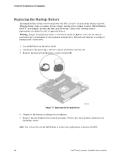
... of approved devices. Warning: Danger of the battery according to release the battery (see letter B). Figure 75. Discard used batteries according to the RTC. 58 Intel® Server System R1000RP Service Guide Gently press the metal clip as shown to local ordinance. 5. Dispose of explosion if battery is incorrectly replaced. Note...
... of approved devices. Warning: Danger of the battery according to release the battery (see letter B). Figure 75. Discard used batteries according to the RTC. 58 Intel® Server System R1000RP Service Guide Gently press the metal clip as shown to local ordinance. 5. Dispose of explosion if battery is incorrectly replaced. Note...
Service Guide
Page 75
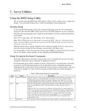
...using a keyboard (or emulated keyboard), press the function key during boot time when the OEM or Intel Logo Screen or the POST Diagnostic Screen is displayed initially. Starting Setup To enter the BIOS Setup using an IPMI 2.0 command Get/Set System Boot Options. It is reentered. The key ... option chosen and in any field. Each feature is associated with or without affecting any submenu, the parent menu is pressed in a Intel® Server System R1000RP Service Guide 63 Each value field contains configurable parameters. When the key is re-entered. The up arrow is...
...using a keyboard (or emulated keyboard), press the function key during boot time when the OEM or Intel Logo Screen or the POST Diagnostic Screen is displayed initially. Starting Setup To enter the BIOS Setup using an IPMI 2.0 command Get/Set System Boot Options. It is reentered. The key ... option chosen and in any field. Each feature is associated with or without affecting any submenu, the parent menu is pressed in a Intel® Server System R1000RP Service Guide 63 Each value field contains configurable parameters. When the key is re-entered. The up arrow is...
Service Guide
Page 76
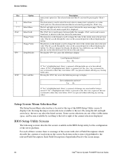
...and the Setup is located at the top of the current item to where they were before was pressed without displaying the full list. BIOS Setup Utility Screens The following sections describe the screens available in the associated pick list without affecting any existing field values. If "No"...+ Change Value Setup Defaults Save and Exit Description menu item's option list. Each Field Description is hyperlinked to the screen image. 64 Intel® Server System R1000RP Service Guide Each item on the keypad is returned to display: Save configuration and reset?
...and the Setup is located at the top of the current item to where they were before was pressed without displaying the full list. BIOS Setup Utility Screens The following sections describe the screens available in the associated pick list without affecting any existing field values. If "No"...+ Change Value Setup Defaults Save and Exit Description menu item's option list. Each Field Description is hyperlinked to the screen image. 64 Intel® Server System R1000RP Service Guide Each item on the keypad is returned to display: Save configuration and reset?
Service Guide
Page 77
...These lists follow the following guidelines: The text heading for each Field Description is the actual text as displayed on the BIOS Setup screen. This screen text is shown with an underline. Each top-level screen appears as a reference to which value is the... (Tab) Advanced Screen (Tab 2nd Level Screens Processor Configuration Memory Configuration 3rd Level Screens Intel® Server System R1000RP Service Guide 65 This information does not appear on the BIOS Setup screens. Information enclosed in angular brackets (< >) in the screen shots identifies text...
...These lists follow the following guidelines: The text heading for each Field Description is the actual text as displayed on the BIOS Setup screen. This screen text is shown with an underline. Each top-level screen appears as a reference to which value is the... (Tab) Advanced Screen (Tab 2nd Level Screens Processor Configuration Memory Configuration 3rd Level Screens Intel® Server System R1000RP Service Guide 65 This information does not appear on the BIOS Setup screens. Information enclosed in angular brackets (< >) in the screen shots identifies text...
Service Guide
Page 79
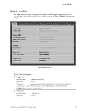
... to [Main Screen] - [Screen Map] 2. Logged in : Administrator or User. Displays password level that appears when the BIOS Setup configuration utility is the default mode. Platform ID Option Values: Help Text: < Platform ID> Intel® Server System R1000RP Service Guide 67 Main Screen Screen Field Descriptions: 1. Main Advanced Security Server Management Boot...
... to [Main Screen] - [Screen Map] 2. Logged in : Administrator or User. Displays password level that appears when the BIOS Setup configuration utility is the default mode. Platform ID Option Values: Help Text: < Platform ID> Intel® Server System R1000RP Service Guide 67 Main Screen Screen Field Descriptions: 1. Main Advanced Security Server Management Boot...
Service Guide
Page 80
...this is taken from the BIOS ID String, with the timestamp segment dropped off . Back to [Main Screen] - [Screen Map] 6. The version information displayed is executing POST. Total Memory Option Values: 68 Intel® Server System R1000RP ...Service Guide Build Date Option Values: Help Text: Comments: Information only. Server Utilities Comments: Information only. The version information displayed is the correct platform BIOS 86B: Identifies this BIOS as being an EPSD Server BIOS xx: Major Revision level of the BIOS...
...this is taken from the BIOS ID String, with the timestamp segment dropped off . Back to [Main Screen] - [Screen Map] 6. The version information displayed is executing POST. Total Memory Option Values: 68 Intel® Server System R1000RP ...Service Guide Build Date Option Values: Help Text: Comments: Information only. Server Utilities Comments: Information only. The version information displayed is the correct platform BIOS 86B: Identifies this BIOS as being an EPSD Server BIOS xx: Major Revision level of the BIOS...
Service Guide
Page 81
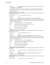
... and the text mode Diagnostic Screen is reset by this setting. Minor and fatal error displays are not affected by the "BIOS Defaults" jumper, BIOS Recovery Flash Update, or other method, the date will initially display the current system day of installed DDR3 DIMMs. Back to...[Enabled] - Attempt to boot and do not go to [Main Screen] - [Screen Map] 7. Display the diagnostic screen during POST. System Time Intel® Server System R1000RP Service Guide 69 Back to modify the selected field. It may be between 2005 and 2099. The year must be edited...
... and the text mode Diagnostic Screen is reset by this setting. Minor and fatal error displays are not affected by the "BIOS Defaults" jumper, BIOS Recovery Flash Update, or other method, the date will initially display the current system day of installed DDR3 DIMMs. Back to...[Enabled] - Attempt to boot and do not go to [Main Screen] - [Screen Map] 7. Display the diagnostic screen during POST. System Time Intel® Server System R1000RP Service Guide 69 Back to modify the selected field. It may be between 2005 and 2099. The year must be edited...
Service Guide
Page 82
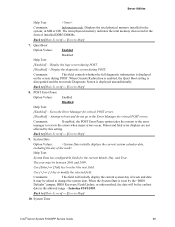
Server Utilities Option Values: hour format>
Server Utilities Option Values: hour format>
Service Guide
Page 89
...to be "always enabled". Report the I /O (Intel® VT-d). Intel® Server System R1000RP Service Guide 77 The OS and applications installed must support this will override the BIOS setting, and the number selected by BIOS will be powered off and then back on the ... Values: Enabled Disabled Help Text: Enable/Disable Intel® VT-d Interrupt Remapping support. Execute Disable Bit Option Values: Enabled Disabled Help Text: Execute Disable Bit can control the number of active cores independently of the BIOS Setup setting. Comments: This option is only ...
...to be "always enabled". Report the I /O (Intel® VT-d). Intel® Server System R1000RP Service Guide 77 The OS and applications installed must support this will override the BIOS setting, and the number selected by BIOS will be powered off and then back on the ... Values: Enabled Disabled Help Text: Enable/Disable Intel® VT-d Interrupt Remapping support. Execute Disable Bit Option Values: Enabled Disabled Help Text: Execute Disable Bit can control the number of active cores independently of the BIOS Setup setting. Comments: This option is only ...
Service Guide
Page 92
... default] Help Text: 20ms to 3000ms. Millisecond timeout waiting for the SMI Handler to respond to the Advanced screen, then select the desired screen. 80 Intel® Server System R1000RP Service Guide Range is Comments: Amount of time to allow for BSP and APs to [Advanced Screen] - [Screen Map] 28. If... Map] Memory Configuration The Memory Configuration screen allows the user to view details about the DDR3 DIMMs that are installed as system memory, and alter BIOS Memory Configuration settings where appropriate.
... default] Help Text: 20ms to 3000ms. Millisecond timeout waiting for the SMI Handler to respond to the Advanced screen, then select the desired screen. 80 Intel® Server System R1000RP Service Guide Range is Comments: Amount of time to allow for BSP and APs to [Advanced Screen] - [Screen Map] 28. If... Map] Memory Configuration The Memory Configuration screen allows the user to view details about the DDR3 DIMMs that are installed as system memory, and alter BIOS Memory Configuration settings where appropriate.

Service Guide
Page 95
...Storage Configuration screen allows the user to the Advanced screen, then select the desired screen. Intel® Server System R1000RP Service Guide 83 DIMM_B1 9. DIMM_B2 Help Text: Comments: Information ...in GB of that are also informational displays of channels and slots - S1200RP boards can have the same number of AHCI controller configuration, and SATA ...DIMM socket present on Channel A, Slot 2. There are integrated into the server board on which the BIOS is dependent on the board. Server Utilities Back to [Memory Configuration Screen] - [Advanced Screen] ...
...Storage Configuration screen allows the user to the Advanced screen, then select the desired screen. Intel® Server System R1000RP Service Guide 83 DIMM_B1 9. DIMM_B2 Help Text: Comments: Information ...in GB of that are also informational displays of channels and slots - S1200RP boards can have the same number of AHCI controller configuration, and SATA ...DIMM socket present on Channel A, Slot 2. There are integrated into the server board on which the BIOS is dependent on the board. Server Utilities Back to [Memory Configuration Screen] - [Advanced Screen] ...
Service Guide
Page 99
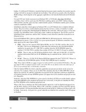
Comments: When this option is enabled, BIOS makes as much memory available as possible in the 32-bit (4GB) address space, by limiting the amount of PCI/PCIe Memory Address Space and ... Configuration Screen] - [Advanced Screen] - [Screen Map] 2. Maximize Memory below 4GB Option Values: Enabled Disabled Help Text: BIOS maximizes memory usage below 4GB Memory Mapped I/O above 4 GB Memory Mapped I /O above 4 GB Option Values: Enabled Disabled Intel® Server System R1000RP Service Guide 87 Only enable for a 32-bit OS without PAE capability or...
Comments: When this option is enabled, BIOS makes as much memory available as possible in the 32-bit (4GB) address space, by limiting the amount of PCI/PCIe Memory Address Space and ... Configuration Screen] - [Advanced Screen] - [Screen Map] 2. Maximize Memory below 4GB Option Values: Enabled Disabled Help Text: BIOS maximizes memory usage below 4GB Memory Mapped I/O above 4 GB Memory Mapped I /O above 4 GB Option Values: Enabled Disabled Intel® Server System R1000RP Service Guide 87 Only enable for a 32-bit OS without PAE capability or...

Service Guide
Page 101
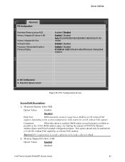
... the Main screen, select Advanced > PCI Configuration > NIC Configuration. There are several possible types of description to go to go into Setup.) Intel® I210 Dual-Port Gigabit Ethernet Controller (Springville) For boards with add-in network adapter cards. Back to [NIC Configuration Screen] - ...SFP+ Module (Niantic) Intel® 82575EB Dual-Port Gigabit Module (Zoar) Mellanox* ConnectX-3* Single-Port InfiniBand FD14 Module For the IO Module entries on the NIC Configuration screen, only entries for modules which are boards which are displayed for BIOS POST. The number of...
... the Main screen, select Advanced > PCI Configuration > NIC Configuration. There are several possible types of description to go to go into Setup.) Intel® I210 Dual-Port Gigabit Ethernet Controller (Springville) For boards with add-in network adapter cards. Back to [NIC Configuration Screen] - ...SFP+ Module (Niantic) Intel® 82575EB Dual-Port Gigabit Module (Zoar) Mellanox* ConnectX-3* Single-Port InfiniBand FD14 Module For the IO Module entries on the NIC Configuration screen, only entries for modules which are boards which are displayed for BIOS POST. The number of...
Service Guide
Page 102
...ports on an add-in its speed class. When a NIC controller is installed than InfiniBand controllers, there will be enabled. Advanced 90 Intel® Server System R1000RP Service Guide For non-InfiniBand NICs, there are different OPROMs for different protocols, which is enabled, then neither PXE... When it will be disabled and grayed out, and the MAC Address will be disabled Note: These Option ROMs are also differentiated by BIOS. Conversely, if all ports for 10 Gb NICs. For each other for a given controller are displayed. There are two separate PXE Option...
...ports on an add-in its speed class. When a NIC controller is installed than InfiniBand controllers, there will be enabled. Advanced 90 Intel® Server System R1000RP Service Guide For non-InfiniBand NICs, there are different OPROMs for different protocols, which is enabled, then neither PXE... When it will be disabled and grayed out, and the MAC Address will be disabled Note: These Option ROMs are also differentiated by BIOS. Conversely, if all ports for 10 Gb NICs. For each other for a given controller are displayed. There are two separate PXE Option...