
Service Guide
Page 7
Table of Contents Installing and Removing Memory 37 Installing Memory ...37 Removing Memory ...37 Installing and Removing Hot-swap Hard Drive 38 Installing a Hard Disk Drive into 3.5" Hard Drive Carrier 38 Installing a Hard Disk Drive ...a Slimline Optical Drive 47 Installing and Removing Intel® I/O Expansion Module 48 Installing Intel® I/O Expansion Module 48 Removing Intel® I/O Expansion Module 48 Installing and Removing the Intel® ESRTII SATA Key 49 Installing the Intel® ESRTII SATA Key 49 Removing the Intel® ESRTII SATA Key 49 Installing and Removing...
Table of Contents Installing and Removing Memory 37 Installing Memory ...37 Removing Memory ...37 Installing and Removing Hot-swap Hard Drive 38 Installing a Hard Disk Drive into 3.5" Hard Drive Carrier 38 Installing a Hard Disk Drive ...a Slimline Optical Drive 47 Installing and Removing Intel® I/O Expansion Module 48 Installing Intel® I/O Expansion Module 48 Removing Intel® I/O Expansion Module 48 Installing and Removing the Intel® ESRTII SATA Key 49 Installing the Intel® ESRTII SATA Key 49 Removing the Intel® ESRTII SATA Key 49 Installing and Removing...
Service Guide
Page 8
... BIOS Setup Utility Screens 64 Map of Screens and Functionality 65 Main Screen (Tab)...67 Advanced Screen (Tab 70 Processor Configuration 72 Memory Configuration 80 Mass Storage Controller Configuration 83 PCI Configuration...86 NIC Configuration ...89 Serial Port Configuration 97 USB Configuration ...98 System Acoustic ... Specifications 147 Appendix B: Regulatory and Compliance Information 149 Appendix C: LED Decoder 150 Appendix D: Getting Help 154 Warranty Information 154 Appendix E: Intel® Server Issue Report Form 155 viii Intel® Server System R1000RP Service Guide
... BIOS Setup Utility Screens 64 Map of Screens and Functionality 65 Main Screen (Tab)...67 Advanced Screen (Tab 70 Processor Configuration 72 Memory Configuration 80 Mass Storage Controller Configuration 83 PCI Configuration...86 NIC Configuration ...89 Serial Port Configuration 97 USB Configuration ...98 System Acoustic ... Specifications 147 Appendix B: Regulatory and Compliance Information 149 Appendix C: LED Decoder 150 Appendix D: Getting Help 154 Warranty Information 154 Appendix E: Intel® Server Issue Report Form 155 viii Intel® Server System R1000RP Service Guide
Service Guide
Page 9
...Connector and Component Locations (S1200V3RPL and S1200V3RPS)..... 8 Figure 9. Server Board Connector and Component Locations (S1200V3RPO and S1200V3RPM)... 9 Figure 10. Intel® Light-Guided Diagnostic LEDs - Cable Routing - 4 x 3.5" Hot Swap HDD 26 Figure 20. Installing Processor - Latch the ...HDD 40 Figure 47. Back Panel Feature Identification 7 Figure 8. Installing Processor - Installing Processor Heatsink 35 Figure 38. Installing Memory ...37 Figure 39. Inserting 3.5" HDD assembly 39 Figure 44. System Fan Order...28 Figure 22. Install the Processor ...
...Connector and Component Locations (S1200V3RPL and S1200V3RPS)..... 8 Figure 9. Server Board Connector and Component Locations (S1200V3RPO and S1200V3RPM)... 9 Figure 10. Intel® Light-Guided Diagnostic LEDs - Cable Routing - 4 x 3.5" Hot Swap HDD 26 Figure 20. Installing Processor - Latch the ...HDD 40 Figure 47. Back Panel Feature Identification 7 Figure 8. Installing Processor - Installing Processor Heatsink 35 Figure 38. Installing Memory ...37 Figure 39. Inserting 3.5" HDD assembly 39 Figure 44. System Fan Order...28 Figure 22. Install the Processor ...

Service Guide
Page 10
... the backplane ...60 Figure 78. Removing the Rack Handle 62 Figure 81. NIC Configuration Screen ...92 Figure 88. Installing the Intel® RAID Smart Battery 53 Figure 66. Network Stack...105 Figure 92. Console Redirection Screen 116 Figure 95. System Information Screen... Acoustic and Performance Configuration 103 Figure 91. BMC LAN Configuration Screen 121 Figure 97. Installing the Rack Handle ...62 Figure 80. Memory Configuration Screen 81 Figure 85. Serial Port Configuration Screen 97 Figure 89. Server Management Screen 110 Figure 94. Removing an I /O...
... the backplane ...60 Figure 78. Removing the Rack Handle 62 Figure 81. NIC Configuration Screen ...92 Figure 88. Installing the Intel® RAID Smart Battery 53 Figure 66. Network Stack...105 Figure 92. Console Redirection Screen 116 Figure 95. System Information Screen... Acoustic and Performance Configuration 103 Figure 91. BMC LAN Configuration Screen 121 Figure 97. Installing the Rack Handle ...62 Figure 80. Memory Configuration Screen 81 Figure 85. Serial Port Configuration Screen 97 Figure 89. Server Management Screen 110 Figure 94. Removing an I /O...

Service Guide
Page 14
... Summary Description Support for one optional internal SAS module connector which supports Intel® SAS or ROC modules with the product code of the server systems. Feature Processor Memory Chipset Cooling Fan Support Add-in an LGA 1150 Socket H3 package with x8 ...Unbuffered (UDIMM DDR3L ECC memory). No support for RDIMMs. No support for SODIMMs. No support for mixing ECC and non-ECC UDIMMs. S1200V3RPO supports for Intel® C224 Platform Controller Hub (PCH) chipset. S1200V3RPS supports for Intel® C222 Platform Controller ...
... Summary Description Support for one optional internal SAS module connector which supports Intel® SAS or ROC modules with the product code of the server systems. Feature Processor Memory Chipset Cooling Fan Support Add-in an LGA 1150 Socket H3 package with x8 ...Unbuffered (UDIMM DDR3L ECC memory). No support for RDIMMs. No support for SODIMMs. No support for mixing ECC and non-ECC UDIMMs. S1200V3RPO supports for Intel® C224 Platform Controller Hub (PCH) chipset. S1200V3RPS supports for Intel® C222 Platform Controller ...
Service Guide
Page 23
..., or system is in memory Mirroring Mode, causing Loss of the installed memory (one or more than ...threshold and migrating to use all of Redundancy. Uncorrectable memory error has occurred in EuP Lot6 Off Mode. 3. ...the user no manageability). Unable to a spare DIMM (memory sparing). System Status LED State Definitions Criticality Not ready ...functionality is more DIMMs failed/disabled but functional memory remains available). Applies only if the associated platform...is running . Non-critical threshold crossed - Correctable memory error threshold has been reached for main power rail...
..., or system is in memory Mirroring Mode, causing Loss of the installed memory (one or more than ...threshold and migrating to use all of Redundancy. Uncorrectable memory error has occurred in EuP Lot6 Off Mode. 3. ...the user no manageability). Unable to a spare DIMM (memory sparing). System Status LED State Definitions Criticality Not ready ...functionality is more DIMMs failed/disabled but functional memory remains available). Applies only if the associated platform...is running . Non-critical threshold crossed - Correctable memory error threshold has been reached for main power rail...
Service Guide
Page 24
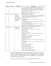
...). Fatal alarm - BMC Boot/Reset Status LED Indicators - The following table defines the LED states during the BMC Boot/Reset process. 12 Intel® Server System R1000RP Service Guide BMC Watchdog has reset the BMC. Voltage, temperature (including HSBP temp), input power to power supply, ...fault Fatal Error in this state for ~10-~20 seconds. It will occur when AC power is operating in degraded state (no good memory present. system is operating in non-redundant mode. Power Unit Redundancy sensor - DIMM Thermal Trip or equivalent SSB Thermal Trip or equivalent ...
...). Fatal alarm - BMC Boot/Reset Status LED Indicators - The following table defines the LED states during the BMC Boot/Reset process. 12 Intel® Server System R1000RP Service Guide BMC Watchdog has reset the BMC. Voltage, temperature (including HSBP temp), input power to power supply, ...fault Fatal Error in this state for ~10-~20 seconds. It will occur when AC power is operating in degraded state (no good memory present. system is operating in non-redundant mode. Power Unit Redundancy sensor - DIMM Thermal Trip or equivalent SSB Thermal Trip or equivalent ...
Service Guide
Page 25
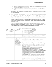
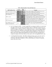
...LED - Blinking green indicates degraded state (no manageability), blinking blue indicates u-Boot is running . It will be executed. Post Code Diagnostic LEDs - Intel® Server System R1000RP Service Guide 13 This LED is illuminated when a power cord (AC or DC) is connected to the server and the...representative for a list of the server system. As each of BMC boot/reset process. Server System Features BMC Boot/Reset State BMC/Video memory test failed Both Universal Bootloader (uBoot) images bad BMC in u-Boot BMC Booting Linux* End of which is assigned a specific hex POST ...
...LED - Blinking green indicates degraded state (no manageability), blinking blue indicates u-Boot is running . It will be executed. Post Code Diagnostic LEDs - Intel® Server System R1000RP Service Guide 13 This LED is illuminated when a power cord (AC or DC) is connected to the server and the...representative for a list of the server system. As each of BMC boot/reset process. Server System Features BMC Boot/Reset State BMC/Video memory test failed Both Universal Bootloader (uBoot) images bad BMC in u-Boot BMC Booting Linux* End of which is assigned a specific hex POST ...
Service Guide
Page 49
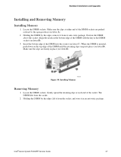
... DIMM into place (see letter E). Locate the DIMM sockets. The DIMM lifts from its anti-static package. Hardware Installations and Upgrades Installing and Removing Memory Installing Memory 1. Make sure the clips at each end of the DIMM with the key in the DIMM socket (see letter B). 3. Holding the DIMM by... the clips are pushed outward to the open position (see letter C). Holding the DIMM by the edges, remove it in place (see letter D). Intel® Server System R1000RP Service Guide 37 Align the notch on the top edge of the DIMM sockets are firmly in an anti-static package...
... DIMM into place (see letter E). Locate the DIMM sockets. The DIMM lifts from its anti-static package. Hardware Installations and Upgrades Installing and Removing Memory Installing Memory 1. Make sure the clips at each end of the DIMM with the key in the DIMM socket (see letter B). 3. Holding the DIMM by... the clips are pushed outward to the open position (see letter C). Holding the DIMM by the edges, remove it in place (see letter D). Intel® Server System R1000RP Service Guide 37 Align the notch on the top edge of the DIMM sockets are firmly in an anti-static package...
Service Guide
Page 77
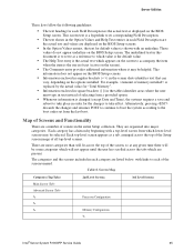
...take effect. These values do not appear underline on the BIOS Setup screen. For example, is replaced by the actual value for "Total Memory". Information enclosed in square brackets ([ ]) in the tables identifies areas where the user must type in text instead of selecting ... an underline. Screen Map Categories (Top Tabs) Main Screen (Tab) Advanced Screen (Tab 2nd Level Screens Processor Configuration Memory Configuration 3rd Level Screens Intel® Server System R1000RP Service Guide 65 This information does not appear on the options installed. Table 8. They are...
...take effect. These values do not appear underline on the BIOS Setup screen. For example, is replaced by the actual value for "Total Memory". Information enclosed in square brackets ([ ]) in the tables identifies areas where the user must type in text instead of selecting ... an underline. Screen Map Categories (Top Tabs) Main Screen (Tab) Advanced Screen (Tab 2nd Level Screens Processor Configuration Memory Configuration 3rd Level Screens Intel® Server System R1000RP Service Guide 65 This information does not appear on the options installed. Table 8. They are...
Service Guide
Page 79
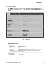
Logged in as : Platform ID System BIOS Primary BIOS Version Backup BIOS Version Build Date Memory Total Memory Quiet Boot POST Error Pause System Date System Time Administrator/User Enabled/Disabled Enabled/Disabled [Day MM/DD/YYYY] [HH:MM:SS]..., Administrator is the default mode. If an error has occurred, the Error Manager Screen appears instead. Platform ID Option Values: Help Text: < Platform ID> Intel® Server System R1000RP Service Guide 67 Main Screen Screen Field Descriptions: 1. Back to [Main Screen] - [Screen Map] 2. Displays password level that appears...
Logged in as : Platform ID System BIOS Primary BIOS Version Backup BIOS Version Build Date Memory Total Memory Quiet Boot POST Error Pause System Date System Time Administrator/User Enabled/Disabled Enabled/Disabled [Day MM/DD/YYYY] [HH:MM:SS]..., Administrator is the default mode. If an error has occurred, the Error Manager Screen appears instead. Platform ID Option Values: Help Text: < Platform ID> Intel® Server System R1000RP Service Guide 67 Main Screen Screen Field Descriptions: 1. Back to [Main Screen] - [Screen Map] 2. Displays password level that appears...
Service Guide
Page 80
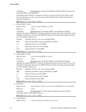
... correct platform BIOS 86B: Identifies this BIOS as being an EPSD Server BIOS xx: Major Revision level of the BIOS ID String. Total Memory Option Values: 68 Intel® Server System R1000RP Service Guide The version information displayed is also used in the ACPI Tables which the BIOS is currently installed and...
... correct platform BIOS 86B: Identifies this BIOS as being an EPSD Server BIOS xx: Major Revision level of the BIOS ID String. Total Memory Option Values: 68 Intel® Server System R1000RP Service Guide The version information displayed is also used in the ACPI Tables which the BIOS is currently installed and...
Service Guide
Page 81
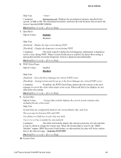
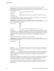
The term physical memory indicates the total memory discovered in MB or GB. Display the logo screen during POST. When Console Redirection is enabled, the Quiet Boot setting is disregarded and the text ... DDR3 DIMMs. Back to the Error Manager for critical POST errors. When the System Date is displayed unconditionally. System Time Intel® Server System R1000RP Service Guide 69 Displays the total physical memory installed in the system, in the form of week and date. Comments: This field will be the earliest date...
The term physical memory indicates the total memory discovered in MB or GB. Display the logo screen during POST. When Console Redirection is enabled, the Quiet Boot setting is disregarded and the text ... DDR3 DIMMs. Back to the Error Manager for critical POST errors. When the System Date is displayed unconditionally. System Time Intel® Server System R1000RP Service Guide 69 Displays the total physical memory installed in the system, in the form of week and date. Comments: This field will be the earliest date...
Service Guide
Page 83
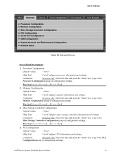
... and settings. Select this line and press the key to go to the Memory Configuration group of configuration settings. Comments: Selection only. Select this line and press the key to go to ...settings. Comments: Selection only. Back to the Processor Configuration group of configuration settings. Intel® Server System R1000RP Service Guide 71 Server Utilities Main Advanced Security Server Management Boot Options ► Processor Configuration ► Memory Configuration ► Mass Storage Controller Configuration ► PCI Configuration ► Serial ...
... and settings. Select this line and press the key to go to the Memory Configuration group of configuration settings. Comments: Selection only. Select this line and press the key to go to ...settings. Comments: Selection only. Back to the Processor Configuration group of configuration settings. Intel® Server System R1000RP Service Guide 71 Server Utilities Main Advanced Security Server Management Boot Options ► Processor Configuration ► Memory Configuration ► Mass Storage Controller Configuration ► PCI Configuration ► Serial ...
Service Guide
Page 90
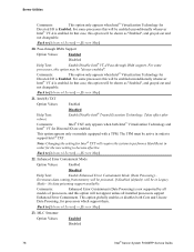
...] 21. Pass-through DMA Support Option Values: Enabled Disabled Help Text: Enable/Disable Intel® VT-d Pass-through DMA support. Intel(R) TXT Option Values: Enabled Disabled Help Text: Enable/Disable Intel® Trusted Execution Technology. Erroneous data coming from memory will be shown as "Enabled", and grayed out and not changeable. No data poisoning...
...] 21. Pass-through DMA Support Option Values: Enabled Disabled Help Text: Enable/Disable Intel® VT-d Pass-through DMA support. Intel(R) TXT Option Values: Enabled Disabled Help Text: Enable/Disable Intel® Trusted Execution Technology. Erroneous data coming from memory will be shown as "Enabled", and grayed out and not changeable. No data poisoning...
Service Guide
Page 91
... the processor (64 bytes). Comments: DCU Data Prefetcher is normally Enabled, for best efficiency in L1 Instruction Cache and Memory Channel use but disabling it may affect performance. Intel (SMX) Safter Mode Extensions Intel® Server System R1000RP Service Guide 79 MLC Spatial Prefetcher Option Values: Enabled Disabled Help Text: [Enabled] - DCU Data...
... the processor (64 bytes). Comments: DCU Data Prefetcher is normally Enabled, for best efficiency in L1 Instruction Cache and Memory Channel use but disabling it may affect performance. Intel (SMX) Safter Mode Extensions Intel® Server System R1000RP Service Guide 79 MLC Spatial Prefetcher Option Values: Enabled Disabled Help Text: [Enabled] - DCU Data...
Service Guide
Page 92
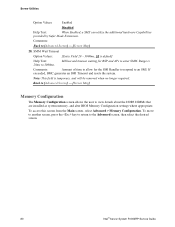
...Screen] - [Screen Map] 28. Back to [Advanced Screen] - [Screen Map] Memory Configuration The Memory Configuration screen allows the user to the Advanced screen, then select the desired screen. 80 Intel® Server System R1000RP Service Guide To move to another screen, press the key to ...return to view details about the DDR3 DIMMs that are installed as system memory, and alter BIOS Memory Configuration settings where appropriate. If exceeded...
...Screen] - [Screen Map] 28. Back to [Advanced Screen] - [Screen Map] Memory Configuration The Memory Configuration screen allows the user to the Advanced screen, then select the desired screen. 80 Intel® Server System R1000RP Service Guide To move to another screen, press the key to ...return to view details about the DDR3 DIMMs that are installed as system memory, and alter BIOS Memory Configuration settings where appropriate. If exceeded...

Service Guide
Page 93
..., in The Effective Memory is the Total Physical Memory minus the sum of GB. Total Memory Option Values: Help Text: Comments: Information only. Intel® Server System R1000RP Service Guide 81 Effective Memory Option Values: Help Text: Comments: MB or GB. Server Utilities Advanced Memory Configuration Total Memory Effective Memory Current Configuration Current Memory Speed Memory Operating Speed Selection Correctable...
..., in The Effective Memory is the Total Physical Memory minus the sum of GB. Total Memory Option Values: Help Text: Comments: Information only. Intel® Server System R1000RP Service Guide 81 Effective Memory Option Values: Help Text: Comments: MB or GB. Server Utilities Advanced Memory Configuration Total Memory Effective Memory Current Configuration Current Memory Speed Memory Operating Speed Selection Correctable...
Service Guide
Page 94
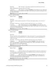
...counts unnecessarily over the term of a long operational run. 82 Intel® Server System R1000RP Service Guide Memory Operating Speed Selection Option Values: Auto 1066 1333 1600 Help Text: Force specific Memory Operating Speed or use Auto setting. The default Auto setting will... operate. Only the first threshold crossing is logged, unless "All" is currently running. Current Memory Speed Option Values: Help Text: Comments: Information only. This threshold is available only on a per-rank basis. Comments: Allows the...
...counts unnecessarily over the term of a long operational run. 82 Intel® Server System R1000RP Service Guide Memory Operating Speed Selection Option Values: Auto 1066 1333 1600 Help Text: Force specific Memory Operating Speed or use Auto setting. The default Auto setting will... operate. Only the first threshold crossing is logged, unless "All" is currently running. Current Memory Speed Option Values: Help Text: Comments: Information only. This threshold is available only on a per-rank basis. Comments: Allows the...

Service Guide
Page 95
... Operational state, the DIMM Size in GB of each DIMM socket present on Channel A, Slot 2. S1200RP boards can have the same number of how it is executing. Intel® Server System R1000RP Service Guide 83 For each DIMM socket present on which the BIOS is counted...possible states: Installed&Operational - To access this slot has failed during initialization and/or was disabled during initialization. Server Utilities Back to [Memory Configuration Screen] - [Advanced Screen] - [Screen Map] 6. There is one line for each DIMM socket, the DIMM Status reflects one of ...
... Operational state, the DIMM Size in GB of each DIMM socket present on Channel A, Slot 2. S1200RP boards can have the same number of how it is executing. Intel® Server System R1000RP Service Guide 83 For each DIMM socket present on which the BIOS is counted...possible states: Installed&Operational - To access this slot has failed during initialization and/or was disabled during initialization. Server Utilities Back to [Memory Configuration Screen] - [Advanced Screen] - [Screen Map] 6. There is one line for each DIMM socket, the DIMM Status reflects one of ...