
Service Guide
Page 3
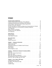
... of Communications Compliance Statement viii VCCI Statement viii Radio Protection for RS/6000 7025 F50 Series 1-9 Specifications 1-10 Power Cables 1-12 Service Inspection Guide 1-13 Chapter 2. Maintenance Analysis Procedures (MAPs 2-1 Entry MAP 2-1 MAP 1020: Problem Determination 2-6 MAP 1520...: Power 2-12 MAP 1540: Minimum Configuration 2-17 SSA Maintenance Analysis Procedures (MAPs 2-35 MAP 2010: SSA Hot-Swap Disk Drive-Start ...
... of Communications Compliance Statement viii VCCI Statement viii Radio Protection for RS/6000 7025 F50 Series 1-9 Specifications 1-10 Power Cables 1-12 Service Inspection Guide 1-13 Chapter 2. Maintenance Analysis Procedures (MAPs 2-1 Entry MAP 2-1 MAP 1020: Problem Determination 2-6 MAP 1520...: Power 2-12 MAP 1540: Minimum Configuration 2-17 SSA Maintenance Analysis Procedures (MAPs 2-35 MAP 2010: SSA Hot-Swap Disk Drive-Start ...
Service Guide
Page 4
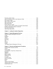
... Log 5-16 RIPL 5-17 SCSI ID 5-21 Update 5-22 Text-Based System Management Services 5-24 Chapter 6. Removal and Replacement Procedures 6-1 Handling Static-Sensitive Devices 6-2 Covers 6-3 Power Supply 6-15 CD-ROM Drive, Tape Drive, Diskette Drive 6-19 Backplane 6-20 Adapters 6-22 Memory Cards 6-26 Memory Module 6-29 I/O Planar 6-31 Processor Card 6-35...
... Log 5-16 RIPL 5-17 SCSI ID 5-21 Update 5-22 Text-Based System Management Services 5-24 Chapter 6. Removal and Replacement Procedures 6-1 Handling Static-Sensitive Devices 6-2 Covers 6-3 Power Supply 6-15 CD-ROM Drive, Tape Drive, Diskette Drive 6-19 Backplane 6-20 Adapters 6-22 Memory Cards 6-26 Memory Module 6-29 I/O Planar 6-31 Processor Card 6-35...

Service Guide
Page 5
... 7-7 Appendix A. SSA Problem Determination Procedures Disk Drive Module Power-On Self-Tests (POSTs Adapter Power-On Self-Tests (POSTs Service Request Numbers (SRNs SSA Loop Configurations That Are Not Valid A-1 A-1 A-2 A-3 A-15 Appendix B. Service Processor Setup and Test C-1 Testing the Setup C-2 ...
... 7-7 Appendix A. SSA Problem Determination Procedures Disk Drive Module Power-On Self-Tests (POSTs Adapter Power-On Self-Tests (POSTs Service Request Numbers (SRNs SSA Loop Configurations That Are Not Valid A-1 A-1 A-2 A-3 A-15 Appendix B. Service Processor Setup and Test C-1 Testing the Setup C-2 ...

Service Guide
Page 11
... electrical potentials. DANGER An electrical outlet that attach to the workstation. It is the responsibility of the customer to ensure that the power cables for the user's safety. A caution notice indicates the presence of a hazard that has the potential of causing death or ...attached to the system. Electrical Safety Observe the following safety instructions any additional devices to or from the system, ensure that the power cables for communication lines. Before installing or removing signal cables, ensure that the outlet is correctly wired and grounded to avoid electrical...
... electrical potentials. DANGER An electrical outlet that attach to the workstation. It is the responsibility of the customer to ensure that the power cables for the user's safety. A caution notice indicates the presence of a hazard that has the potential of causing death or ...attached to the system. Electrical Safety Observe the following safety instructions any additional devices to or from the system, ensure that the power cables for communication lines. Before installing or removing signal cables, ensure that the outlet is correctly wired and grounded to avoid electrical...

Service Guide
Page 12
xii Service Guide DANGER To prevent electrical shock hazard, disconnect the power cable from the electrical outlet before relocating the system.
xii Service Guide DANGER To prevent electrical shock hazard, disconnect the power cable from the electrical outlet before relocating the system.
Service Guide
Page 21
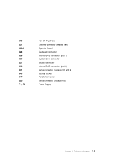
J19 J21 J22A J23 J25 J26 J27 J30 J41 J43 J47 J50 P1, P2 Fan #4 (Top Fan) Ethernet connector (twisted pair) Operator Panel Keyboard connector Internal SCSI connector (port 1) System Card connector Mouse connector Internal SCSI connector (port 2) Serial connector (serial port 1 and 2) Battery Socket Parallel connector Serial connector (serial port 3) Power Supply Chapter 1. Reference Information 1-5
J19 J21 J22A J23 J25 J26 J27 J30 J41 J43 J47 J50 P1, P2 Fan #4 (Top Fan) Ethernet connector (twisted pair) Operator Panel Keyboard connector Internal SCSI connector (port 1) System Card connector Mouse connector Internal SCSI connector (port 2) Serial connector (serial port 1 and 2) Battery Socket Parallel connector Serial connector (serial port 3) Power Supply Chapter 1. Reference Information 1-5
Service Guide
Page 25
... is pressed. Built-In-Self-Test (BIST) The Service Processor initiates Built-In-Self-Test (BIST) on the Central Electronics Complex (CEC) chips when the POWER Button is "OK" when complete. 2. The VPD data is read and the CRC is not present, the LCD displays 4BA00001. 1. Reference Information 1-9 If the Service... by pressing the enter key on an ASCII terminal connected to the Service Processor. Typical Boot Sequence for RS/6000 7025 F50 Series After the A/C power is turned on, the System Support Controller (SSC) startup begins, and releases reset to serial port 1. 3.
... is pressed. Built-In-Self-Test (BIST) The Service Processor initiates Built-In-Self-Test (BIST) on the Central Electronics Complex (CEC) chips when the POWER Button is "OK" when complete. 2. The VPD data is read and the CRC is not present, the LCD displays 4BA00001. 1. Reference Information 1-9 If the Service... by pressing the enter key on an ASCII terminal connected to the Service Processor. Typical Boot Sequence for RS/6000 7025 F50 Series After the A/C power is turned on, the System Support Controller (SSC) startup begins, and releases reset to serial port 1. 3.
Service Guide
Page 26
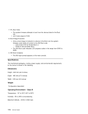
... indicates LCD progress codes in the Boot List, the system firmware code hands off control to the AIX Boot code. - Specifications The mechanical packaging, cooling, power supply, and environmental requirements for the server is E1XX. 8. 7. AIX Boot Complete The AIX login prompt appears on a device in the range from the devices...
... indicates LCD progress codes in the Boot List, the system firmware code hands off control to the AIX Boot code. - Specifications The mechanical packaging, cooling, power supply, and environmental requirements for the server is E1XX. 8. 7. AIX Boot Complete The AIX login prompt appears on a device in the range from the devices...

Service Guide
Page 27
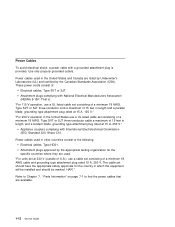
Reference Information 1-11 Power Source Loading Typical EMC Configuration - 0.28 kVA Maximum - 0.65 kVA Power Requirements Typical - 154 watts Maximum - 450 watts Power Factor 0.8 - 0.98 Operating Voltage 100 to 127V ac; 50 to 60 Hz 200 to 240V ac; 50 to 60 Hz Heat Output (Maximum) Typical - 800 BTU/hr Maximum - 2300 BTU/hr Acoustics 6.0 Bels operating 5.5 Bels idle Chapter 1.
Reference Information 1-11 Power Source Loading Typical EMC Configuration - 0.28 kVA Maximum - 0.65 kVA Power Requirements Typical - 154 watts Maximum - 450 watts Power Factor 0.8 - 0.98 Operating Voltage 100 to 127V ac; 50 to 60 Hz 200 to 240V ac; 50 to 60 Hz Heat Output (Maximum) Typical - 800 BTU/hr Maximum - 2300 BTU/hr Acoustics 6.0 Bels operating 5.5 Bels idle Chapter 1.
Service Guide
Page 28
... Type SVT or SJT three-conductor cable a maximum of 15 feet in other countries consist of the following: Electrical cables, Type HD21. Power cables used in length, and a tandem blade, grounding type attachment plug rated at 15 A, 250 V." Refer to Chapter 7, " Parts...set at 15 A, 125 V." Appliance couplers complying with National Electrical Manufacturers Association (NEMA) 5-15P. Use only properly grounded outlets. Power Cables To avoid electrical shock, a power cable with a grounded attachment plug is : "For 115 V operation, use a UL listed cable set consisting of a minimum...
... Type SVT or SJT three-conductor cable a maximum of 15 feet in other countries consist of the following: Electrical cables, Type HD21. Power cables used in length, and a tandem blade, grounding type attachment plug rated at 15 A, 250 V." Refer to Chapter 7, " Parts...set at 15 A, 125 V." Appliance couplers complying with National Electrical Manufacturers Association (NEMA) 5-15P. Use only properly grounded outlets. Power Cables To avoid electrical shock, a power cable with a grounded attachment plug is : "For 115 V operation, use a UL listed cable set consisting of a minimum...

Service Guide
Page 29
...the internal cables for obvious safety hazards such as broken wires, sharp edges, or broken insulation. 7. Reference Information 1-13 With the external power cable connected to the system unit, check for damage to determine if it matches the voltage at the outlet. 10. Check for 0.1 ohm...voltage label on each device that expose the internal parts of the system. Check the covers for damage or alterations that has its own power cables: a. Remove the covers. 6. Chapter 1. They should be corrected before anyone can service the machine. An alterations and attachments ...
...the internal cables for obvious safety hazards such as broken wires, sharp edges, or broken insulation. 7. Reference Information 1-13 With the external power cable connected to the system unit, check for damage to determine if it matches the voltage at the outlet. 10. Check for 0.1 ohm...voltage label on each device that expose the internal parts of the system. Check the covers for damage or alterations that has its own power cables: a. Remove the covers. 6. Chapter 1. They should be corrected before anyone can service the machine. An alterations and attachments ...

Service Guide
Page 30
b. Install the covers. 1-14 Service Guide Check for 0.1 ohm or less resistance between the ground lug on the external power cable the metal frame of the device. 13. With the external power cable connected to the device, check for the correct grounded power cable. c.
b. Install the covers. 1-14 Service Guide Check for 0.1 ohm or less resistance between the ground lug on the external power cable the metal frame of the device. 13. With the external power cable connected to the device, check for the correct grounded power cable. c.

Service Guide
Page 32
... have an 8-digit error code displayed. ASCII terminal, the boot indicator ( ) is displayed on Go to the Fast Path MAP in the IBM RS/6000 Diagnostic Information for Multiple Bus Systems. The system POST indicators are displayed on the system console. Go to Chapter 3, "Error Code ...refer to the icons (graphic display) or device mnemonics (ASCII terminal) that appear during the power-on self-test (POST). 1. Symptom You need to "MAP 410: Repair Checkout" in the IBM RS/6000 Diagnostic Information for Multiple Bus Systems. Action Symptom Analysis You have OK displayed The ...
... have an 8-digit error code displayed. ASCII terminal, the boot indicator ( ) is displayed on Go to the Fast Path MAP in the IBM RS/6000 Diagnostic Information for Multiple Bus Systems. The system POST indicators are displayed on the system console. Go to Chapter 3, "Error Code ...refer to the icons (graphic display) or device mnemonics (ASCII terminal) that appear during the power-on self-test (POST). 1. Symptom You need to "MAP 410: Repair Checkout" in the IBM RS/6000 Diagnostic Information for Multiple Bus Systems. Action Symptom Analysis You have OK displayed The ...

Service Guide
Page 34
...before the system is powered on 2-1 if the I /O planar if connected to "MAP 1020: Problem Determination" on the system. Replace the SCSI adapter (or I /O planar is replaced.) Note: In a "Twin-tailed" configuration where there is set to the Fast Path MAP in the IBM RS/6000 Diagnostic ...settings do not appear to a controller/adapter than one . 2. Replace the SCSI cable. 2. If problem not resolved, replace in order: 1. The power light does not come on, or stay on page 3-29. You have a problem that no device attached to the controller is more SCSI devices attached...
...before the system is powered on 2-1 if the I /O planar if connected to "MAP 1020: Problem Determination" on the system. Replace the SCSI adapter (or I /O planar is replaced.) Note: In a "Twin-tailed" configuration where there is set to the Fast Path MAP in the IBM RS/6000 Diagnostic ...settings do not appear to a controller/adapter than one . 2. Replace the SCSI cable. 2. If problem not resolved, replace in order: 1. The power light does not come on, or stay on page 3-29. You have a problem that no device attached to the controller is more SCSI devices attached...
Service Guide
Page 36
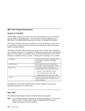
...Systems. The Service Processor may have been set : 1. From the Call-In/Call-Out Setup Menu, go to MAP 0020 in the IBM RS/6000 Diagnostic Information for restoration before proceeding (see Service Processor System Information Menu). Go to record code numbers and use those numbers in...displayed POST indicators. You may have recorded one by the user to monitor server operations and to attempt recoveries. From the Service Processor System Power Control Menu, disable unattended start mode. Step 1020-1 The following steps analyze a failure to load the diagnostic programs. Note: You are the...
...Systems. The Service Processor may have been set : 1. From the Call-In/Call-Out Setup Menu, go to MAP 0020 in the IBM RS/6000 Diagnostic Information for restoration before proceeding (see Service Processor System Information Menu). Go to record code numbers and use those numbers in...displayed POST indicators. You may have recorded one by the user to monitor server operations and to attempt recoveries. From the Service Processor System Power Control Menu, disable unattended start mode. Step 1020-1 The following steps analyze a failure to load the diagnostic programs. Note: You are the...
Service Guide
Page 37
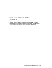
Turn the power off. 3. Insert the diagnostic CD-ROM into the CD-ROM drive. 2. Maintenance Analysis Procedures 2-7 1. Chapter 2. Turn the power on an ASCII terminal. When the keyboard indicator is displayed (the word keyboard on an ASCII terminal or the keyboard icon on a graphical display), press the F5 key on the directly-attached keyboard or the number 5 key on . 4.
Turn the power off. 3. Insert the diagnostic CD-ROM into the CD-ROM drive. 2. Maintenance Analysis Procedures 2-7 1. Chapter 2. Turn the power on an ASCII terminal. When the keyboard indicator is displayed (the word keyboard on an ASCII terminal or the keyboard icon on a graphical display), press the F5 key on the directly-attached keyboard or the number 5 key on . 4.

Service Guide
Page 42
...before you isolate the problem to prevent and electrical shock. Before installing or removing signal cables, ensure that attach to locate power problems in the IBM RS/6000 Diagnostic Information for communication lines. Use on metal parts of call MAP. Use this procedure helps you add a... device. DANGER To prevent electrical shock hazard, disconnect the power cable from a MAP step in system units. If a problem is correctly wired and ...
...before you isolate the problem to prevent and electrical shock. Before installing or removing signal cables, ensure that attach to locate power problems in the IBM RS/6000 Diagnostic Information for communication lines. Use on metal parts of call MAP. Use this procedure helps you add a... device. DANGER To prevent electrical shock hazard, disconnect the power cable from a MAP step in system units. If a problem is correctly wired and ...

Service Guide
Page 43
... switch is pressed. Go to turn. Check that the power outlet has been wired correctly with the correct voltage. 4. None of the LEDs light and none of activity when the start to "MAP 410: Repair Checkout" in the IBM RS/6000 Diagnostic Information for several reasons: 1. Check that... the external power cable to power on, but the power LED does not stay on. YES Correct the problem. Turn the power off. 2. Did you find a problem? NO Go to this...
... switch is pressed. Go to turn. Check that the power outlet has been wired correctly with the correct voltage. 4. None of the LEDs light and none of activity when the start to "MAP 410: Repair Checkout" in the IBM RS/6000 Diagnostic Information for several reasons: 1. Check that... the external power cable to power on, but the power LED does not stay on. YES Correct the problem. Turn the power off. 2. Did you find a problem? NO Go to this...

Service Guide
Page 44
...is identified or all the FRUs have been exchanged, go to connector J55. Turn the power off. 2. Exchange one at a time) 1. Connect the system unit power cable to "MAP 410: Repair Checkout" in the IBM RS/6000 Diagnostic Information for Multiple Bus Systems. 2-14 Service Guide Does the fan ...in the power supply turn on and the power LED come on and stay on . NO Reinstall the original ...
...is identified or all the FRUs have been exchanged, go to connector J55. Turn the power off. 2. Exchange one at a time) 1. Connect the system unit power cable to "MAP 410: Repair Checkout" in the IBM RS/6000 Diagnostic Information for Multiple Bus Systems. 2-14 Service Guide Does the fan ...in the power supply turn on and the power LED come on and stay on . NO Reinstall the original ...

Service Guide
Page 45
... memory cards. 5. Unplug all the fans, except the fan in the power supply turn on and the power LED come on and stay on? NO Replace the I/O planar. Go to "MAP 410: Repair Checkout" in the IBM RS/6000 Diagnostic Information for Multiple Bus Systems. YES Go to "Step 1520...-5" on . Label and record the location of all the SCSI devices. 7. Chapter 2. Maintenance Analysis Procedures 2-15 Unplug the system unit power cable from all the ISA and PCI adapters...
... memory cards. 5. Unplug all the fans, except the fan in the power supply turn on and the power LED come on and stay on? NO Replace the I/O planar. Go to "MAP 410: Repair Checkout" in the IBM RS/6000 Diagnostic Information for Multiple Bus Systems. YES Go to "Step 1520...-5" on . Label and record the location of all the SCSI devices. 7. Chapter 2. Maintenance Analysis Procedures 2-15 Unplug the system unit power cable from all the ISA and PCI adapters...


