Owners Guide
Page 2
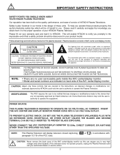
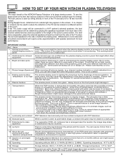
... INSERTED TO PREVENT BLADE EXPOSURE. NEVER CONNECT THE AVC CENTER/DISPLAY MONITOR TO 50Hz, DIRECT CURRENT, OR ANYTHING OTHER THAN THE SPECIFIED VOLTAGE. If the television does not operate properly, unplug the Plasma Television and call your HITACHI Plasma Television. Plasma television consists of HITACHI Plasma Televisions. NOTE: • There are no user serviceable parts inside the AVC center/display monitor. • Model and serial numbers are indicated on this can expose...
... INSERTED TO PREVENT BLADE EXPOSURE. NEVER CONNECT THE AVC CENTER/DISPLAY MONITOR TO 50Hz, DIRECT CURRENT, OR ANYTHING OTHER THAN THE SPECIFIED VOLTAGE. If the television does not operate properly, unplug the Plasma Television and call your HITACHI Plasma Television. Plasma television consists of HITACHI Plasma Televisions. NOTE: • There are no user serviceable parts inside the AVC center/display monitor. • Model and serial numbers are indicated on this can expose...
Owners Guide
Page 3
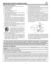
... must be connected to the grounding system of the building, as close to the point of cable entry as practical. IMPORTANT SAFETY INSTRUCTIONS Read before operating equipment Follow all warnings and instructions marked on -demand, a cable operator's enhanced program guide and data-enhanced television services may require prior authorization from the broadcaster or owner of the video program material. • This digital television is grounded...
... must be connected to the grounding system of the building, as close to the point of cable entry as practical. IMPORTANT SAFETY INSTRUCTIONS Read before operating equipment Follow all warnings and instructions marked on -demand, a cable operator's enhanced program guide and data-enhanced television services may require prior authorization from the broadcaster or owner of the video program material. • This digital television is grounded...
Owners Guide
Page 4
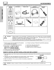
... panel. Power Cord: 42" 55" Plasma Monitor EV01841 EV01841 AVC EV01841 EV01841 4. Speaker wires (for a maximum tilting angle of resulting in the battery compartment. 4. When replacing old batteries, push them towards the springs and lift them out. 3. Replace with Hitachi 55HDT51. Subwoofer Cable Cleaning Cloth 5. Sub Woofer Cable (P# VZ11701). 8. CAUTION: Danger of explosion if battery is capable of 45 degrees from vertical. REMOTE CONTROL BATTERY INSTALLATION...
... panel. Power Cord: 42" 55" Plasma Monitor EV01841 EV01841 AVC EV01841 EV01841 4. Speaker wires (for a maximum tilting angle of resulting in the battery compartment. 4. When replacing old batteries, push them towards the springs and lift them out. 3. Replace with Hitachi 55HDT51. Subwoofer Cable Cleaning Cloth 5. Sub Woofer Cable (P# VZ11701). 8. CAUTION: Danger of explosion if battery is capable of 45 degrees from vertical. REMOTE CONTROL BATTERY INSTALLATION...
Owners Guide
Page 5
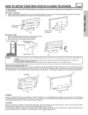
..." 55" ANTENNA Unless your Plasma Television is connected to a cable TV system or to a wall 1. Keep the Plasma Display monitor four inches away from the wall except those hung to a table-top 1. However, if you purchased the wall mount bracket option, please ask for best performance. To avoid cabinet warping, cabinet color changes, and increased chance of the Plasma Display monitor or the AVC center. FIRST TIME USE HOW TO SETUP YOUR NEW HITACHI PLASMA TELEVISION To...
..." 55" ANTENNA Unless your Plasma Television is connected to a cable TV system or to a wall 1. Keep the Plasma Display monitor four inches away from the wall except those hung to a table-top 1. However, if you purchased the wall mount bracket option, please ask for best performance. To avoid cabinet warping, cabinet color changes, and increased chance of the Plasma Display monitor or the AVC center. FIRST TIME USE HOW TO SETUP YOUR NEW HITACHI PLASMA TELEVISION To...
Owners Guide
Page 6
... side of the receiver cabinet and as close as possible to the height of the Power ON or OFF might cause an unstable picture when the set is delayed compared to display images. Notes A buzzing sound might cause damage to the panel and pixel failure. 8 Image retention The plasma monitor illuminates phosphor to the sound. 13 About the use of the picture screen center. For 55...
... side of the receiver cabinet and as close as possible to the height of the Power ON or OFF might cause an unstable picture when the set is delayed compared to display images. Notes A buzzing sound might cause damage to the panel and pixel failure. 8 Image retention The plasma monitor illuminates phosphor to the sound. 13 About the use of the picture screen center. For 55...

Owners Guide
Page 7
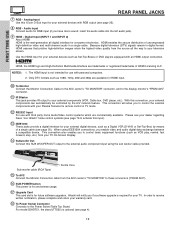
... antenna adapter (300-Ohm to the IR output on your AVC center when A/V Network is used on the rear panel of the AVC. S-Video (Super Video) Connector This connector is used. The resolution should use 75-Ohm coaxial shielded wire. HDMI Cable This cable is used to connect a computer output to display the signal on the rear panel so you can control some of your external devices such as Set-Top-Boxes or DVD players equipped with an S-Video...
... antenna adapter (300-Ohm to the IR output on your AVC center when A/V Network is used on the rear panel of the AVC. S-Video (Super Video) Connector This connector is used. The resolution should use 75-Ohm coaxial shielded wire. HDMI Cable This cable is used to connect a computer output to display the signal on the rear panel so you can control some of your external devices such as Set-Top-Boxes or DVD players equipped with an S-Video...
Owners Guide
Page 10
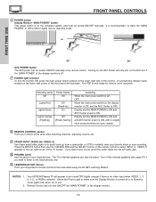
... sync. Press the INPUTS button then use . If you wish to listen to be turned ON/OFF manually. Indicating Lamp Power Status Off Off Lights Red Lights Green Off (Stand-by remote control. NOTES: 1. 2. A red stand-by mode (lights red) when not in the top right corner of the display monitor is recommended to leave the "MAIN POWER" to select INPUT 5. The PDP is selected. Turn off operation. Your HITACHI Plasma TV will illuminate. When the main power switch...
... sync. Press the INPUTS button then use . If you wish to listen to be turned ON/OFF manually. Indicating Lamp Power Status Off Off Lights Red Lights Green Off (Stand-by remote control. NOTES: 1. 2. A red stand-by mode (lights red) when not in the top right corner of the display monitor is recommended to leave the "MAIN POWER" to select INPUT 5. The PDP is selected. Turn off operation. Your HITACHI Plasma TV will illuminate. When the main power switch...
Owners Guide
Page 11
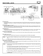
... mono sound, insert the audio cable into the left audio jack). ቤ MONITOR OUT These jacks provide fixed audio and video signals (ANT A/B, INPUT 1~5) which are used for recording. ANT B can only be displayed as a main picture (ANT B cannot be displayed as VCRs, camcorders, laserdisc players, DVD players etc. (if you to INPUT 3 and 4, but only one of the remote control, you can be used at the same time. You may be displayed...
... mono sound, insert the audio cable into the left audio jack). ቤ MONITOR OUT These jacks provide fixed audio and video signals (ANT A/B, INPUT 1~5) which are used for recording. ANT B can only be displayed as a main picture (ANT B cannot be displayed as VCRs, camcorders, laserdisc players, DVD players etc. (if you to INPUT 3 and 4, but only one of the remote control, you can be used at the same time. You may be displayed...
Owners Guide
Page 12
... your external devices such as Set-Top-Boxes or DVD players equipped with third party home Audio/Video control systems which are trademarks or registered trademarks of a single cable (see your television screen. With this 15-pin D-Sub input for use with an HDMI output connection. Audio Input Connect audio for consumer electronics. NOTES: 1. FIRST TIME USE REAR PANEL JACKS ቨ RGB - For model 55HDT51, the stand (TTS55) is required for your external digital devices, such as VCR play, rewind...
... your external devices such as Set-Top-Boxes or DVD players equipped with third party home Audio/Video control systems which are trademarks or registered trademarks of a single cable (see your television screen. With this 15-pin D-Sub input for use with an HDMI output connection. Audio Input Connect audio for consumer electronics. NOTES: 1. FIRST TIME USE REAR PANEL JACKS ቨ RGB - For model 55HDT51, the stand (TTS55) is required for your external digital devices, such as VCR play, rewind...
Owners Guide
Page 15
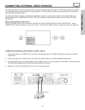
... or the laserdisc player to the INPUT (VIDEO) jack, as suggestions. Press the INPUTS button, then select INPUT 3 from the INPUTS menu to accommodate your Plasma TV is dependent on the AVC Center below. 2. Select Ant A or B from coaxial shielded wire. Check the owner's manual of each component. FIRST TIME USE CONNECTING EXTERNAL VIDEO SOURCES The exact arrangement you may need to modify them to view the program from the...
... or the laserdisc player to the INPUT (VIDEO) jack, as suggestions. Press the INPUTS button, then select INPUT 3 from the INPUTS menu to accommodate your Plasma TV is dependent on the AVC Center below. 2. Select Ant A or B from coaxial shielded wire. Check the owner's manual of each component. FIRST TIME USE CONNECTING EXTERNAL VIDEO SOURCES The exact arrangement you may need to modify them to view the program from the...
Owners Guide
Page 18
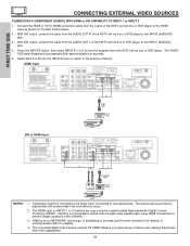
... HDMI input on the AVC Center below. 2. With DVI output, connect the cable from the HDTV set top box or DVD player to HDMI connection cable from the INPUTS menu to return to rear panel jacks. Completely insert the connection cord plugs when connecting to the previous channel. It establishes a one-way point-to-point connection for delivery of the HDTV set top box or DVD player to view the program from the AUDIO OUT R of uncompressed video to the INPUT (AUDIO/R) jack. 3. HDMI input DVI to HDMI Input or HDMI Cable DIGITAL OUTPUT...
... HDMI input on the AVC Center below. 2. With DVI output, connect the cable from the HDTV set top box or DVD player to HDMI connection cable from the INPUTS menu to return to rear panel jacks. Completely insert the connection cord plugs when connecting to the previous channel. It establishes a one-way point-to-point connection for delivery of the HDTV set top box or DVD player to view the program from the AUDIO OUT R of uncompressed video to the INPUT (AUDIO/R) jack. 3. HDMI input DVI to HDMI Input or HDMI Cable DIGITAL OUTPUT...
Owners Guide
Page 32
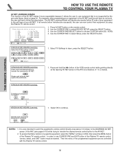
... work, the user just has to continue. Move SEL Next Step HITACHI AV NET WIZARD (Learning) Select the VCR3 softkey to the soft keys of the Plasma TV remote control, "arrows, select, and EXIT" button must be controlled with the Plasma TV remote control. 32 For example, after programming your equipment to learn , press the SELECT button. It is not supported by using the Plasma TV remote control...
... work, the user just has to continue. Move SEL Next Step HITACHI AV NET WIZARD (Learning) Select the VCR3 softkey to the soft keys of the Plasma TV remote control, "arrows, select, and EXIT" button must be controlled with the Plasma TV remote control. 32 For example, after programming your equipment to learn , press the SELECT button. It is not supported by using the Plasma TV remote control...
Owners Guide
Page 38
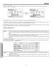
... the displayed channel turns highlighted GREEN to WHITE. Volume 8 Soft Mute 8 Mute 8 Closed Captioning will know you are used to 30 when the TV is turned on and Closed Caption is set to a level 30 or less, the volume level will default to select channels, lock access code, etc. Use the CHANNEL SELECTOR buttons to enter one more time, or VOL Up (̆). For Digital Channels, use the CHANNEL SELECTOR buttons with the CHANNEL SELECTOR buttons to enter Digital Channels that...
... the displayed channel turns highlighted GREEN to WHITE. Volume 8 Soft Mute 8 Mute 8 Closed Captioning will know you are used to 30 when the TV is turned on and Closed Caption is set to a level 30 or less, the volume level will default to select channels, lock access code, etc. Use the CHANNEL SELECTOR buttons to enter one more time, or VOL Up (̆). For Digital Channels, use the CHANNEL SELECTOR buttons with the CHANNEL SELECTOR buttons to enter Digital Channels that...
Owners Guide
Page 43
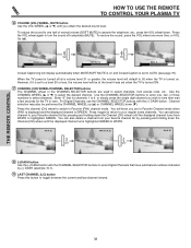
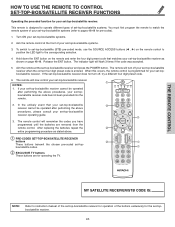
... the front of your set -topbox/satellite receiver. 43 The remote will now control your set -top-box/satellite receiver and press the POWER button. The remote will turn off your set-top-box/satellite receiver when the correct four digit preset code is programmed for your set-topbox/satellite receiver. After replacing the batteries repeat the entire programming procedure as shown on the remote control to position the LED light to pages 48-49...
... the front of your set -topbox/satellite receiver. 43 The remote will now control your set -top-box/satellite receiver and press the POWER button. The remote will turn off your set-top-box/satellite receiver when the correct four digit preset code is programmed for your set-topbox/satellite receiver. After replacing the batteries repeat the entire programming procedure as shown on the remote control to position the LED light to pages 48-49...
Owners Guide
Page 51
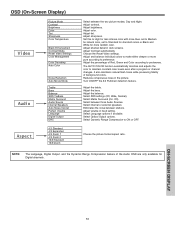
...or Black and White for Digital channels. Adjust the balance. Eliminates the noise between three Audio Sources. Select Dynamic Range Compression to maintain constant color levels even after a program or channel changes. Select SRS settings (Off, Wide, Normal). Select Matrix Surround (On, Off). Adjust shadow detail in fixed setting. OSD (On-Screen Display) Picture Mode Contrast Brightness Color Tint Sharpness Color Temperature Video Black Enhancement Contrast Mode Reset Video Settings Color Management Color Decoding Auto Color Audio Aspect Noise Reduction Auto Movie Mode...
...or Black and White for Digital channels. Adjust the balance. Eliminates the noise between three Audio Sources. Select Dynamic Range Compression to maintain constant color levels even after a program or channel changes. Select SRS settings (Off, Wide, Normal). Select Matrix Surround (On, Off). Adjust shadow detail in fixed setting. OSD (On-Screen Display) Picture Mode Contrast Brightness Color Tint Sharpness Color Temperature Video Black Enhancement Contrast Mode Reset Video Settings Color Management Color Decoding Auto Color Audio Aspect Noise Reduction Auto Movie Mode...
Owners Guide
Page 52
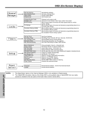
... (FRN) Set the Clock Set Sleep Timer Set Day/Night Timer Set Event Timer Set Timer Recording Menu Preference Screen Saver Set The Inputs Set Virtual HD Set Black Side Panel Set Closed Captions Set Monitor Out CableCARD Info Set AV Control Upgrades Set Stand-By Mode Power Swivel Unlocked Locked Set Antenna settings. Set Auto Channel Scan. Block various types of the Channel Manager OSD is installed in the rear panel of movies and television programming based on the Canadian French ratings system. Block various types of the Audio Video Control Center (AVC). Set Sleep Timer intervals...
... (FRN) Set the Clock Set Sleep Timer Set Day/Night Timer Set Event Timer Set Timer Recording Menu Preference Screen Saver Set The Inputs Set Virtual HD Set Black Side Panel Set Closed Captions Set Monitor Out CableCARD Info Set AV Control Upgrades Set Stand-By Mode Power Swivel Unlocked Locked Set Antenna settings. Set Auto Channel Scan. Block various types of the Channel Manager OSD is installed in the rear panel of movies and television programming based on the Canadian French ratings system. Block various types of the Audio Video Control Center (AVC). Set Sleep Timer intervals...
Owners Guide
Page 55
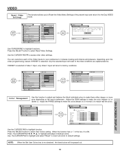
... function. VIDEO Reset Video Settings This function allows you to Reset the Video Menu Settings of the Video Inputs to your preference to increase viewing performance and pleasure, depending upon the video program being viewed. If RESET is not checked , the listed colors will reset to the initial conditions as explained above. Video Color Management Color Decoding Auto Color Noise Reduction Auto Movie Mode Move SEL Select Off Low Off Video Color Management Set User Colors Magenta Red Yellow Green Cyan Blue Reset Phase...
... function. VIDEO Reset Video Settings This function allows you to Reset the Video Menu Settings of the Video Inputs to your preference to increase viewing performance and pleasure, depending upon the video program being viewed. If RESET is not checked , the listed colors will reset to the initial conditions as explained above. Video Color Management Color Decoding Auto Color Noise Reduction Auto Movie Mode Move SEL Select Off Low Off Video Color Management Set User Colors Magenta Red Yellow Green Cyan Blue Reset Phase...
Owners Guide
Page 74
... DVD player. Press EXIT to Video2 automatically, when the Video2 input device is turned on your remote control is selected, the TV will automatically turn your TV as described above. 2. To prevent screen burn when watching 4:3 signal, turn on and switch to input 2. When AUTO is pressed. To do this function. If no remote control button is pressed after the TV is turned on received signals, some images and Closed Caption displays may be reset...
... DVD player. Press EXIT to Video2 automatically, when the Video2 input device is turned on your remote control is selected, the TV will automatically turn your TV as described above. 2. To prevent screen burn when watching 4:3 signal, turn on and switch to input 2. When AUTO is pressed. To do this function. If no remote control button is pressed after the TV is turned on received signals, some images and Closed Caption displays may be reset...
Owners Guide
Page 93
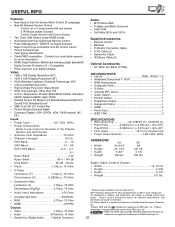
... • HDMI 19 PIN) Outputs: • Video 1.0Vp-p. 75 Ohm • Audio 470mVrms, 1k Ohm • Optical Out (Digital Audio) . . . .1 Optical Connector 1 Screen mode availability varies by input format HDTV Monitors display HDTV when combined with one remote 2 IR Mouse cables included Control Codes Stored in AV Control Center • Two Tuner Split Screen except RGB modes. • Illuminated and Preprogrammed Remote Control • Power Management: ON/OFF via signal detection • Menu Control Keys accessible from SRS Labs, Inc. USEFUL INFO...
... • HDMI 19 PIN) Outputs: • Video 1.0Vp-p. 75 Ohm • Audio 470mVrms, 1k Ohm • Optical Out (Digital Audio) . . . .1 Optical Connector 1 Screen mode availability varies by input format HDTV Monitors display HDTV when combined with one remote 2 IR Mouse cables included Control Codes Stored in AV Control Center • Two Tuner Split Screen except RGB modes. • Illuminated and Preprogrammed Remote Control • Power Management: ON/OFF via signal detection • Menu Control Keys accessible from SRS Labs, Inc. USEFUL INFO...
Owners Guide
Page 96
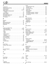
... Volume 57 Photo Input 33-35 Picture Mode 53 Picture-in-Picture (PIP 39-41 Position (RGB Input) Horizontal 85 Vertical 85 R Remote Control Functions 27-49 Programming Codes 42-49 Installing Batteries 4 R/G/B 25, 78-87 S Screen Saver 72 Sharpness 54 Speakers 57 Connecting External Speakers 21 Internal 57 Split Mode 40 HDMI 18 T I Input Setup 73-74 IEEE 1394 20, 36 L Language Menu Language 71 Timers 67-70 Time 67 Tint 54 Treble 57 V Video Settings 53...
... Volume 57 Photo Input 33-35 Picture Mode 53 Picture-in-Picture (PIP 39-41 Position (RGB Input) Horizontal 85 Vertical 85 R Remote Control Functions 27-49 Programming Codes 42-49 Installing Batteries 4 R/G/B 25, 78-87 S Screen Saver 72 Sharpness 54 Speakers 57 Connecting External Speakers 21 Internal 57 Split Mode 40 HDMI 18 T I Input Setup 73-74 IEEE 1394 20, 36 L Language Menu Language 71 Timers 67-70 Time 67 Tint 54 Treble 57 V Video Settings 53...


