Owners Guide
Page 1
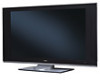
has determined that this product meets the ENERGY STAR® guidelines for 42HDT51, 55HDT51 IMPORTANT SAFETY INSTRUCTIONS 2-3 FIRST TIME USE ...4-26 THE REMOTE CONTROL 27-49 ON-SCREEN DISPLAY...50-77 USING THE RGB INPUT OF THE PLASMA TV 78-87 CARE OF YOUR HITACHI PLASMA TV & REMOTE CONTROL 88 RECEPTION PROBLEMS ...89 USEFUL INFORMATION/INDEX 90-98 As an ENERGY STAR® Partner, Hitachi, Ltd. PLASMA TELEVISION AVC (Audio Video Control Center) & Plasma Display Monitor Operating Guide for energy efficiency.
has determined that this product meets the ENERGY STAR® guidelines for 42HDT51, 55HDT51 IMPORTANT SAFETY INSTRUCTIONS 2-3 FIRST TIME USE ...4-26 THE REMOTE CONTROL 27-49 ON-SCREEN DISPLAY...50-77 USING THE RGB INPUT OF THE PLASMA TV 78-87 CARE OF YOUR HITACHI PLASMA TV & REMOTE CONTROL 88 RECEPTION PROBLEMS ...89 USEFUL INFORMATION/INDEX 90-98 As an ENERGY STAR® Partner, Hitachi, Ltd. PLASMA TELEVISION AVC (Audio Video Control Center) & Plasma Display Monitor Operating Guide for energy efficiency.
Owners Guide
Page 2
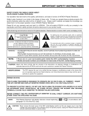
... of your product model. NOTE: • There are no user serviceable parts inside the AVC center/display monitor. • Model and serial numbers are not expressly approved by HITACHI could void the user's authority to persons. This will be discovered in the instructions, as... CAUTION: Never remove the back cover of these products properly, this section illustrates safety tips which will enable HITACHI to operate the equipment. NEVER CONNECT THE AVC CENTER/DISPLAY MONITOR TO 50Hz, DIRECT CURRENT, OR ANYTHING OTHER THAN THE SPECIFIED VOLTAGE. WARNING: •TO ...
... of your product model. NOTE: • There are no user serviceable parts inside the AVC center/display monitor. • Model and serial numbers are not expressly approved by HITACHI could void the user's authority to persons. This will be discovered in the instructions, as... CAUTION: Never remove the back cover of these products properly, this section illustrates safety tips which will enable HITACHI to operate the equipment. NEVER CONNECT THE AVC CENTER/DISPLAY MONITOR TO 50Hz, DIRECT CURRENT, OR ANYTHING OTHER THAN THE SPECIFIED VOLTAGE. WARNING: •TO ...
Owners Guide
Page 4
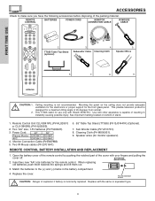
... front glass panel. When replacing old batteries, push them towards the springs and lift them out. 3. Replace with Hitachi 55HDT51. ACCESSORIES Check to remove. Mounting the panel on bottom of the cover with other apparatus is not recommended. Remote Control... by pushing the notched part of stand. 1. Speaker Wires 6. 7. 8. 9. 1. Power Cord: 42" 55" Plasma Monitor EV01841 EV01841 AVC EV01841 EV01841 4. Sub Woofer Cable (P# VZ11701). 8. BOTTOM VIEW (Remote Control) 2. REMOTE CONTROL BATTERIES POWER CORD MONITOR CONNECTION CABLE IR MOUSE...
... front glass panel. When replacing old batteries, push them towards the springs and lift them out. 3. Replace with Hitachi 55HDT51. ACCESSORIES Check to remove. Mounting the panel on bottom of the cover with other apparatus is not recommended. Remote Control... by pushing the notched part of stand. 1. Speaker Wires 6. 7. 8. 9. 1. Power Cord: 42" 55" Plasma Monitor EV01841 EV01841 AVC EV01841 EV01841 4. Sub Woofer Cable (P# VZ11701). 8. BOTTOM VIEW (Remote Control) 2. REMOTE CONTROL BATTERIES POWER CORD MONITOR CONNECTION CABLE IR MOUSE...
Owners Guide
Page 5
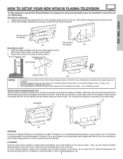
...area where sunlight or bright indoor illumination will not fall directly on the Plasma Display monitor. FIRST TIME USE HOW TO SETUP YOUR NEW HITACHI PLASMA TELEVISION To take measures to prevent the Plasma Display from tipping over and prevent possible injury it should be sufficient. Wood screw ... warping, cabinet color changes, and increased chance of the Plasma Display monitor or the AVC center. Securing to mount the unit in position. The plasma television has two AC cords, one on the AVC center and the other on the picture screen. Do not block the ventilation holes of...
...area where sunlight or bright indoor illumination will not fall directly on the Plasma Display monitor. FIRST TIME USE HOW TO SETUP YOUR NEW HITACHI PLASMA TELEVISION To take measures to prevent the Plasma Display from tipping over and prevent possible injury it should be sufficient. Wood screw ... warping, cabinet color changes, and increased chance of the Plasma Display monitor or the AVC center. Securing to mount the unit in position. The plasma television has two AC cords, one on the AVC center and the other on the picture screen. Do not block the ventilation holes of...

Owners Guide
Page 7
... Twin Lead Connector This outdoor antenna cable must place the IR mouse in place of the Display Monitor. Below are illustrations and names of the AVC Center (ex. The resolution should use 75-Ohm coaxial shielded wire. Phono Connector Used on all standard video and audio cables which connect to... (300-Ohm to display the signal on camcorders, VCRs and laserdisc players with an S-Video feature in front of the corresponding IR window of the AVC. AUDIO OUT 3.8mm STEREO MINI-PLUG 2 RCA TYPE PLUGS Stereo Cable (3.5 mm plug to 3.5 mm plug) This cable is used to connect your ...
... Twin Lead Connector This outdoor antenna cable must place the IR mouse in place of the Display Monitor. Below are illustrations and names of the AVC Center (ex. The resolution should use 75-Ohm coaxial shielded wire. Phono Connector Used on all standard video and audio cables which connect to... (300-Ohm to display the signal on camcorders, VCRs and laserdisc players with an S-Video feature in front of the corresponding IR window of the AVC. AUDIO OUT 3.8mm STEREO MINI-PLUG 2 RCA TYPE PLUGS Stereo Cable (3.5 mm plug to 3.5 mm plug) This cable is used to connect your ...
Owners Guide
Page 9
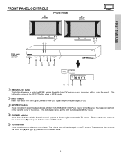
..." DISPLAY MONITOR FRONT VIEW 55" DISPLAY MONITOR ቭቩ STANDBY (RED) ON (GREEN) MAIN POWER ቩቧ ቨ STANDBY (RED) ON (GREEN) ቩቧ ቨ (AVC) AUDIO VIDEO CONTROL CENTER POWER STANDBY (RED) ON (GREEN) VOL- VOL+ CH-
..." DISPLAY MONITOR FRONT VIEW 55" DISPLAY MONITOR ቭቩ STANDBY (RED) ON (GREEN) MAIN POWER ቩቧ ቨ STANDBY (RED) ON (GREEN) ቩቧ ቨ (AVC) AUDIO VIDEO CONTROL CENTER POWER STANDBY (RED) ON (GREEN) VOL- VOL+ CH-
Owners Guide
Page 10
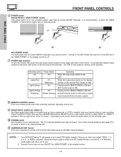
... manually or by mode (lights red) when not in the top right corner of the TV screen. Press the INPUTS button then use . Your HITACHI Plasma TV will illuminate. Indicating Lamp Power Status Off Off Lights Red Lights Green Off (Stand-by mode. Display monitor MAIN POWER is ON and... and AVC Center power is ON, with no signal input except antenna (no video input when VIDEO: 1, 2, 3, 4, 5, or RGB is selected. Turn off . ቨ POWER ...
... manually or by mode (lights red) when not in the top right corner of the TV screen. Press the INPUTS button then use . Your HITACHI Plasma TV will illuminate. Indicating Lamp Power Status Off Off Lights Red Lights Green Off (Stand-by mode. Display monitor MAIN POWER is ON and... and AVC Center power is ON, with no signal input except antenna (no video input when VIDEO: 1, 2, 3, 4, 5, or RGB is selected. Turn off . ቨ POWER ...
Owners Guide
Page 11
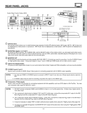
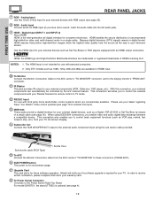
...and HDMI inputs. 11 NOTES: 1. In this case, connect the components B-Y output to the AVC Box's PB input and the components R-Y output to the AVC Box's PR input. 4. FIRST TIME USE REAR PANEL JACKS Audio Video Control Center (AVC) ቢ ቯ ቦ ቨቪ ቫ ትታ ብ &#...R-Y. Your component outputs may be labeled Y-CBCR. In this case, connect the component CB output to the AVC Box's PB input and the component CR output to the AVC Box's PR input. 3. You may use composite video signal for connecting equipment with S-VIDEO output capability. ...
...and HDMI inputs. 11 NOTES: 1. In this case, connect the components B-Y output to the AVC Box's PB input and the components R-Y output to the AVC Box's PR input. 4. FIRST TIME USE REAR PANEL JACKS Audio Video Control Center (AVC) ቢ ቯ ቦ ቨቪ ቫ ትታ ብ &#...R-Y. Your component outputs may be labeled Y-CBCR. In this case, connect the component CB output to the AVC Box's PB input and the component CR output to the AVC Box's PR input. 3. You may use composite video signal for connecting equipment with S-VIDEO output capability. ...
Owners Guide
Page 12
...Multimedia Interface are commercially available. Ferrite Core Sub-woofer cable (RCA Type) ቱ To AVC Connect the Monitor Connection cable from your TV On-Screen Display. ተ Subwoofer Out Connect... of a single cable (see page 25). ቩ RGB - Hitachi will allow you to control the external components with your warranty card. ቴ To Power...jacks provide a digital interface for your external components (VCR, Cable box, DVD player, etc.). For model 55HDT51, the stand (TTS55) is required for your external devices such as a Digital VCR (D-VHS or Set-Top...
...Multimedia Interface are commercially available. Ferrite Core Sub-woofer cable (RCA Type) ቱ To AVC Connect the Monitor Connection cable from your TV On-Screen Display. ተ Subwoofer Out Connect... of a single cable (see page 25). ቩ RGB - Hitachi will allow you to control the external components with your warranty card. ቴ To Power...jacks provide a digital interface for your external components (VCR, Cable box, DVD player, etc.). For model 55HDT51, the stand (TTS55) is required for your external devices such as a Digital VCR (D-VHS or Set-Top...

Owners Guide
Page 13
... A terminal of Deployment (POD) module). Acquiring Data. Please see pages 63-64 and 76 for viewing. Connect a coaxial cable to return Please take note of AVC ICNaSEblRTeTHICSAENRDD If the CableCARD is installed, wait until the second screen below will appear if a channel is not authorized for additional CableCARD information. 13 CableCARD...
... A terminal of Deployment (POD) module). Acquiring Data. Please see pages 63-64 and 76 for viewing. Connect a coaxial cable to return Please take note of AVC ICNaSEblRTeTHICSAENRDD If the CableCARD is installed, wait until the second screen below will appear if a channel is not authorized for additional CableCARD information. 13 CableCARD...
Owners Guide
Page 14
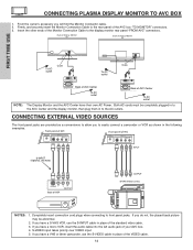
...following examples: Front panel of AVC Front panel of AVC PHONES S-VIDEO INPUT 5 AUDIO VIDEO L/(MONO) R PHONES S-VIDEO INPUT 5 AUDIO VIDEO L/(MONO) R NOTES: 1. Insert the other ends of Display Monitor 55" To AC outlet Core To AC outlet Core NOTE: Please use HITACHI specified cable. Back of ...Display Monitor 42" Back of the Monitor Connection Cable to front panel jacks. TO MONITOR AC IN Back of AVC Center TruBass SRS and symbol are trademarks of SRS Labs, Inc. ...
...following examples: Front panel of AVC Front panel of AVC PHONES S-VIDEO INPUT 5 AUDIO VIDEO L/(MONO) R PHONES S-VIDEO INPUT 5 AUDIO VIDEO L/(MONO) R NOTES: 1. Insert the other ends of Display Monitor 55" To AC outlet Core To AC outlet Core NOTE: Please use HITACHI specified cable. Back of ...Display Monitor 42" Back of the Monitor Connection Cable to front panel jacks. TO MONITOR AC IN Back of AVC Center TruBass SRS and symbol are trademarks of SRS Labs, Inc. ...
Owners Guide
Page 15
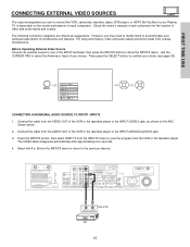
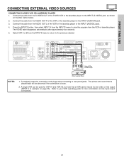
... them to accommodate your choice. Check the owner's manual of components and features. Use the CURSOR PAD to your Plasma TV is dependent on the AVC Center below. 2. Select Ant A or B from the AUDIO OUT of video and audio inputs and outputs. However, you use to connect the VCR, camcorder, laserdisc...
... them to accommodate your choice. Check the owner's manual of components and features. Use the CURSOR PAD to your Plasma TV is dependent on the AVC Center below. 2. Select Ant A or B from the AUDIO OUT of video and audio inputs and outputs. However, you use to connect the VCR, camcorder, laserdisc...
Owners Guide
Page 16
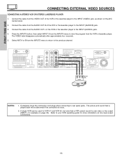
... laserdisc player to your VCR operating guide for VCR #1 and VCR #2, but note that is played back will be used for more information on the AVC Center below. 2. Completely insert the connection cord plugs when connecting to view the program from the VCR or laserdisc player. Press the INPUTS button, then...
... laserdisc player to your VCR operating guide for VCR #1 and VCR #2, but note that is played back will be used for more information on the AVC Center below. 2. Completely insert the connection cord plugs when connecting to view the program from the VCR or laserdisc player. Press the INPUTS button, then...
Owners Guide
Page 17
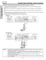
... a VCR cannot record its own video or line output (INPUT: 4 in example on page 25). A single VCR can be used for more information on the AVC Center below. 2. Press the INPUTS button, then select INPUT 4 from the INPUTS menu to view the program from the AUDIO OUT L of the S-VHS VCR...
... a VCR cannot record its own video or line output (INPUT: 4 in example on page 25). A single VCR can be used for more information on the AVC Center below. 2. Press the INPUTS button, then select INPUT 4 from the INPUTS menu to view the program from the AUDIO OUT L of the S-VHS VCR...
Owners Guide
Page 18
... to HDMI Cable LR OUTPUT DIGITAL OUTPUT Back of uncompressed video to -point connection for delivery of D-VHS NOTES: D-VHS 1. The HDMI input on the AVC Center below. 2. It establishes a one-way point-to a display. 4. The connected digital output device controls the HDMI interface so proper set top box or DVD...
... to HDMI Cable LR OUTPUT DIGITAL OUTPUT Back of uncompressed video to -point connection for delivery of D-VHS NOTES: D-VHS 1. The HDMI input on the AVC Center below. 2. It establishes a one-way point-to a display. 4. The connected digital output device controls the HDMI interface so proper set top box or DVD...

Owners Guide
Page 19
... menu to the INPUT (AUDIO/L) jack. 6. Completely insert the connection cord plugs when connecting to the previous channel. See page 26 for tips on the AVC Center below. 2. Connect the cable from the CR/PR OUT or R-Y OUT of the Laserdisc/DVD player or HDTV set top box to view the...
... menu to the INPUT (AUDIO/L) jack. 6. Completely insert the connection cord plugs when connecting to the previous channel. See page 26 for tips on the AVC Center below. 2. Connect the cable from the CR/PR OUT or R-Y OUT of the Laserdisc/DVD player or HDTV set top box to view the...
Owners Guide
Page 20
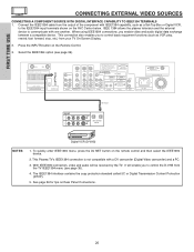
... EXTERNAL VIDEO SOURCES CONNECTING A COMPONENT SOURCE WITH DIGITAL INTERFACE CAPABILITY TO IEEE1394 TERMINALS 1. To quickly enter IEEE1394 menu, press the AV NET button on the AVC Center below. Connect the IEEE1394 cable from the output of the component with a DV camcorder (Digital Video camcorder) and a PC. 3. Select the IEEE1394 option (see...
... EXTERNAL VIDEO SOURCES CONNECTING A COMPONENT SOURCE WITH DIGITAL INTERFACE CAPABILITY TO IEEE1394 TERMINALS 1. To quickly enter IEEE1394 menu, press the AV NET button on the AVC Center below. Connect the IEEE1394 cable from the output of the component with a DV camcorder (Digital Video camcorder) and a PC. 3. Select the IEEE1394 option (see...
Owners Guide
Page 21
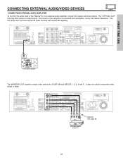
.... R L V S-VIDEO INPUT VCR or other external components Optional, See page 26 21 The Volume of the amplifier is a fixed output. The "OPTICAL OUT" from the AVC center is controlled by the amplifier, not by the Plasma Television. FIRST TIME USE OPTICAL INPUT Stereo System Amplifier The MONITOR OUT terminal outputs video...
.... R L V S-VIDEO INPUT VCR or other external components Optional, See page 26 21 The Volume of the amplifier is a fixed output. The "OPTICAL OUT" from the AVC center is controlled by the amplifier, not by the Plasma Television. FIRST TIME USE OPTICAL INPUT Stereo System Amplifier The MONITOR OUT terminal outputs video...
Owners Guide
Page 22
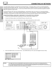
... R L DVD Player 4. Once this is equipped with up to 2 external Audio/Video components. The Plasma Television AVC Center has 2 IR BLASTER jacks. Please see the following example of an AV Network setup between your Hitachi Plasma TV Remote Control. CONNECTING EXTERNAL AUDIO/VIDEO COMPONENTS TO IR BLASTER FOR AV NETWORK 1. Place the...
... R L DVD Player 4. Once this is equipped with up to 2 external Audio/Video components. The Plasma Television AVC Center has 2 IR BLASTER jacks. Please see the following example of an AV Network setup between your Hitachi Plasma TV Remote Control. CONNECTING EXTERNAL AUDIO/VIDEO COMPONENTS TO IR BLASTER FOR AV NETWORK 1. Place the...
Owners Guide
Page 26
...), connect it is of S-VIDEO type. • When using a DVI or HDMI input from a Set-Top-Box, it to the left audio jack on the AVC Center. • Refer to the operating guide of the standard video connection if your device has this feature. • If your VCR operating guide for...
...), connect it is of S-VIDEO type. • When using a DVI or HDMI input from a Set-Top-Box, it to the left audio jack on the AVC Center. • Refer to the operating guide of the standard video connection if your device has this feature. • If your VCR operating guide for...


