Owners Guide
Page 1
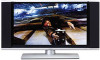
... CONTROL 24-39 ON-SCREEN DISPLAY USING THE RGB INPUT OF THE PLASMA TV 40-63 64-74 USEFUL INFORMATION INDEX 75-82 PLASMA TELEVISION AVC (Audio/Video Control Center) & Plasma Display Monitor 32HDT20 42HDT20 OPERATING GUIDE Video Audio Ch.
... CONTROL 24-39 ON-SCREEN DISPLAY USING THE RGB INPUT OF THE PLASMA TV 40-63 64-74 USEFUL INFORMATION INDEX 75-82 PLASMA TELEVISION AVC (Audio/Video Control Center) & Plasma Display Monitor 32HDT20 42HDT20 OPERATING GUIDE Video Audio Ch.
Owners Guide
Page 2
...will be notified that any changes or modifications made to operate the Plasma Television. Please fill out your HITACHI Plasma Television. Plasma television consists of the AVC center/display monitor. The lightning flash with arrowhead symbol, within an equilateral triangle, is intended to alert ...an equilateral triangle, is intended to alert the user to operate the equipment. NOTE: This Plasma Television will enable HITACHI to notify you . INSERT THE AVC CENTER AND DISPLAY MONITOR POWER CORD INTO A 120 VOLT 60Hz OUTLET. To help you to persons. Follow all warnings and...
...will be notified that any changes or modifications made to operate the Plasma Television. Please fill out your HITACHI Plasma Television. Plasma television consists of the AVC center/display monitor. The lightning flash with arrowhead symbol, within an equilateral triangle, is intended to alert ...an equilateral triangle, is intended to alert the user to operate the equipment. NOTE: This Plasma Television will enable HITACHI to notify you . INSERT THE AVC CENTER AND DISPLAY MONITOR POWER CORD INTO A 120 VOLT 60Hz OUTLET. To help you to persons. Follow all warnings and...
Owners Guide
Page 6
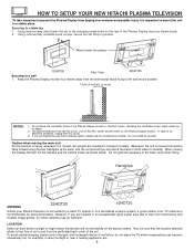
...the Display Monitor, lift the handles and the bottom frame as shown below . Handgrips ANTENNA 32HDT20 42HDT20 Unless your Plasma Television is connected to a cable TV system or to a centralized antenna system...example, in a stable place. The plasma television has two AC cords, one on the AVC center and the other on the picture screen. Using commercially available wood screws, secure the set ...rear of the Plasma Display stand as shown below . 2. HOW TO SETUP YOUR NEW HITACHI PLASMA TELEVISION To take measures to prevent the Plasma Display from tipping over and prevent ...
...the Display Monitor, lift the handles and the bottom frame as shown below . Handgrips ANTENNA 32HDT20 42HDT20 Unless your Plasma Television is connected to a cable TV system or to a centralized antenna system...example, in a stable place. The plasma television has two AC cords, one on the AVC center and the other on the picture screen. Using commercially available wood screws, secure the set ...rear of the Plasma Display stand as shown below . 2. HOW TO SETUP YOUR NEW HITACHI PLASMA TELEVISION To take measures to prevent the Plasma Display from tipping over and prevent ...
Owners Guide
Page 8
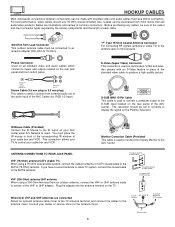
... panel and front control panel. For best performance, video cables should be set to correctly to the antenna mixer. This connection allows your AVC center when A/V Network is used . To second antenna or cable system To outdoor VHF or UHF antenna When both VHF and UHF antennas are...connector is used on the Plasma Television. Cables can be made with an S-Video feature in front of the corresponding IR window of the AVC Center. Monitor Conection Cable (Provided) This cable is used to connect the Display Monitor to the D-SUB input located on the television. ANTENNA ...
... panel and front control panel. For best performance, video cables should be set to correctly to the antenna mixer. This connection allows your AVC center when A/V Network is used . To second antenna or cable system To outdoor VHF or UHF antenna When both VHF and UHF antennas are...connector is used on the Plasma Television. Cables can be made with an S-Video feature in front of the corresponding IR window of the AVC Center. Monitor Conection Cable (Provided) This cable is used to connect the Display Monitor to the D-SUB input located on the television. ANTENNA ...
Owners Guide
Page 10
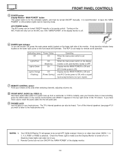
...stand-by mode. The TV's internal speakers can also be turned OFF (lights orange) if there is no sync. Your HITACHI Plasma TV will illuminate. AVC POWER button The AVC power can not turn ON/OFF the "MAIN POWER" of the TV screen. Remote Control can be turned ON/OFF manually...antenna (no video input when VIDEO: 1, 2, 3, 4, 5, RGB1 or RGB2 is selected. press the VID5 button on the display monitor is ON, and the AVC Center is OFF. A red stand-by ) On Lights Orange Off (Flashing) (Power Saving) Operating When the main power switch is set OFF. Turn off operation. ...
...stand-by mode. The TV's internal speakers can also be turned OFF (lights orange) if there is no sync. Your HITACHI Plasma TV will illuminate. AVC POWER button The AVC power can not turn ON/OFF the "MAIN POWER" of the TV screen. Remote Control can be turned ON/OFF manually...antenna (no video input when VIDEO: 1, 2, 3, 4, 5, RGB1 or RGB2 is selected. press the VID5 button on the display monitor is ON, and the AVC Center is OFF. A red stand-by ) On Lights Orange Off (Flashing) (Power Saving) Operating When the main power switch is set OFF. Turn off operation. ...
Owners Guide
Page 11
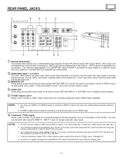
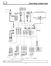
... recording. INPUT 1 does not accept composite video signal. NOTES: 1. REAR PANEL JACKS ቢ ቦ ቧ ቨ ቪ REAR PANEL OF THE AVC CENTER ANT A TO CONVERTER ANT B MONITOR OUT S-VIDEO INPUT 4 S-VIDEO INPUT 3 S-VIDEO VIDEO VIDEO VIDEO (MONO) (MONO) (MONO) L L L R ... and 2 provide Y-PBPR jacks for connecting equipment with S-VIDEO output capability. You may be the component CR output to the AVC Box's PB input 3. case, connect the components B-Y output to the AlaVbCelBedoxY's-CPBRCiRn.puItn. In this capability, such as a...
... recording. INPUT 1 does not accept composite video signal. NOTES: 1. REAR PANEL JACKS ቢ ቦ ቧ ቨ ቪ REAR PANEL OF THE AVC CENTER ANT A TO CONVERTER ANT B MONITOR OUT S-VIDEO INPUT 4 S-VIDEO INPUT 3 S-VIDEO VIDEO VIDEO VIDEO (MONO) (MONO) (MONO) L L L R ... and 2 provide Y-PBPR jacks for connecting equipment with S-VIDEO output capability. You may be the component CR output to the AVC Box's PB input 3. case, connect the components B-Y output to the AlaVbCelBedoxY's-CPBRCiRn.puItn. In this capability, such as a...
Owners Guide
Page 12
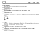
...this RGB2 Digital input for RGB2 input. ቭ To Monitor Connect the Monitor Connection Cable to the AVC center's "TO MONITOR" connector, and to the display monitors "FROM AVC" connector. ቮ IR Blaster This jack provides IR output to your external components can automatically be ...controlled by the A/V network feature. With this SUB WOOFER OUT output. ተ To AVC Connect the Monitor Connection cable from the AVC center's "TO MONITOR" to control the external components with your external devices with digital output capability (see page 22)....
...this RGB2 Digital input for RGB2 input. ቭ To Monitor Connect the Monitor Connection Cable to the AVC center's "TO MONITOR" connector, and to the display monitors "FROM AVC" connector. ቮ IR Blaster This jack provides IR output to your external components can automatically be ...controlled by the A/V network feature. With this SUB WOOFER OUT output. ተ To AVC Connect the Monitor Connection cable from the AVC center's "TO MONITOR" to control the external components with your external devices with digital output capability (see page 22)....

Owners Guide
Page 13
...you have a S-VHS VCR, use the VIDEO cable in the following examples: Front panel of AVC Front panel of your AVC box. 4. Back of Display Monitor 32HDT20 Back of Display Monitor 42HDT20 To AC outlet Core ANT A TO CONVERTER ANT B MONITOR OUT S-VIDEO INPUT 4 S-VIDEO ...VIDEO INPUT 2 Y/VIDEO INPUT 1 AUDIO AUDIO PB (MONO) L PB (MONO) L PR PR R R AUDIO R L AUDIOR L AUDIOR L AUDIO OUT IR BLASTER Back of AVC Center To AC outlet To AC outlet Core ANT A TO CONVERTER ANT B MONITOR OUT S-VIDEO INPUT 4 S-VIDEO INPUT 3 S-VIDEO VIDEO VIDEO VIDEO (MONO) L (MONO) L (...
...you have a S-VHS VCR, use the VIDEO cable in the following examples: Front panel of AVC Front panel of your AVC box. 4. Back of Display Monitor 32HDT20 Back of Display Monitor 42HDT20 To AC outlet Core ANT A TO CONVERTER ANT B MONITOR OUT S-VIDEO INPUT 4 S-VIDEO ...VIDEO INPUT 2 Y/VIDEO INPUT 1 AUDIO AUDIO PB (MONO) L PB (MONO) L PR PR R R AUDIO R L AUDIOR L AUDIOR L AUDIO OUT IR BLASTER Back of AVC Center To AC outlet To AC outlet Core ANT A TO CONVERTER ANT B MONITOR OUT S-VIDEO INPUT 4 S-VIDEO INPUT 3 S-VIDEO VIDEO VIDEO VIDEO (MONO) L (MONO) L (...
Owners Guide
Page 14
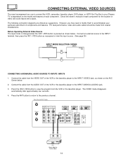
... External Video Source The input mode is changed when the VID1~VID5 button is dependent on the AVC Center below . Press the ANT button to return to the INPUT terminal, then press the VID1~VID5...coaxial shielded wire. The following connection diagrams are offered as shown on the model and features of each component for the location of AVC Center ANT A TO CONVERTER ANT B MONITOR OUT S-VIDEO INPUT 4 S-VIDEO INPUT 3 S-VIDEO VIDEO VIDEO VIDEO (MONO) (MONO)... R R AUDIO R L AUDIOR L AUDIOR L AUDIO OUT IR BLASTER AUDIO OUT VIDEO OUT VCR Hitachi Model or Similar Model 14
... External Video Source The input mode is changed when the VID1~VID5 button is dependent on the AVC Center below . Press the ANT button to return to the INPUT terminal, then press the VID1~VID5...coaxial shielded wire. The following connection diagrams are offered as shown on the model and features of each component for the location of AVC Center ANT A TO CONVERTER ANT B MONITOR OUT S-VIDEO INPUT 4 S-VIDEO INPUT 3 S-VIDEO VIDEO VIDEO VIDEO (MONO) (MONO)... R R AUDIO R L AUDIOR L AUDIOR L AUDIO OUT IR BLASTER AUDIO OUT VIDEO OUT VCR Hitachi Model or Similar Model 14
Owners Guide
Page 15
... is loose. 2. CONNECTING EXTERNAL VIDEO SOURCES CONNECTING A STEREO VCR OR STEREO LASERDISC PLAYER 1. The VIDEO label disappears automatically after approximately four seconds. 5. Rear Panel of AVC Center ANT A TO CONVERTER ANT B MONITOR OUT S-VIDEO INPUT 4 S-VIDEO INPUT 3 S-VIDEO VIDEO VIDEO VIDEO (MONO) (MONO) (MONO) L L L R AUDIO R AUDIO R AUDIO RGB 1...IR BLASTER Back of the VCR or the laserdisc player to view the program from the AUDIO OUT L of VCR R L V OUTPUT VCR Hitachi Model or Similar Model NOTES: 1. Press the ANT button to return to rear panel jacks.
... is loose. 2. CONNECTING EXTERNAL VIDEO SOURCES CONNECTING A STEREO VCR OR STEREO LASERDISC PLAYER 1. The VIDEO label disappears automatically after approximately four seconds. 5. Rear Panel of AVC Center ANT A TO CONVERTER ANT B MONITOR OUT S-VIDEO INPUT 4 S-VIDEO INPUT 3 S-VIDEO VIDEO VIDEO VIDEO (MONO) (MONO) (MONO) L L L R AUDIO R AUDIO R AUDIO RGB 1...IR BLASTER Back of the VCR or the laserdisc player to view the program from the AUDIO OUT L of VCR R L V OUTPUT VCR Hitachi Model or Similar Model NOTES: 1. Press the ANT button to return to rear panel jacks.
Owners Guide
Page 16
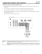
...from the AUDIO OUT L of VCR or R L V S-VIDEO Laserdisc Player OUTPUT VCR or Laserdisc Player Hitachi Model or Similar Model NOTES: 1. Connect the cable from the VCR or laserdisc player. Rear Panel of AVC Center ANT A TO CONVERTER ANT B MONITOR OUT S-VIDEO INPUT 4 S-VIDEO INPUT 3 S-VIDEO VIDEO VIDEO VIDEO...Connect the cable from the S-VIDEO OUT of the VCR or the laserdisc player to the INPUT (S-VIDEO) jack, as shown on the AVC Center below. 2. Completely insert the connection cord plugs when connecting to your VCR operating guide for more information on page 22) Refer to rear ...
...from the AUDIO OUT L of VCR or R L V S-VIDEO Laserdisc Player OUTPUT VCR or Laserdisc Player Hitachi Model or Similar Model NOTES: 1. Connect the cable from the VCR or laserdisc player. Rear Panel of AVC Center ANT A TO CONVERTER ANT B MONITOR OUT S-VIDEO INPUT 4 S-VIDEO INPUT 3 S-VIDEO VIDEO VIDEO VIDEO...Connect the cable from the S-VIDEO OUT of the VCR or the laserdisc player to the INPUT (S-VIDEO) jack, as shown on the AVC Center below. 2. Completely insert the connection cord plugs when connecting to your VCR operating guide for more information on page 22) Refer to rear ...
Owners Guide
Page 17
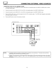
.... The picture and sound that is played back will be abnormal if the connection is loose. 2. Connect the cable from the AUDIO OUT R of the AVC Center ANT A TO CONVERTER ANT B MONITOR OUT S-VIDEO INPUT 4 S-VIDEO INPUT 3 S-VIDEO VIDEO VIDEO VIDEO (MONO) (MONO) (MONO) L L L R AUDIO R AUDIO R AUDIO RGB ...Completely insert the connection cord plugs when connecting to the previous channel. OUTPUT L R Y PB PR OR HDTV Set-Top Box DVD Player Hitachi Model or Similar Model OUTPUT Back of VIDEO AUDIO DVD Player PB/CB PR/CR Y R L Rear Panel of the Laserdisc/DVD player or...
.... The picture and sound that is played back will be abnormal if the connection is loose. 2. Connect the cable from the AUDIO OUT R of the AVC Center ANT A TO CONVERTER ANT B MONITOR OUT S-VIDEO INPUT 4 S-VIDEO INPUT 3 S-VIDEO VIDEO VIDEO VIDEO (MONO) (MONO) (MONO) L L L R AUDIO R AUDIO R AUDIO RGB ...Completely insert the connection cord plugs when connecting to the previous channel. OUTPUT L R Y PB PR OR HDTV Set-Top Box DVD Player Hitachi Model or Similar Model OUTPUT Back of VIDEO AUDIO DVD Player PB/CB PR/CR Y R L Rear Panel of the Laserdisc/DVD player or...
Owners Guide
Page 18
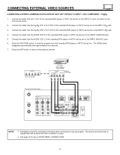
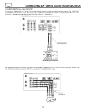
... L AUDIO OUT IR BLASTER RL INPUT To Audio Input Terminal of External Amplifier Stereo System Amplifier The MONITOR OUT terminal outputs video and audio of AVC Center ANT A TO CONVERTER ANT B MONITOR OUT S-VIDEO INPUT 4 S-VIDEO INPUT 3 S-VIDEO VIDEO VIDEO VIDEO (MONO) (MONO) (MONO) L L L R AUDIO R AUDIO R AUDIO RGB 1 ANALOG .... If a component device is input to an external audio amplifier, connect the system as shown below. The "AUDIO OUT" from the AVC center is a fixed output. The AUDIO OUT terminal outputs all audio sources (ANT A/B, INPUT 1~5 and RGB 1/2).
... L AUDIO OUT IR BLASTER RL INPUT To Audio Input Terminal of External Amplifier Stereo System Amplifier The MONITOR OUT terminal outputs video and audio of AVC Center ANT A TO CONVERTER ANT B MONITOR OUT S-VIDEO INPUT 4 S-VIDEO INPUT 3 S-VIDEO VIDEO VIDEO VIDEO (MONO) (MONO) (MONO) L L L R AUDIO R AUDIO R AUDIO RGB 1 ANALOG .... If a component device is input to an external audio amplifier, connect the system as shown below. The "AUDIO OUT" from the AVC center is a fixed output. The AUDIO OUT terminal outputs all audio sources (ANT A/B, INPUT 1~5 and RGB 1/2).
Owners Guide
Page 19
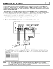
...of the infrared sensor of an A/V Network setup between your Hitachi Plasma TV Remote Control. VCR Set Top Box Cable Box Amplifier DVD POWER CH ̄ CH ̆ SETUP TV/VCR b MORE Move NOTES: 1. The AVC Center has two IR BLASTER outputs which can connect the Plasma ...Network Setup Wizard will automatically start upon the very first use your Hitachi remote control to control the Audio/Video equipment command without the equipment's remote control. Connect the IR Mouse cable to the IR BLASTER output of the AVC Center ANT A TO CONVERTER ANT B MONITOR OUT S-VIDEO INPUT 4 S-...
...of the infrared sensor of an A/V Network setup between your Hitachi Plasma TV Remote Control. VCR Set Top Box Cable Box Amplifier DVD POWER CH ̄ CH ̆ SETUP TV/VCR b MORE Move NOTES: 1. The AVC Center has two IR BLASTER outputs which can connect the Plasma ...Network Setup Wizard will automatically start upon the very first use your Hitachi remote control to control the Audio/Video equipment command without the equipment's remote control. Connect the IR Mouse cable to the IR BLASTER output of the AVC Center ANT A TO CONVERTER ANT B MONITOR OUT S-VIDEO INPUT 4 S-...
Owners Guide
Page 22
... IN S-VIDEO V L R 54321 10 9 8 7 6 15 14 13 12 11 RGB OUTPUT AUDIO OUT DIGITAL OUTPUT CAPABILITY DIGITAL OUTPUT AUDIO OUT Rear Panel of AVC Center INPUT OUTPUT Cable TV Box LR INPUT S-VIDEO V L R INPUT VCR #2 S-VIDEO V L R OUTPUT Laserdisc player, VCR, camcorder, etc. Y/VIDEO INPUT 2 ...VIDEO VIDEO VIDEO (MONO) (MONO) (MONO) L L L R AUDIO R AUDIO R AUDIO RGB 1 ANALOG INPUT RGB 2 DIGITAL INPUT TO MONITOR Please use Hitachi specified cable. OUTPUT Y PB/CB PR/CR L R DVD Player Y PB PR L R OUTPUT Stereo System Amplifier HDTV Set-Top Box NOTE: (PROVIDED) CONNECT ...
... IN S-VIDEO V L R 54321 10 9 8 7 6 15 14 13 12 11 RGB OUTPUT AUDIO OUT DIGITAL OUTPUT CAPABILITY DIGITAL OUTPUT AUDIO OUT Rear Panel of AVC Center INPUT OUTPUT Cable TV Box LR INPUT S-VIDEO V L R INPUT VCR #2 S-VIDEO V L R OUTPUT Laserdisc player, VCR, camcorder, etc. Y/VIDEO INPUT 2 ...VIDEO VIDEO VIDEO (MONO) (MONO) (MONO) L L L R AUDIO R AUDIO R AUDIO RGB 1 ANALOG INPUT RGB 2 DIGITAL INPUT TO MONITOR Please use Hitachi specified cable. OUTPUT Y PB/CB PR/CR L R DVD Player Y PB PR L R OUTPUT Stereo System Amplifier HDTV Set-Top Box NOTE: (PROVIDED) CONNECT ...
Owners Guide
Page 23
...), connect it to the operating guide of the standard video connection if your device has this feature. Refer to the left audio jack on the AVC Center. Connect only 1 component (VCR, DVD player, camcorder, etc.) to your hook-up cables. Your component outputs may be used for recording only when the input...
...), connect it to the operating guide of the standard video connection if your device has this feature. Refer to the left audio jack on the AVC Center. Connect only 1 component (VCR, DVD player, camcorder, etc.) to your hook-up cables. Your component outputs may be used for recording only when the input...
Owners Guide
Page 75
Remove the plug (AVC Center/Display Monitor) from extreme heat, humidity, and extremely dusty places. Avoid repeatedly touching the screen. Excessive heat or moisture may be used if the screen ... cause damage to shocks such as dropping it wet. Avoid placing the remote control in warm water and dry with a new battery. CARE OF YOUR HITACHI PLASMA DISPLAY AND YOUR REMOTE CONTROL DO Dust the screen with two new "AA" size batteries. Clean the screen with a soft cloth moistened in a high...
Remove the plug (AVC Center/Display Monitor) from extreme heat, humidity, and extremely dusty places. Avoid repeatedly touching the screen. Excessive heat or moisture may be used if the screen ... cause damage to shocks such as dropping it wet. Avoid placing the remote control in warm water and dry with a new battery. CARE OF YOUR HITACHI PLASMA DISPLAY AND YOUR REMOTE CONTROL DO Dust the screen with two new "AA" size batteries. Clean the screen with a soft cloth moistened in a high...
Owners Guide
Page 80
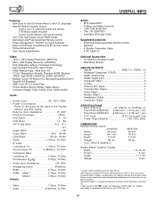
...8226; Monitor Output 1 • Headphone Output 1 • Subwoofer Output 1 SPECIFICATIONS • Multi-Scanning 24-109kHz (h), 50-85Hz (v) • Pixel Pitch(42HDT20) .....0.90(horiz.) x 0.51(vert.) mm • Pixel Pitch(32HDT20) .....0.84(horiz.) x 0.39(vert.) mm • FCC class B for custom ...access www.hitachi.com/tv for detailed specifications and imensions for Consumer Use • Power Requirements 108-132V, 60Hz DIMENSIONS Monitor without prior notice. All specifications, weights, and dimenions are trademarks of the Plasma Monitor and AVC Center •...
...8226; Monitor Output 1 • Headphone Output 1 • Subwoofer Output 1 SPECIFICATIONS • Multi-Scanning 24-109kHz (h), 50-85Hz (v) • Pixel Pitch(42HDT20) .....0.90(horiz.) x 0.51(vert.) mm • Pixel Pitch(32HDT20) .....0.84(horiz.) x 0.39(vert.) mm • FCC class B for custom ...access www.hitachi.com/tv for detailed specifications and imensions for Consumer Use • Power Requirements 108-132V, 60Hz DIMENSIONS Monitor without prior notice. All specifications, weights, and dimenions are trademarks of the Plasma Monitor and AVC Center •...


