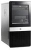
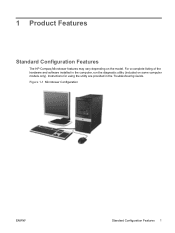
Dx2400 Microtower - HP Compaq Business Desktop
Dx2400 Microtower
Related Manual Pages


Related Videos

HP Compaq dx2400 Microtower PC (NV521UT).mp4
Duration: 3:36
Total Views: 1,064
Duration: 3:36
Total Views: 1,064
HP Compaq dx2400 Microtower PC (NV521UT)
Duration: 3:36
Total Views: 1,374
Duration: 3:36
Total Views: 1,374
HP Compaq dx2400 Microtower PC (NV520UT)
Duration: 3:24
Total Views: 1,048
Duration: 3:24
Total Views: 1,048
Similar Questions

Turn On Password
how do u bypass the password when u first turn on the hp compaq dx2400 microtower
how do u bypass the password when u first turn on the hp compaq dx2400 microtower
(Posted by Rustydollery1 2 years ago)

How To Create Partition In Hp Pro 3330 Microtower Windows 7 Pc
how to create partition in HP Pro 3330 Microtower windows 7 pc
how to create partition in HP Pro 3330 Microtower windows 7 pc
(Posted by jaswindertoura10 10 years ago)

I How Can I Reset Bios Password On Hp Compaq Dx7300 Microtower
(Posted by 74125jabu 10 years ago)

How Can I Install Windows Xp Sp 2 In Hp Pro 3330 Microtower
how can i install windows xp sp 2 in hp pro 3330 microtower and where can i find the drivers for xp
how can i install windows xp sp 2 in hp pro 3330 microtower and where can i find the drivers for xp
(Posted by kamaljugantor 11 years ago)
Related Terms
The following terms were also used when searching for Dx2400 Microtower - HP Compaq Business Desktop:- hp compaq dx2400 microtower
- dx2400 microtower
- hp dx2400 mt
- hp dx2400 microtower
- hp dx2400 micro tower
- dx2400 driver
- dx2400 micro tower
- hp dx2400 driver
- ka573ut#aba
- ka573ut aba
- kr598ut aba
- kr598ut#aba
- dx2400 memory
- dx2400 drivers
- kr601ut aba
- kr601ut#aba
- hp dx2400 kr543ut
- kr599ut aba
- dx2400 kr543ut
- dx2400 nv390ut
- dx2400 ram
- hp dx2400 drivers
- nv440ut aba
- nv440ut#aba
- dx2400 motherboard
- dx2400 network driver
- hewlett packard dx2400
- hp dx2400 e5200
- dx2400 e5200
- dx2400 manual
- dx2400 microtower specs
- dx2400 review
- dx2400 specs
- hp dx2400 computer
- hp dx2400 memory
- nv439ut aba
- nv439ut#aba
- nv521ut aba
- nv521ut#aba
- dx2400 cpu
- dx2400 power supply
- kr596ut aba
- nv364ut aba
- dx2400 bios update
- dx2400 computer
- dx2400 max ram
- dx2400 nv390ut desktop pc
- dx2400 reviews
- dx2400 video card
- hp dx2400 problem
- hp dx2400 review
- hp dx2400 specs
- ka535ut aba
- dx2400
- dx2400 64 bit drivers
- dx2400 amplifier
- dx2400 beep codes
- dx2400 bios
- dx2400 bios download
- dx2400 bios reset
- dx2400 cannot install windows 7
- dx2400 card reader
- dx2400 chassis fan
- dx2400 cpu replacement
- dx2400 cpu support
- dx2400 cpu upgrade
- dx2400 desktop
- dx2400 desktop computer
- dx2400 desktop specs
- dx2400 desktop tower
- dx2400 desktop won't turn on
- dx2400 disable video
- dx2400 downloads
- dx2400 drivers 64 bit
- dx2400 drivers download
- dx2400 drivers windows 7
- dx2400 drivers xp
- dx2400 e2180
- dx2400 ethernet driver
- dx2400 firmware
- dx2400 graphics card
- dx2400 graphics cards
- dx2400 hackintosh
- dx2400 hard drive
- dx2400 hp
- dx2400 hp drivers
- dx2400 images
- dx2400 keep rebooting 5 seconds
- dx2400 max memory
- dx2400 memory configuration
- dx2400 memory slots
- dx2400 memory specs
- dx2400 memory upgrade
- dx2400 microtower bios update
- dx2400 microtower driver
- dx2400 microtower drivers
- dx2400 microtower memory
- dx2400 microtower memory upgrade
- dx2400 microtower motherboard
- dx2400 microtower ram
- dx2400 motherboard diagram
- dx2400 motherboard specs
- dx2400 mt
- dx2400 mt drivers
- dx2400 network card
- dx2400 network drivers
- dx2400 nic driver
- dx2400 no video
- dx2400 parallel port driver
- dx2400 pci serial port driver
- dx2400 pci serial port drivers
- dx2400 pdf
- dx2400 power supply upgrade
- dx2400 problem
- dx2400 processor
- dx2400 processor support
- dx2400 processor upgrade
- dx2400 product number
- dx2400 raid
- dx2400 ram upgrade
- dx2400 recovery cds
- dx2400 recovery disc
- dx2400 recovery disk
- dx2400 release date
- dx2400 serial driver
- dx2400 serial pci adapter
- dx2400 service manual
- dx2400 service mapping
- dx2400 sm bus controller driver
- dx2400 sm windows 7 drivers
- dx2400 spec
- dx2400 specification
- dx2400 specifications
- dx2400 support
- dx2400 tower
- dx2400 video driver
- dx2400 video drivers
- dx2400 weight
- dx2400 windows 10
- dx2400 windows 7
- dx2400 windows 7 drivers
- dx2400 xp drivers
- hp compaq dx2400 microtower pc
- hp compaq dx2400 microtower pc (nv521ut)
- hp compaq dx2400 microtower pc nv521ut
- hp dx2400
- hp dx2400 64 bit drivers
- hp dx2400 beep codes
- hp dx2400 bios
- hp dx2400 bios download
- hp dx2400 bios reset
- hp dx2400 bios update
- hp dx2400 card reader
- hp dx2400 chassis fan
- hp dx2400 cpu
- hp dx2400 cpu replacement
- hp dx2400 cpu support
- hp dx2400 cpu upgrade
- hp dx2400 desktop
- hp dx2400 desktop computer
- hp dx2400 desktop specs
- hp dx2400 desktop tower
- hp dx2400 desktop won't turn on
- hp dx2400 drivers download
- hp dx2400 drivers windows 7
- hp dx2400 e2180
- hp dx2400 ethernet driver
- hp dx2400 graphics card
- hp dx2400 graphics cards
- hp dx2400 hackintosh
- hp dx2400 hard drive
- hp dx2400 images
- hp dx2400 keep rebooting 5 seconds
- hp dx2400 kr598ut intel dual core pc
- hp dx2400 manual
- hp dx2400 max memory
- hp dx2400 max ram
- hp dx2400 memory specs
- hp dx2400 memory upgrade
- hp dx2400 microtower bios update
- hp dx2400 microtower drivers
- hp dx2400 microtower memory
- hp dx2400 microtower memory upgrade
- hp dx2400 microtower specs
- hp dx2400 motherboard
- hp dx2400 motherboard specs
- hp dx2400 mt drivers
- hp dx2400 network card
- hp dx2400 network driver
- hp dx2400 nic driver
- hp dx2400 no video
- hp dx2400 nv390ut desktop pc
- hp dx2400 parallel port driver
- hp dx2400 pc
- hp dx2400 pci serial port driver
- hp dx2400 pci serial port drivers
- hp dx2400 power supply
- hp dx2400 power supply upgrade
- hp dx2400 processor
- hp dx2400 processor support
- hp dx2400 processor upgrade
- hp dx2400 product number
- hp dx2400 raid
- hp dx2400 ram
- hp dx2400 ram upgrade
- hp dx2400 recovery cds
- hp dx2400 recovery disc
- hp dx2400 recovery disk
- hp dx2400 release date
- hp dx2400 reviews
- hp dx2400 sm bus controller driver
- hp dx2400 sm windows 7 drivers
- hp dx2400 spec
- hp dx2400 specification
- hp dx2400 specifications
- hp dx2400 support
- hp dx2400 tower
- hp dx2400 video card
- hp dx2400 video driver
- hp dx2400 windows 10
- hp dx2400 windows 7
- hp dx2400 windows 7 drivers
- hp dx2400 xp drivers
- hp ka535ut aba
- hp ka573ut#aba
- hp kr598ut aba
- hp kr598ut#aba
- hp nv364ut#aba
- hp nv440ut#aba
- hp nv521ut
- hp nv521ut#aba
- ka442ut aba
- ka442ut aba number
- ka442ut aba specs
- ka442ut specifications
- ka442ut specs
- ka535ut #aba
- ka535ut aba number
- ka535ut specs
- ka535ut#aba
- ka573ut aba hp
- ka573ut aba memory
- ka573ut aba number
- ka573ut aba specs
- ka573ut review
- ka573ut specifications
- ka573ut specs
- ka573ut#aba specs
- kr596ut aba number
- kr596ut warranty
- kr596ut#aba
- kr597ut aba
- kr597ut aba number
- kr597ut#aba
- kr598ut aba hp
- kr598ut aba number
- kr598ut aba specs
- kr598ut is video on motherboard
- kr598ut price
- kr598ut smart 2 0
- kr598ut specs
- kr598ut warranty
- kr598ut#aba specs
- kr599ut aba hp
- kr599ut aba number
- kr599ut aba specs
- kr599ut memory
- kr599ut motherboard
- kr599ut specifications
- kr599ut specs
- kr599ut warranty
- kr599ut#aba
- kr600ut aba
- kr600ut aba hp
- kr600ut aba motherboard
- kr600ut aba number
- kr600ut#aba
- kr601ut aba hp
- kr601ut aba number
- kr601ut aba specs
- kr601ut pdf
- kr601ut price
- kr601ut specs
- kr601ut warranty
- kr659ut aba
- kr659ut aba number
- kr659ut aba specs
- kr659ut memory
- kr659ut specs
- kr659ut#aba
- kr741ut aba
- kr741ut aba number
- nv350ut aba
- nv350ut aba number
- nv364ut aba number
- nv364ut aba specs
- nv364ut review
- nv364ut specs
- nv364ut#aba
- nv364ut#aba specs
- nv413ut aba
- nv413ut aba number
- nv413ut pdf
- nv413ut specs
- nv413ut warranty
- nv413ut#aba
- nv439ut aba number
- nv439ut aba specs
- nv439ut review
- nv439ut specifications
- nv439ut specs
- nv440ut aba number
- nv440ut aba specifications
- nv440ut aba specs
- nv440ut price
- nv440ut review
- nv440ut warranty
- nv440ut#aba specs
- nv521ut
- nv521ut aba hp
- nv521ut aba number
- nv521ut aba specs
- nv521ut price
- nv521ut review
- nv521ut specs