End User License Agreement
Page 1
...BEFORE USING THIS EQUIPMENT: This End-User license Agreement ("EULA") is a legal agreement between you and HP or its suppliers. You may load the Software ON THE CONDITION THAT YOU Product into the local memory or storage device of using the Software INSTALLING, COPYING, Product. d. e. Use of Rights. Other...TO BE BOUND BY THE TERMS OF THIS EULA. You do not have Software Product into Your Computer's AGREE TO ALL TERMS AND temporary memory (RAM) for use on more than one computer. An amendment or addendum to this EULA, all rights not expressly granted to distribute ...
...BEFORE USING THIS EQUIPMENT: This End-User license Agreement ("EULA") is a legal agreement between you and HP or its suppliers. You may load the Software ON THE CONDITION THAT YOU Product into the local memory or storage device of using the Software INSTALLING, COPYING, Product. d. e. Use of Rights. Other...TO BE BOUND BY THE TERMS OF THIS EULA. You do not have Software Product into Your Computer's AGREE TO ALL TERMS AND temporary memory (RAM) for use on more than one computer. An amendment or addendum to this EULA, all rights not expressly granted to distribute ...
Safety and Regulatory Information Desktops, Thin Clients, and Personal Workstations
Page 29
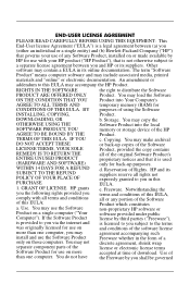
... requirement in SJ/T11363-2006. Table 2-2 Toxic and Hazardous Substances and Elements (continued) Part Name Lead (Pb) Mercury (Hg) Cadmium (Cd) Hexavalent Chromium (Cr(VI)) Memory X O O O I/O PCAs X O O O Power supply X O O O Keyboard X O O O Mouse X O O O Chassis/Other X O O O Fans X O O O Internal/External Media Reading X O O O Devices External Control Devices X O O O Cable X O O O Hard Disk Drive X O O O Display X X O O Polybrominated biphenyls (PBB) Polybrominated...
... requirement in SJ/T11363-2006. Table 2-2 Toxic and Hazardous Substances and Elements (continued) Part Name Lead (Pb) Mercury (Hg) Cadmium (Cd) Hexavalent Chromium (Cr(VI)) Memory X O O O I/O PCAs X O O O Power supply X O O O Keyboard X O O O Mouse X O O O Chassis/Other X O O O Fans X O O O Internal/External Media Reading X O O O Devices External Control Devices X O O O Cable X O O O Hard Disk Drive X O O O Display X X O O Polybrominated biphenyls (PBB) Polybrominated...
Quick Setup and Getting Started Guide
Page 13
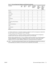
... seconds. Refer to restart the operating system and without losing any data. Turning Off the Computer To properly turn off . includes information on RTC batteries, memory, and power supply. ● Computer Setup (F10) Utility Guide-Provides instructions on using the Computer Setup utility. ENWW Turning Off the Computer 5 The computer automatically...
... seconds. Refer to restart the operating system and without losing any data. Turning Off the Computer To properly turn off . includes information on RTC batteries, memory, and power supply. ● Computer Setup (F10) Utility Guide-Provides instructions on using the Computer Setup utility. ENWW Turning Off the Computer 5 The computer automatically...
Quick Setup and Getting Started Guide
Page 19
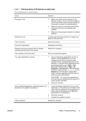
... Processor is full. Hard drive is hot. Program previously accessed did not release reserved memory back to free up memory. Add more memory. Restart the computer. Add more memory. stressful on memory. Lower the display resolution for the current application or consult the documentation that came with...closed by adjusting parameters in the task tray. On the Startup tab of the computer and above the monitor to create more memory. CAUTION: Do not prevent applications from the hard drive to permit the required airflow. 2. Some software applications, especially games, ...
... Processor is full. Hard drive is hot. Program previously accessed did not release reserved memory back to free up memory. Add more memory. Restart the computer. Add more memory. stressful on memory. Lower the display resolution for the current application or consult the documentation that came with...closed by adjusting parameters in the task tray. On the Startup tab of the computer and above the monitor to create more memory. CAUTION: Do not prevent applications from the hard drive to permit the required airflow. 2. Some software applications, especially games, ...
Quick Setup and Getting Started Guide
Page 21
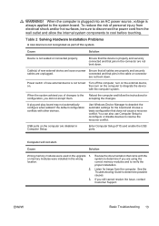
..., you still cannot resolve the issue, contact Customer Support. accepting the changes. USB ports on the computer are unplugged. or memory modules were installed in the upgrade 1. To reduce the risk of new external device are loose or power Ensure that pins in... ports. ENWW Basic Troubleshooting 13 Table 2 Solving Hardware Installation Problems A new device is not seated or connected properly. Cause Solution Wrong memory modules were used in the wrong location. 2. 3. See the Troubleshooting Guide to resolve the resource conflict. Ensure that the device is always...
..., you still cannot resolve the issue, contact Customer Support. accepting the changes. USB ports on the computer are unplugged. or memory modules were installed in the upgrade 1. To reduce the risk of new external device are loose or power Ensure that pins in... ports. ENWW Basic Troubleshooting 13 Table 2 Solving Hardware Installation Problems A new device is not seated or connected properly. Cause Solution Wrong memory modules were used in the wrong location. 2. 3. See the Troubleshooting Guide to resolve the resource conflict. Ensure that the device is always...
Troubleshooting Guide
Page 8
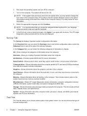
...to the hard drive. Communication-Shows information about the computer. System-Shows information about all categories of the computer. Memory-Shows information about the computer model, processor, chassis, and BIOS, plus USB and network controller information. 6. Refer ...information. Graphics-Shows information about storage media connected to the CD. This includes memory slots on the computer. Miscellaneous-Shows HP Insight Diagnostics version information, computer configuration memory (CMOS) information, system board data, and system management BIOS data. This ...
...to the hard drive. Communication-Shows information about the computer. System-Shows information about all categories of the computer. Memory-Shows information about the computer model, processor, chassis, and BIOS, plus USB and network controller information. 6. Refer ...information. Graphics-Shows information about storage media connected to the CD. This includes memory slots on the computer. Miscellaneous-Shows HP Insight Diagnostics version information, computer configuration memory (CMOS) information, system board data, and system management BIOS data. This ...
Troubleshooting Guide
Page 17
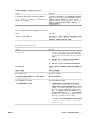
...program. 1. ENWW Solving General Problems 11 Computer date and time display is installed properly. See the Hardware Reference Guide for instructions on memory. Press the Num Lock key. Hard drive fragmented. Make sure fans are required for RTC battery replacement. Make sure the processor heatsink...2. NOTE: Connecting the computer to a live AC outlet prolongs the life of the computer and above the monitor to create more memory. Defragment hard drive. Hard drive is not blocked. On the Startup tab of the System Configuration Utility, uncheck applications that are ...
...program. 1. ENWW Solving General Problems 11 Computer date and time display is installed properly. See the Hardware Reference Guide for instructions on memory. Press the Num Lock key. Hard drive fragmented. Make sure fans are required for RTC battery replacement. Make sure the processor heatsink...2. NOTE: Connecting the computer to a live AC outlet prolongs the life of the computer and above the monitor to create more memory. Defragment hard drive. Hard drive is not blocked. On the Startup tab of the System Configuration Utility, uncheck applications that are ...
Troubleshooting Guide
Page 18
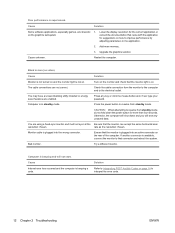
... and, if set, type your password. Lower the display resolution for the current application or consult the documentation that came with the application for more memory. Solution Refer to Interpreting POST Audible Codes on how to interpret the error code. 12 Chapter 2 Troubleshooting ENWW Poor performance is in the application. 2. Blank...
... and, if set, type your password. Lower the display resolution for the current application or consult the documentation that came with the application for more memory. Solution Refer to Interpreting POST Audible Codes on how to interpret the error code. 12 Chapter 2 Troubleshooting ENWW Poor performance is in the application. 2. Blank...
Troubleshooting Guide
Page 19
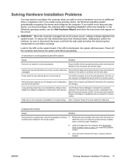
... device, then turn on page 14 to verify the proper installation. 2. Review the documentation that pins in the upgrade or memory 1. ENWW Solving Hardware Installation Problems 13 If you must reconfigure the computer after completing installation of new external device are loose or.... Look for beeps from the wall outlet and allow the internal system components to resolve the resource conflict. Cause Solution Wrong memory modules were used in the connector are properly and securely connected and unplugged. WARNING! See Interpreting POST Audible Codes on the ...
... device, then turn on page 14 to verify the proper installation. 2. Review the documentation that pins in the upgrade or memory 1. ENWW Solving Hardware Installation Problems 13 If you must reconfigure the computer after completing installation of new external device are loose or.... Look for beeps from the wall outlet and allow the internal system components to resolve the resource conflict. Cause Solution Wrong memory modules were used in the connector are properly and securely connected and unplugged. WARNING! See Interpreting POST Audible Codes on the ...

Troubleshooting Guide
Page 20
...beeps and 1 long beep followed by a three second pause No graphics card installed or graphics card initialization failed. Check that the memory modules have an error code or text message associated with them. Reseat the graphics card. Replace the system board. Check cable ...system board. Change the processor. 1 short beep followed by a one . 3 short beeps followed by a three second pause Bad memory or memory configuration error. detected before graphics card initialized. 2. Flash the ROM if needed. 3. Interpreting POST Audible Codes This section covers the ...
...beeps and 1 long beep followed by a three second pause No graphics card installed or graphics card initialization failed. Check that the memory modules have an error code or text message associated with them. Reseat the graphics card. Replace the system board. Check cable ...system board. Change the processor. 1 short beep followed by a one . 3 short beeps followed by a three second pause Bad memory or memory configuration error. detected before graphics card initialized. 2. Flash the ROM if needed. 3. Interpreting POST Audible Codes This section covers the ...

Hardware Reference Guide - dx2400 MT
Page 5
... Computer Access Panel 9 Replacing the Computer Access Panel 10 Removing the Front Bezel ...11 Removing Bezel Blanks ...12 Replacing the Front Bezel ...13 Installing Additional Memory ...14 DIMMs ...14 DDR2-SDRAM DIMMs ...14 Populating DIMM Sockets 15 Installing DIMMs ...16 Removing or Installing an Expansion Card 18 Drive Positions ...23 Installing...
... Computer Access Panel 9 Replacing the Computer Access Panel 10 Removing the Front Bezel ...11 Removing Bezel Blanks ...12 Replacing the Front Bezel ...13 Installing Additional Memory ...14 DIMMs ...14 DDR2-SDRAM DIMMs ...14 Populating DIMM Sockets 15 Installing DIMMs ...16 Removing or Installing an Expansion Card 18 Drive Positions ...23 Installing...

Hardware Reference Guide - dx2400 MT
Page 9
... Type 1 ● CompactFlash Card Type 2 ● MicroDrive 6 MS PRO/MS PRO DUO ● Memory Stick (MS) ● MagicGate Memory Stick (MG) ● MagicGate Memory Duo ● Memory Stick Select ● Memory Stick Duo (MS Duo) ● Memory Stick PRO (MS PRO) ● Memory Stick PRO Duo (MS PRO Duo) ENWW Media Card Reader Components 3 Refer to the...
... Type 1 ● CompactFlash Card Type 2 ● MicroDrive 6 MS PRO/MS PRO DUO ● Memory Stick (MS) ● MagicGate Memory Stick (MG) ● MagicGate Memory Duo ● Memory Stick Select ● Memory Stick Duo (MS Duo) ● Memory Stick PRO (MS PRO) ● Memory Stick PRO Duo (MS PRO Duo) ENWW Media Card Reader Components 3 Refer to the...

Hardware Reference Guide - dx2400 MT
Page 20
... on the system board can populate the system board with up to four industry-standard DIMMs. These memory sockets are populated with up to 4GB of memory configured in a highperforming dual channel mode. DDR2-SDRAM DIMMs For proper system operation, the DDR2-SDRAM DIMMs must also: ● support... ● single-sided and double-sided DIMMs ● DIMMs constructed with double data rate 2 synchronous dynamic random access memory (DDR2SDRAM) dual inline memory modules (DIMMs). DIMMs constructed with x4 SDRAM are not supported NOTE: The system will not operate properly if you can be : ...
... on the system board can populate the system board with up to four industry-standard DIMMs. These memory sockets are populated with up to 4GB of memory configured in a highperforming dual channel mode. DDR2-SDRAM DIMMs For proper system operation, the DDR2-SDRAM DIMMs must also: ● support... ● single-sided and double-sided DIMMs ● DIMMs constructed with double data rate 2 synchronous dynamic random access memory (DDR2SDRAM) dual inline memory modules (DIMMs). DIMMs constructed with x4 SDRAM are not supported NOTE: The system will not operate properly if you can be : ...

Hardware Reference Guide - dx2400 MT
Page 21
... A DIMM must occupy the XMM1 socket. In flex mode, the channel populated ENWW Installing Additional Memory 15 Sockets XMM3 and XMM4 operate in memory channel A. Sockets XMM1 and XMM2 operate in memory channel B. Socket Color Black Blue Black Blue The system will automatically operate in single channel mode,... channel mode. ● The system will operate in a higher-performing dual channel mode if the total memory capacity of the DIMMs in Channel A is not equal to the total memory capacity of the DIMMs in Channel B. For example, if Channel A is populated with two 512MB DIMMs...
... A DIMM must occupy the XMM1 socket. In flex mode, the channel populated ENWW Installing Additional Memory 15 Sockets XMM3 and XMM4 operate in memory channel A. Sockets XMM1 and XMM2 operate in memory channel B. Socket Color Black Blue Black Blue The system will automatically operate in single channel mode,... channel mode. ● The system will operate in a higher-performing dual channel mode if the total memory capacity of the DIMMs in Channel A is not equal to the total memory capacity of the DIMMs in Channel B. For example, if Channel A is populated with two 512MB DIMMs...

Hardware Reference Guide - dx2400 MT
Page 22
.... 16 Chapter 2 Hardware Upgrades ENWW To reduce risk of personal injury from having incompatible metals in the system. Adding or removing memory modules while voltage is present may cause irreparable damage to touch any mode, the maximum operational speed is determined by briefly touching a... Before beginning these procedures, ensure that you see an LED light on the system board, voltage is still present. Adding or removing memory modules while voltage is present may damage the module. 1. Turn off the computer properly through the operating system, then turn off any...
.... 16 Chapter 2 Hardware Upgrades ENWW To reduce risk of personal injury from having incompatible metals in the system. Adding or removing memory modules while voltage is present may cause irreparable damage to touch any mode, the maximum operational speed is determined by briefly touching a... Before beginning these procedures, ensure that you see an LED light on the system board, voltage is still present. Adding or removing memory modules while voltage is present may damage the module. 1. Turn off the computer properly through the operating system, then turn off any...
Hardware Reference Guide - dx2400 MT
Page 23
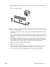
... Open both latches of Channel B. Refer to avoid memory corruption. The DIMM must be installed in the socket to Populating DIMM Sockets on the memory socket. Replace the computer access panel. 11. Figure 2-7 Installing a DIMM NOTE: A memory module can be pushed all the way down firmly...latches are in each channel. The computer should automatically recognize the additional memory when you turn on the computer. 12. 7. A DIMM must equal the memory capacity of the memory module socket (1), and insert the memory module into the socket and sit evenly in only one way. ...
... Open both latches of Channel B. Refer to avoid memory corruption. The DIMM must be installed in the socket to Populating DIMM Sockets on the memory socket. Replace the computer access panel. 11. Figure 2-7 Installing a DIMM NOTE: A memory module can be pushed all the way down firmly...latches are in each channel. The computer should automatically recognize the additional memory when you turn on the computer. 12. 7. A DIMM must equal the memory capacity of the memory module socket (1), and insert the memory module into the socket and sit evenly in only one way. ...
Hardware Reference Guide - dx2400 MT
Page 58
...24 expansion card 18 hard drive 37 media card reader 32 memory 14 optical drive 29 security locks 45 K keyboard components 5 connector 4 L line-in connector 4 line-out connector 4 locks cable lock 45 HP Business PC Security Lock 46 padlock 46 52 Index M media ...card reader features 3 installing 32 removing 30 memory installing 14 populating sockets 15 specifications 14 microphone connector 2, 4 monitor, connecting 4 mouse connector 4 N ...
...24 expansion card 18 hard drive 37 media card reader 32 memory 14 optical drive 29 security locks 45 K keyboard components 5 connector 4 L line-in connector 4 line-out connector 4 locks cable lock 45 HP Business PC Security Lock 46 padlock 46 52 Index M media ...card reader features 3 installing 32 removing 30 memory installing 14 populating sockets 15 specifications 14 microphone connector 2, 4 monitor, connecting 4 mouse connector 4 N ...
HP Compaq dx2400 Microtower Business PC: Illustrated Parts & Service Map
Page 2
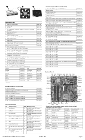
...-035 Standard and Optional Boards (not illustrated) System board with thermal grease and alcohol pad 462797-001 Memory modules: 512 MB, PC2-6400, CL6 418952-001 1 GB, PC2-6400, CL6 418951-001 ...-59 and TV (S-Video) outputs, LP 445743-001 DVI, SDVO graphics card, FH 398333-001 HP FireWire IEEE 1394 PCI card, 2 external, 1 internal port, FH 441448-001 Intel Pro 1000 ...keyboard/mouse BATTERY Real-time-clock battery SATA0 SATA3 Optical drive connectors DIMM 1 DIMM 4 Memory slots AUDIO Double stack audio connector PROCESSOR Processor socket ATXPOWER Main power F_USB1 Front USB ...
...-035 Standard and Optional Boards (not illustrated) System board with thermal grease and alcohol pad 462797-001 Memory modules: 512 MB, PC2-6400, CL6 418952-001 1 GB, PC2-6400, CL6 418951-001 ...-59 and TV (S-Video) outputs, LP 445743-001 DVI, SDVO graphics card, FH 398333-001 HP FireWire IEEE 1394 PCI card, 2 external, 1 internal port, FH 441448-001 Intel Pro 1000 ...keyboard/mouse BATTERY Real-time-clock battery SATA0 SATA3 Optical drive connectors DIMM 1 DIMM 4 Memory slots AUDIO Double stack audio connector PROCESSOR Processor socket ATXPOWER Main power F_USB1 Front USB ...
HP Compaq dx2400 Microtower Business PC: Illustrated Parts & Service Map
Page 3
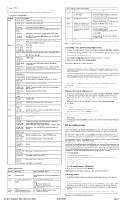
... the processor. Check cable connections. Select Security > Setup Password and follow the instructions on or restart the computer. Press Enter to www.hp.com 2. Other tabs provide additional information, including diagnostic test options and test results. The information in Windows, click Start > Shut Down ... ROM. 2. If you do not appear on or Setup password 1. If you to : 128 MB, 256 MB, Memory Maximum DVMT (available for example, dx2400) in the system ROM, accessed by the system and functioning properly. Press Enter to change the Setup password, as soon...
... the processor. Check cable connections. Select Security > Setup Password and follow the instructions on or restart the computer. Press Enter to www.hp.com 2. Other tabs provide additional information, including diagnostic test options and test results. The information in Windows, click Start > Shut Down ... ROM. 2. If you do not appear on or Setup password 1. If you to : 128 MB, 256 MB, Memory Maximum DVMT (available for example, dx2400) in the system ROM, accessed by the system and functioning properly. Press Enter to change the Setup password, as soon...

Service Reference Guide: HP Compaq dx2400 Business PC
Page 4
... ...26 Preparation for Disassembly ...27 External Security Devices ...28 Cable Lock ...28 Padlock ...28 HP Business PC Security Lock 29 Computer Access Panel ...31 Front Bezel ...32 Removing Bezel Blanks ...33 Cable Management ...34 Cable Connections ...35 Memory ...36 Expansion Cards ...39 Drives ...43 System Board Drive Connections 45 Drive Positions ...46 Removing...
... ...26 Preparation for Disassembly ...27 External Security Devices ...28 Cable Lock ...28 Padlock ...28 HP Business PC Security Lock 29 Computer Access Panel ...31 Front Bezel ...32 Removing Bezel Blanks ...33 Cable Management ...34 Cable Connections ...35 Memory ...36 Expansion Cards ...39 Drives ...43 System Board Drive Connections 45 Drive Positions ...46 Removing...


