Manual
Page 4
...GA-M51GM-S2G Motherboard Layout 7 Block Diagram ...8 Chapter 1 Hardware Installation 9 1-1 Considerations Prior to Installation 9 1-2 Feature Summary 10 1-3 Installation of the CPU and CPU Cooler 12 1-3-1 Installation of the CPU 12 1-3-2 Installation of the CPU cooler 13 1-4 Installation of Memory 14 1-5 Installation of Expansion Cards 16 1-6 I/O Back Panel Introduction 17 1-7 Connectors Introduction 18 Chapter 2 BIOS... Setup 29 The Main Menu (For example: BIOS Ver. : F2 30 2-1 Standard CMOS Features 32 2-2 Advanced BIOS Features 35 2-3 ...
...GA-M51GM-S2G Motherboard Layout 7 Block Diagram ...8 Chapter 1 Hardware Installation 9 1-1 Considerations Prior to Installation 9 1-2 Feature Summary 10 1-3 Installation of the CPU and CPU Cooler 12 1-3-1 Installation of the CPU 12 1-3-2 Installation of the CPU cooler 13 1-4 Installation of Memory 14 1-5 Installation of Expansion Cards 16 1-6 I/O Back Panel Introduction 17 1-7 Connectors Introduction 18 Chapter 2 BIOS... Setup 29 The Main Menu (For example: BIOS Ver. : F2 30 2-1 Standard CMOS Features 32 2-2 Advanced BIOS Features 35 2-3 ...

Manual
Page 5
Chapter 3 Drivers Installation 49 3-1 Install Chipset Drivers 49 3-2 SoftwareApplications 50 3-3 Driver CD Information 50 3-4 Hardware Information 51 3-5 Contact Us ...51 Chapter 4 Appendix 53 4-1 Unique Software Utilities 53 4-1-1 EasyTune 5 Introduction 53 4-1-2 Xpress Recovery2 Introduction 54 4-1-3 Flash BIOS Method Introduction 56 4-1-4 Configuring SATA Hard Drive(s 65 4-1-5 2- / 4- / 6- / 8- Channel Audio Function Introduction 79 4-2 Troubleshooting 83 - 5 -
Chapter 3 Drivers Installation 49 3-1 Install Chipset Drivers 49 3-2 SoftwareApplications 50 3-3 Driver CD Information 50 3-4 Hardware Information 51 3-5 Contact Us ...51 Chapter 4 Appendix 53 4-1 Unique Software Utilities 53 4-1-1 EasyTune 5 Introduction 53 4-1-2 Xpress Recovery2 Introduction 54 4-1-3 Flash BIOS Method Introduction 56 4-1-4 Configuring SATA Hard Drive(s 65 4-1-5 2- / 4- / 6- / 8- Channel Audio Function Introduction 79 4-2 Troubleshooting 83 - 5 -

Manual
Page 8
Block Diagram PCI-ECLK (100MHz) VGA PCI Express x 16 PCI-ECLK x 1 (100MHz) 1 PCI Express x 1 LAN RJ45 Marvell 88E1116 PCI Bus TSB43AB23 AMD Socket AM2 CPU CPUCLK+/-(200MHz) DDRII 800/667/533/400MHz DIMM Dual Channel Memory Hyper Transport Bus nVIDIA® GeForce 6100 nVIDIA® nForce 430 ATA33/66/100/133 IDE Channels 4 SATA 3Gb/s BIOS LPC BUS IT8716 Floppy LPT Port COM Ports CODEC PS/2 KB/Mouse 2PCI PCICLK (33MHz) 8 USB Ports 3 IEEE1394a Surround Speaker Out Center/Subwoofer Speaker Out Side Speaker Out MIC Line-Out Line-In SPDIF In SPDIF Out - 8 -
Block Diagram PCI-ECLK (100MHz) VGA PCI Express x 16 PCI-ECLK x 1 (100MHz) 1 PCI Express x 1 LAN RJ45 Marvell 88E1116 PCI Bus TSB43AB23 AMD Socket AM2 CPU CPUCLK+/-(200MHz) DDRII 800/667/533/400MHz DIMM Dual Channel Memory Hyper Transport Bus nVIDIA® GeForce 6100 nVIDIA® nForce 430 ATA33/66/100/133 IDE Channels 4 SATA 3Gb/s BIOS LPC BUS IT8716 Floppy LPT Port COM Ports CODEC PS/2 KB/Mouse 2PCI PCICLK (33MHz) 8 USB Ports 3 IEEE1394a Surround Speaker Out Center/Subwoofer Speaker Out Side Speaker Out MIC Line-Out Line-In SPDIF In SPDIF Out - 8 -
Manual
Page 11
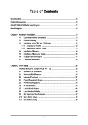
...CPU / System fan failure warning Š Supports CPU / System Smart Fan function(Note 2) BIOS Š 1 4Mbit flash ROM Š Use of licensed AWARD BIOS Additional Features Š Supports @BIOS Š Supports Download Center Š Supports Q-Flash Š Supports EasyTune (only supports Hardware... Monitor function)(Note 3) Š Supports Xpress Install Š Supports Xpress Recovery2 Š Supports Xpress BIOS Rescue Bundle Software Š Norton Internet Security (OEM version) Form Factor Š Micro ATX form factor; 24.4cm x 24.4cm...
...CPU / System fan failure warning Š Supports CPU / System Smart Fan function(Note 2) BIOS Š 1 4Mbit flash ROM Š Use of licensed AWARD BIOS Additional Features Š Supports @BIOS Š Supports Download Center Š Supports Q-Flash Š Supports EasyTune (only supports Hardware... Monitor function)(Note 3) Š Supports Xpress Install Š Supports Xpress Recovery2 Š Supports Xpress BIOS Rescue Bundle Software Š Norton Internet Security (OEM version) Form Factor Š Micro ATX form factor; 24.4cm x 24.4cm...
Manual
Page 14
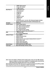
... be installed in only one direction. A memory module can only fit in one direction. The motherboard supports DDR II memory modules, whereby BIOS will automatically detect memory capacity and specifications. GA-M51GM-S2G Motherboard - 14 - It is recommended that they can differ with the following conditions: 1. Insert the DIMM memory module vertically into the...
... be installed in only one direction. A memory module can only fit in one direction. The motherboard supports DDR II memory modules, whereby BIOS will automatically detect memory capacity and specifications. GA-M51GM-S2G Motherboard - 14 - It is recommended that they can differ with the following conditions: 1. Insert the DIMM memory module vertically into the...
Manual
Page 16
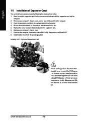
... of expansion card from BIOS. 8. Read the related expansion card's instruction document before install the expansion card into expansion slot in the slot. 5. Power on the slot. Press the expansion card firmly into the computer. 2. Make sure your computer's chassis cover, screws and slot bracket from the operating system. GA-M51GM-S2G Motherboard - 16 -
... of expansion card from BIOS. 8. Read the related expansion card's instruction document before install the expansion card into expansion slot in the slot. 5. Power on the slot. Press the expansion card firmly into the computer. 2. Make sure your computer's chassis cover, screws and slot bracket from the operating system. GA-M51GM-S2G Motherboard - 16 -

Manual
Page 21
... devices, please set the jumper on one IDE cable, and the single IDE cable can provide up to 300MB/s transfer rate. Please refer to the BIOS setting for information on settings, please refer to work properly. Hardware Installation English 6) IDE1 / IDE2 (IDE Connector) An IDE device connects to two IDE devices...
... devices, please set the jumper on one IDE cable, and the single IDE cable can provide up to 300MB/s transfer rate. Please refer to the BIOS setting for information on settings, please refer to work properly. Hardware Installation English 6) IDE1 / IDE2 (IDE Connector) An IDE device connects to two IDE devices...
Manual
Page 24
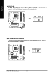
English 12) POWER_LED The PWR_LED connector is connected with the system power indicator to detect if the chassis cover is on/off. It will blink when the system enters suspend mode. You can check the "Case Opened" status in BIOS Setup. Pin No. Definition 1 1 MPD+ 2 MPD- 3 MPD- 13) CI (Chassis Intrusion, Case Open) This 2-pin connector allows your system to indicate whether the system is removed. Definition 1 1 Signal 2 GND GA-M51GM-S2G Motherboard - 24 - Pin No.
English 12) POWER_LED The PWR_LED connector is connected with the system power indicator to detect if the chassis cover is on/off. It will blink when the system enters suspend mode. You can check the "Case Opened" status in BIOS Setup. Pin No. Definition 1 1 MPD+ 2 MPD- 3 MPD- 13) CI (Chassis Intrusion, Case Open) This 2-pin connector allows your system to indicate whether the system is removed. Definition 1 1 Signal 2 GND GA-M51GM-S2G Motherboard - 24 - Pin No.
Manual
Page 29
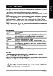
... with caution and avoid inadequate operation that does not require users to boot to select item Select Item Main Menu - English Chapter 2 BIOS Setup BIOS (Basic Input and Output System) includes a CMOS SETUP utility which allows user to configure required settings or to use and the possible ... the power is turned off, the battery on , pressing the button during the BIOS POST (Power-On Self Test) will take you wish to upgrade to the CMOS SETUP screen. If you to a new BIOS, either GIGABYTE's Q-Flash or @BIOS utility can enter the BIOS setup screen by pressing "Ctrl + F1".
... with caution and avoid inadequate operation that does not require users to boot to select item Select Item Main Menu - English Chapter 2 BIOS Setup BIOS (Basic Input and Output System) includes a CMOS SETUP utility which allows user to configure required settings or to use and the possible ... the power is turned off, the battery on , pressing the button during the BIOS POST (Power-On Self Test) will take you wish to upgrade to the CMOS SETUP screen. If you to a new BIOS, either GIGABYTE's Q-Flash or @BIOS utility can enter the BIOS setup screen by pressing "Ctrl + F1".
Manual
Page 30
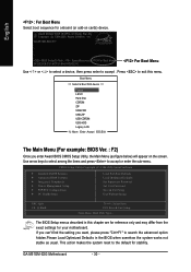
...Legacy LAN KL:Move Enter :Accept ESC:Exit The Main Menu (For example: BIOS Ver. : F2) Once you want, please press "Ctrl+F1" to the default for stability. GA-M51GM-S2G E17 . . . . :BIOS Setup/Q-Flash, : XpressRecovery2, For Boot Menu 04/03/2006-C51-MCP51-6A61HG0GC... from the exact settings for your motherboard. GA-M51GM-S2G Motherboard - 30 - English : For Boot Menu Select boot sequence for onboard (or add-on the screen. CMOS Setup Utility-Copyright (C) 1984-2006 Award Software ` Standard CMOS Features ` Advanced BIOS Features ` Integrated Peripherals ` Power Management Setup...
...Legacy LAN KL:Move Enter :Accept ESC:Exit The Main Menu (For example: BIOS Ver. : F2) Once you want, please press "Ctrl+F1" to the default for stability. GA-M51GM-S2G E17 . . . . :BIOS Setup/Q-Flash, : XpressRecovery2, For Boot Menu 04/03/2006-C51-MCP51-6A61HG0GC... from the exact settings for your motherboard. GA-M51GM-S2G Motherboard - 30 - English : For Boot Menu Select boot sequence for onboard (or add-on the screen. CMOS Setup Utility-Copyright (C) 1984-2006 Award Software ` Standard CMOS Features ` Advanced BIOS Features ` Integrated Peripherals ` Power Management Setup...

Manual
Page 31
BIOS Setup English „ Standard CMOS Features This setup page includes all the items in best performance configuration. „ Set Supervisor Password Change, set , or disable ... in safe configuration. „ Load Optimized Defaults Optimized Defaults indicates the value of the system parameters which the system would be in standard compatible BIOS. „ Advanced BIOS Features This setup page includes all the items of Award special enhanced features. „ Integrated Peripherals This setup page includes all onboard peripherals. „...
BIOS Setup English „ Standard CMOS Features This setup page includes all the items in best performance configuration. „ Set Supervisor Password Change, set , or disable ... in safe configuration. „ Load Optimized Defaults Optimized Defaults indicates the value of the system parameters which the system would be in standard compatible BIOS. „ Advanced BIOS Features This setup page includes all the items of Award special enhanced features. „ Integrated Peripherals This setup page includes all onboard peripherals. „...
Manual
Page 32
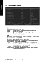
Through Dec. The time is 13:00:00. IDE Device Setup. Manual User can use one of three methods: Auto Allows BIOS to Sat, determined by the BIOS and is , , , . The four options are used and the system will skip the automatic detection step and allow for faster system... year, from Sun to automatically detect IDE devices during POST(default) None Select this if no IDE devices are : CHS/LBA/Large/Auto(default:Auto) GA-M51GM-S2G Motherboard - 32 - IDE Channel 0 Master, Slave, IDE Channel 1 Master, Slave IDE HDD Auto-Detection Press "Enter" to Sat. to select this ...
Through Dec. The time is 13:00:00. IDE Device Setup. Manual User can use one of three methods: Auto Allows BIOS to Sat, determined by the BIOS and is , , , . The four options are used and the system will skip the automatic detection step and allow for faster system... year, from Sun to automatically detect IDE devices during POST(default) None Select this if no IDE devices are : CHS/LBA/Large/Auto(default:Auto) GA-M51GM-S2G Motherboard - 32 - IDE Channel 0 Master, Slave, IDE Channel 1 Master, Slave IDE HDD Auto-Detection Press "Enter" to Sat. to select this ...

Manual
Page 33
... double-sided drive; 1.44M byte capacity. (Default value) 2.88M, 3.5" 3.5 inch double-sided drive; 2.88M byte capacity. All Errors Whenever the BIOS detects a non-fatal error the system will not stop for a disk error; it will stop for all other errors. None No floppy drive installed 360K...and you will not stop for Japan Area) Disabled Normal Floppy Drive. (Default value) Drive A Drive A is 3 mode Floppy Drive. BIOS Setup Floppy 3 Mode Support (for a keyboard or disk error; Cylinder Number of cylinders Head Number of heads Precomp Write precomp Landing Zone...
... double-sided drive; 1.44M byte capacity. (Default value) 2.88M, 3.5" 3.5 inch double-sided drive; 2.88M byte capacity. All Errors Whenever the BIOS detects a non-fatal error the system will not stop for a disk error; it will stop for all other errors. None No floppy drive installed 360K...and you will not stop for Japan Area) Disabled Normal Floppy Drive. (Default value) Drive A Drive A is 3 mode Floppy Drive. BIOS Setup Floppy 3 Mode Support (for a keyboard or disk error; Cylinder Number of cylinders Head Number of heads Precomp Write precomp Landing Zone...

Manual
Page 34
Base Memory The POST of the BIOS will determine the amount of base (or conventional) memory installed in the CPU's memory address map. This is typically 512K for systems with 512K memory .... English Memory The category is display-only which is present during the POST. Extended Memory The BIOS determines how much extended memory is determined by POST (Power On Self Test) of memory located above 1 MB in the system. GA-M51GM-S2G Motherboard - 34 - The value of the base memory is the amount of the...
Base Memory The POST of the BIOS will determine the amount of base (or conventional) memory installed in the CPU's memory address map. This is typically 512K for systems with 512K memory .... English Memory The category is display-only which is present during the POST. Extended Memory The BIOS determines how much extended memory is determined by POST (Power On Self Test) of memory located above 1 MB in the system. GA-M51GM-S2G Motherboard - 34 - The value of the base memory is the amount of the...
Manual
Page 35
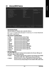
... Defaults F1: General Help Hard Disk Boot Priority Select boot sequence for floppy disk drive to determine it is 360K. (Default value) - 35 - BIOS Setup Disabled Disable this menu. Press to move it down the list. CDROM Select your boot device priority by CDROM. Use < > or < >... to select a device, then press to move it up, or to exit this function. Enabled BIOS searches for onboard(or add-on cards) SCSI, RAID, etc. First / Second / Third Boot Device Floppy Select your boot device priority by Floppy. ...
... Defaults F1: General Help Hard Disk Boot Priority Select boot sequence for floppy disk drive to determine it is 360K. (Default value) - 35 - BIOS Setup Disabled Disable this menu. Press to move it down the list. CDROM Select your boot device priority by CDROM. Use < > or < >... to select a device, then press to move it up, or to exit this function. Enabled BIOS searches for onboard(or add-on cards) SCSI, RAID, etc. First / Second / Third Boot Device Floppy Select your boot device priority by Floppy. ...
Manual
Page 37
...` KLJI: Move Enter: Select F5: Previous Values +/-/PU/PD: Value F10: Save F6: Fail-Safe Defaults ESC: Exit F1: General Help F7: Optimized Defaults - 37 - BIOS Setup
...` KLJI: Move Enter: Select F5: Previous Values +/-/PU/PD: Value F10: Save F6: Fail-Safe Defaults ESC: Exit F1: General Help F7: Optimized Defaults - 37 - BIOS Setup
Manual
Page 39
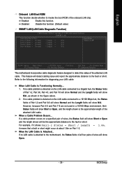
... the length shown will be the approximate distance to the fault or short. However, because Pair 4-5 and Pair 7-8 are not used in the figure above. 2. BIOS Setup Disabled Disable this function.
... the length shown will be the approximate distance to the fault or short. However, because Pair 4-5 and Pair 7-8 are not used in the figure above. 2. BIOS Setup Disabled Disable this function.
Manual
Page 40
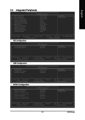
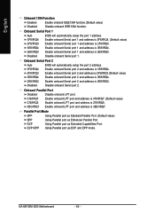
Onboard Serial Port 2 Auto 3F8/IRQ4 BIOS will automatically setup the port 1 address. 3F8/IRQ4 2F8/IRQ3 3E8/IRQ4 Enable onboard Serial port 1 and address is 3F8/IRQ4. (Default value) Enable onboard .../IRQ3. Parallel Port Mode SPP Using Parallel port as Standard Parallel Port. (Default value) EPP Using Parallel port as Extended Capabilities Port. GA-M51GM-S2G Motherboard - 40 - Onboard Serial Port 1 Auto BIOS will automatically setup the port 2 address. Disabled Disable onboard Serial port 2. Enable onboard Serial port 1 and address is 3E8/IRQ4. 2E8/IRQ3...
Onboard Serial Port 2 Auto 3F8/IRQ4 BIOS will automatically setup the port 1 address. 3F8/IRQ4 2F8/IRQ3 3E8/IRQ4 Enable onboard Serial port 1 and address is 3F8/IRQ4. (Default value) Enable onboard .../IRQ3. Parallel Port Mode SPP Using Parallel port as Standard Parallel Port. (Default value) EPP Using Parallel port as Extended Capabilities Port. GA-M51GM-S2G Motherboard - 40 - Onboard Serial Port 1 Auto BIOS will automatically setup the port 2 address. Disabled Disable onboard Serial port 2. Enable onboard Serial port 1 and address is 3E8/IRQ4. 2E8/IRQ3...
Manual
Page 41
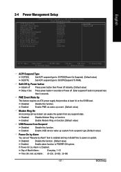
...-On by Alarm" item to enabled and key in Date/Time to power on function.(Default value) USB Resume from Suspend Disabled Disable this function. BIOS Setup Disabled Disable this function. Disabled Disable this function. (Default value) Enabled Enable alarm function to POWER ON system. Enabled Enable USB device wake up...
...-On by Alarm" item to enabled and key in Date/Time to power on function.(Default value) USB Resume from Suspend Disabled Disable this function. BIOS Setup Disabled Disable this function. Disabled Disable this function. (Default value) Enabled Enable alarm function to POWER ON system. Enabled Enable USB device wake up...
Manual
Page 43
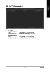
... 2 IRQ Assignment Auto 3,4,5,7,9,10,11,12,14,15 Auto assign IRQ to PCI 1. (Default value) Set IRQ 3,4,5,7,9,10,11,12,14,15 to PCI 2. - 43 - BIOS Setup
... 2 IRQ Assignment Auto 3,4,5,7,9,10,11,12,14,15 Auto assign IRQ to PCI 1. (Default value) Set IRQ 3,4,5,7,9,10,11,12,14,15 to PCI 2. - 43 - BIOS Setup


