Manual
Page 10
... dual channel DDRII 800/667/533/400 DIMMs Š Supports 1.8V DDRII DIMMs Expanstion Slots Š 1 PCI Express x 16 slot Š 1 PCI Express x 1 slot Š 2 PCI slots Internal Connectors Š 1 24-pin ATX power connector Š 1 4-pin ATX 12V power connector Š 1 floppy connector Š 2 IDE connectors Š 4 SATA 3Gb/s connectors Š 1 CPU fan connector Š 1 system fan connector Š 1 front panel connector Š 1 front audio connector Š 1 CD In connector Š 2 USB 2.0/1.1 connectors for additional 4 USB 2.0/1.1 ports by cable GA-M51GM-S2G...
... dual channel DDRII 800/667/533/400 DIMMs Š Supports 1.8V DDRII DIMMs Expanstion Slots Š 1 PCI Express x 16 slot Š 1 PCI Express x 1 slot Š 2 PCI slots Internal Connectors Š 1 24-pin ATX power connector Š 1 4-pin ATX 12V power connector Š 1 floppy connector Š 2 IDE connectors Š 4 SATA 3Gb/s connectors Š 1 CPU fan connector Š 1 system fan connector Š 1 front panel connector Š 1 front audio connector Š 1 CD In connector Š 2 USB 2.0/1.1 connectors for additional 4 USB 2.0/1.1 ports by cable GA-M51GM-S2G...
Manual
Page 18
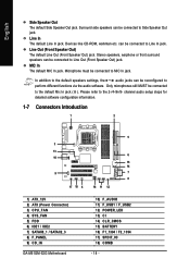
... audio software. can be connected to the default Mic In jack ( ). Microphone must be connected to Line In jack. channel audio setup steps for detailed software configuration information. 1-7 Connectors Introduction 1 2 5 3 13 6 10 15 14 9 7 8 17 18 4 16 11 12 1) ATX_12V 2) ATX (Power Connector) 3) CPU_FAN 4) SYS_FAN 5) FDD 6) IDE1 / IDE2 7) SATAII0_1 / SATAII2_3 8) F_PANEL 9) CD_IN GA-M51GM-S2G Motherboard 10) F_AUDIO 11) F_USB1 / F_USB2 12) POWER_LED 13) CI 14) CLR_CMOS 15) BATTERY...
... audio software. can be connected to the default Mic In jack ( ). Microphone must be connected to Line In jack. channel audio setup steps for detailed software configuration information. 1-7 Connectors Introduction 1 2 5 3 13 6 10 15 14 9 7 8 17 18 4 16 11 12 1) ATX_12V 2) ATX (Power Connector) 3) CPU_FAN 4) SYS_FAN 5) FDD 6) IDE1 / IDE2 7) SATAII0_1 / SATAII2_3 8) F_PANEL 9) CD_IN GA-M51GM-S2G Motherboard 10) F_AUDIO 11) F_USB1 / F_USB2 12) POWER_LED 13) CI 14) CLR_CMOS 15) BATTERY...
Manual
Page 20
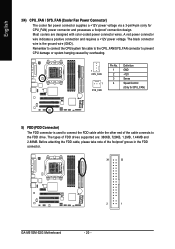
... to connect the CPU/system fan cable to the CPU_FAN/SYS_FAN connector to prevent CPU damage or system hanging caused by overheating. 1 CPU_FAN 1 SYS_FAN Pin No. 1 2 3 4 Definition GND +12V Sense Speed Control (Only for CPU_FAN) power connector and possesses a foolproof connection design. The black connector wire is used to connect the FDD cable while the other end of the foolproof groove in the FDD connector. 34 33 2 1 GA-M51GM-S2G Motherboard - 20...
... to connect the CPU/system fan cable to the CPU_FAN/SYS_FAN connector to prevent CPU damage or system hanging caused by overheating. 1 CPU_FAN 1 SYS_FAN Pin No. 1 2 3 4 Definition GND +12V Sense Speed Control (Only for CPU_FAN) power connector and possesses a foolproof connection design. The black connector wire is used to connect the FDD cable while the other end of the foolproof groove in the FDD connector. 34 33 2 1 GA-M51GM-S2G Motherboard - 20...
Manual
Page 22
...LED/ Power/ Sleep LED Speaker Connector Power Switch MSG+ MSG- Definition 1 CD-L 2 GND 3 GND 4 CD-R GA-M51GM-S2G Motherboard - 22 - Pin 3: NC Pin 4: Data(-) Open: Normal Close: Reset Hardware System Open: Normal Close: Power On/Off Pin 1: LED anode(+) Pin 2: LED cathode(-) NC 9) CD_IN (CD In Connector) Connect CD-ROM or DVD-ROM audio out to the pin assignment below. RESRES+ NC HD (IDE Hard Disk Active LED) SPEAK (Speaker Connector) RES (Reset Switch) PW (Power Switch) MSG(Message LED/Power/Sleep LED) NC Reset Switch IDE Hard Disk Active LED Pin 1: LED anode(+) Pin 2: LED...
...LED/ Power/ Sleep LED Speaker Connector Power Switch MSG+ MSG- Definition 1 CD-L 2 GND 3 GND 4 CD-R GA-M51GM-S2G Motherboard - 22 - Pin 3: NC Pin 4: Data(-) Open: Normal Close: Reset Hardware System Open: Normal Close: Power On/Off Pin 1: LED anode(+) Pin 2: LED cathode(-) NC 9) CD_IN (CD In Connector) Connect CD-ROM or DVD-ROM audio out to the pin assignment below. RESRES+ NC HD (IDE Hard Disk Active LED) SPEAK (Speaker Connector) RES (Reset Switch) PW (Power Switch) MSG(Message LED/Power/Sleep LED) NC Reset Switch IDE Hard Disk Active LED Pin 1: LED anode(+) Pin 2: LED...
Manual
Page 30
... reset to the default for your motherboard. GA-M51GM-S2G Motherboard - 30 - English : For Boot Menu Select boot sequence for onboard (or add-on the screen. Award Modular BIOS v6.00PG, An Energy Star Ally Copyright (C) 1984-2005, Award Software, Inc. If you can't find the setting you enter Award BIOS CMOS Setup Utility, the Main Menu (as usual. Boot Menu == Select a Boot First device == Floppy LS120 Hard Disk CDROM ZIP USB-FDD USB-ZIP USB-CDROM USB-HDD Legacy LAN KL:Move Enter :Accept ESC:Exit The Main Menu (For example: BIOS...
... reset to the default for your motherboard. GA-M51GM-S2G Motherboard - 30 - English : For Boot Menu Select boot sequence for onboard (or add-on the screen. Award Modular BIOS v6.00PG, An Energy Star Ally Copyright (C) 1984-2005, Award Software, Inc. If you can't find the setting you enter Award BIOS CMOS Setup Utility, the Main Menu (as usual. Boot Menu == Select a Boot First device == Floppy LS120 Hard Disk CDROM ZIP USB-FDD USB-ZIP USB-CDROM USB-HDD Legacy LAN KL:Move Enter :Accept ESC:Exit The Main Menu (For example: BIOS...
Manual
Page 32
... IDE devices are : CHS/LBA/Large/Auto(default:Auto) GA-M51GM-S2G Motherboard - 32 - to Dec. Week The week, from Sun to set the access mode for automatic device detection. Through Dec. The time is 13:00:00. IDE Channel 0 Master, Slave, IDE Channel 1 Master, Slave IDE HDD Auto-Detection Press "Enter" to select this to Sat, determined by the BIOS and is , , , . IDE Device Setup. You can manually input the correct settings Access Mode Use this option for the hard drive. time clock...
... IDE devices are : CHS/LBA/Large/Auto(default:Auto) GA-M51GM-S2G Motherboard - 32 - to Dec. Week The week, from Sun to set the access mode for automatic device detection. Through Dec. The time is 13:00:00. IDE Channel 0 Master, Slave, IDE Channel 1 Master, Slave IDE HDD Auto-Detection Press "Enter" to select this to Sat, determined by the BIOS and is , , , . IDE Device Setup. You can manually input the correct settings Access Mode Use this option for the hard drive. time clock...
Manual
Page 35
... it down the list. Hard Disk Select your boot device priority by Hard Disk. CDROM Select your boot device priority by CDROM. USB-CDROM Select your boot device priority by USB-FDD. Disabled BIOS will not search for the type of floppy disk drive by USB-CDROM. USB-FDD Select your boot device priority by track number. English 2-2 Advanced BIOS Features CMOS Setup Utility-Copyright (C) 1984-2006 Award Software Advanced BIOS Features ` Hard Disk Boot Priority First Boot Device Second Boot Device Third Boot Device Boot Up Floopy Seek Password Check HDD S.M.A.R.T.
... it down the list. Hard Disk Select your boot device priority by Hard Disk. CDROM Select your boot device priority by CDROM. USB-CDROM Select your boot device priority by USB-FDD. Disabled BIOS will not search for the type of floppy disk drive by USB-CDROM. USB-FDD Select your boot device priority by track number. English 2-2 Advanced BIOS Features CMOS Setup Utility-Copyright (C) 1984-2006 Award Software Advanced BIOS Features ` Hard Disk Boot Priority First Boot Device Second Boot Device Third Boot Device Boot Up Floopy Seek Password Check HDD S.M.A.R.T.
Manual
Page 36
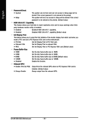
... onboard GPU. Set Init Display First to PCI VGA card. Disabled Disable this function. The system will boot, but access to Setup will be denied if the correct password is not entered at the prompt. Disabled Disabled HDD S.M.A.R.T. capability.(Default value) Init Display First This feature allows you to select the first initiation of the monitor display from the onboard GPU when no PCI Express VGA card is installed. GA-M51GM-S2G Motherboard - 36 - PCI Slot Onboard VGA Set Init Display First to onboard VGA. Set On-chip frame buffer size...
... onboard GPU. Set Init Display First to PCI VGA card. Disabled Disable this function. The system will boot, but access to Setup will be denied if the correct password is not entered at the prompt. Disabled Disabled HDD S.M.A.R.T. capability.(Default value) Init Display First This feature allows you to select the first initiation of the monitor display from the onboard GPU when no PCI Express VGA card is installed. GA-M51GM-S2G Motherboard - 36 - PCI Slot Onboard VGA Set Init Display First to onboard VGA. Set On-chip frame buffer size...
Manual
Page 47
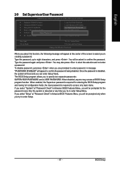
... to confirm the password being disabled. Type the password, up to enter Setup Menu. To disable password, just press when you in Advance BIOS Features Menu, you will be asked to confirm the password. English 2-9 Set Supervisor/User Password CMOS Setup Utility-Copyright (C) 1984-2006 Award Software ` Standard CMOS Features ` Advanced BIOS Features ` Integrated Peripherals ` Power Management Setup ` PnP/PCI ConfiguratioEnsnter Password: ` PC Health Status Load Fail-Safe Defaults Load Optimized Defaults Set Supervisor Password Set User Password Save & Exit Setup Exit Without Saving...
... to confirm the password being disabled. Type the password, up to enter Setup Menu. To disable password, just press when you in Advance BIOS Features Menu, you will be asked to confirm the password. English 2-9 Set Supervisor/User Password CMOS Setup Utility-Copyright (C) 1984-2006 Award Software ` Standard CMOS Features ` Advanced BIOS Features ` Integrated Peripherals ` Power Management Setup ` PnP/PCI ConfiguratioEnsnter Password: ` PC Health Status Load Fail-Safe Defaults Load Optimized Defaults Set Supervisor Password Set User Password Save & Exit Setup Exit Without Saving...
Manual
Page 54
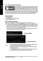
... executed from CD/DVD: Press any key to enter Xpress Recovery2. GA-M51GM-S2G Motherboard - 54 - Save the settings and exit the BIOS Setup. Upon system restart, the message which says "Boot from CD-ROM. Insert the provided driver CD into your hard disk. English 4-1-2 Xpress Recovery2 Introduction Xpress Recovery2 is able to back up data on hard disks on . . . Supporting Microsoft operating systems including Windows XP/2000/NT...
... executed from CD/DVD: Press any key to enter Xpress Recovery2. GA-M51GM-S2G Motherboard - 54 - Save the settings and exit the BIOS Setup. Upon system restart, the message which says "Boot from CD-ROM. Insert the provided driver CD into your hard disk. English 4-1-2 Xpress Recovery2 Introduction Xpress Recovery2 is able to back up data on hard disks on . . . Supporting Microsoft operating systems including Windows XP/2000/NT...
Manual
Page 57
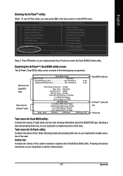
...the Q-Flash/Dual BIOS utility. Blocking a task and pressing Enter key on your keyboard to enable execution of the task. CMOS Setup Utility-Copyright (C) 1984-2004 Award Software Standard CMOS Features Advanced BIOS Features Integrated Peripherals Power Management Setup PnP/PCI Configurations PC Health Status MB Intelligent Tweaker(M.I.T.) ESC: Quit F8: Dual BIOS/Q-Flash Select Language Load Fail-Safe Defaults Load Optimized Defaults Set Supervisor Password Set User Password Save & Exit Setup Exit Without Saving F3: Change Language F10: Save & Exit Setup Time, Date, Hard Disk Type... Step...
...the Q-Flash/Dual BIOS utility. Blocking a task and pressing Enter key on your keyboard to enable execution of the task. CMOS Setup Utility-Copyright (C) 1984-2004 Award Software Standard CMOS Features Advanced BIOS Features Integrated Peripherals Power Management Setup PnP/PCI Configurations PC Health Status MB Intelligent Tweaker(M.I.T.) ESC: Quit F8: Dual BIOS/Q-Flash Select Language Load Fail-Safe Defaults Load Optimized Defaults Set Supervisor Password Set User Password Save & Exit Setup Exit Without Saving F3: Change Language F10: Save & Exit Setup Time, Date, Hard Disk Type... Step...
Manual
Page 65
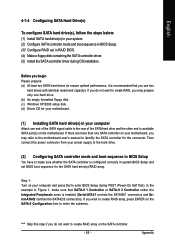
...use two hard drives with identical model and capacity). Step 1: Turn on your computer and press Del to available SATA port(s) on your power supply to the hard drive. (2) Configuring SATA controller mode and boot sequence in BIOS Setup You have to create RAID array on the SATA-II Configuration item to ensure optimal performance, it is enabled (Serial-ATAII1 controls the SATAII0/1 connectors and Serial-ATAII2 controls the SATAII2/3 connectors). Appendix English 4-1-4 Configuring SATA Hard Drive(s) To configure SATA hard drive(s), follow the steps below: (1) Install SATA hard drive...
...use two hard drives with identical model and capacity). Step 1: Turn on your computer and press Del to available SATA port(s) on your power supply to the hard drive. (2) Configuring SATA controller mode and boot sequence in BIOS Setup You have to create RAID array on the SATA-II Configuration item to ensure optimal performance, it is enabled (Serial-ATAII1 controls the SATAII0/1 connectors and Serial-ATAII2 controls the SATAII2/3 connectors). Appendix English 4-1-4 Configuring SATA Hard Drive(s) To configure SATA hard drive(s), follow the steps below: (1) Install SATA hard drive...
Manual
Page 72
...-DOS mode(Note1). Figure 12 Figure 13 (Note 1) For users without a startup disk: Use an alternative system and insert the GIGABYTE motherboard driver CD-ROM. A command prompt window will then automatically zip and transfer this driver file to install the SATA controller driver during the Windows setup process. Boot from the menu in Figure 13. Press ENTER after each command (Figure 12): cd bootdrv menu Step 2: When the controller menu (Figure 13) appears, remove...
...-DOS mode(Note1). Figure 12 Figure 13 (Note 1) For users without a startup disk: Use an alternative system and insert the GIGABYTE motherboard driver CD-ROM. A command prompt window will then automatically zip and transfer this driver file to install the SATA controller driver during the Windows setup process. Boot from the menu in Figure 13. Press ENTER after each command (Figure 12): cd bootdrv menu Step 2: When the controller menu (Figure 13) appears, remove...
Manual
Page 73
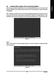
...-ROM drives, or special disk controllers for use with Windows, including those for which you have any device support disks from a mass storage device manufacturer, press S. * If you see the next screen. Windows Setup Press F6 if you need to manually specify an adapter. Appendix Figure 15 Step 2: When a screen similar to that you have prepared the SATA driver disk and configured BIOS settings, you have chosen to install a 3rd party SCSI or RAID driver. Windows Setup Setup...
...-ROM drives, or special disk controllers for use with Windows, including those for which you have any device support disks from a mass storage device manufacturer, press S. * If you see the next screen. Windows Setup Press F6 if you need to manually specify an adapter. Appendix Figure 15 Step 2: When a screen similar to that you have prepared the SATA driver disk and configured BIOS settings, you have chosen to install a 3rd party SCSI or RAID driver. Windows Setup Setup...
Manual
Page 76
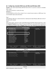
... Windows 2000 with Service Pack 2 (or previous versions) to a RAID array. Solutions 1: Use the NVRAID tool (nForce Driver Version 5.xx) to convert the boot volume to a bootable RAID volume. Step 2: After system restarts, press Del to resolve this issue. Here are two solutions to enter system BIOS Setup during POST (Power-On Self Test). CMOS Setup Utility-Copyright (C) 1984-2006 Award Software Integrated Peripherals IDE Configuration USB Configuration SATA-II Configuration Onboard Audio Function Onboard LAN Function Onboard LAN Boot ROM Onboard 1394 Function Onboard Serial Port...
... Windows 2000 with Service Pack 2 (or previous versions) to a RAID array. Solutions 1: Use the NVRAID tool (nForce Driver Version 5.xx) to convert the boot volume to a bootable RAID volume. Step 2: After system restarts, press Del to resolve this issue. Here are two solutions to enter system BIOS Setup during POST (Power-On Self Test). CMOS Setup Utility-Copyright (C) 1984-2006 Award Software Integrated Peripherals IDE Configuration USB Configuration SATA-II Configuration Onboard Audio Function Onboard LAN Function Onboard LAN Boot ROM Onboard 1394 Function Onboard Serial Port...
Manual
Page 83
... the possible computer problems. However, they are hidden in new BIOS version. Press Del to the battery holder. 5. AWARD BIOS Beep Codes 1 short: System boots successfully 2 short: CMOS setting error 1 long 1 short: DRAM or M/B error 1 long 2 short: Monitor or display card error 1 long 3 short: Keyboard error 1 long 9 short: BIOS ROM error Continuous long beeps: DRAM error Continuous short beeps: Power error - 83 - Question 4: Why do I hear different continuous beeps from computer after turning up . If not, please change another speaker with an internal amplifier. The situations...
... the possible computer problems. However, they are hidden in new BIOS version. Press Del to the battery holder. 5. AWARD BIOS Beep Codes 1 short: System boots successfully 2 short: CMOS setting error 1 long 1 short: DRAM or M/B error 1 long 2 short: Monitor or display card error 1 long 3 short: Keyboard error 1 long 9 short: BIOS ROM error Continuous long beeps: DRAM error Continuous short beeps: Power error - 83 - Question 4: Why do I hear different continuous beeps from computer after turning up . If not, please change another speaker with an internal amplifier. The situations...
Manual
Page 3
CMOS Setup Utility-Copyright (C) 1984-2005 Award Software Integrated Peripherals } SATAII RAID Config On-Chip IDE Channel0 [Press Enter] [Enabled] Item Help Menu Level} On-Chip IDE Channel1 [Enabled] IDE1 Conductor Cable [Auto] IDE2 Conductor Cable Serial-ATA-II 1 Serial-ATA-II 2 [Auto] [Enabled] [Enabled] On-Chip USB [V1.1+V2.0] USB Keyboard Support [Disabled] USB Mouse Support [Disabled] Onboard Audio Function Onboard LAN Function Onboard LAN Boot ROM [Auto] [Auto] [Disabled] Onboard 1394 Function [Enabled] Onboard Serial Port 1 [3F8/IRQ4] Onboard Parallel Port [378/...
CMOS Setup Utility-Copyright (C) 1984-2005 Award Software Integrated Peripherals } SATAII RAID Config On-Chip IDE Channel0 [Press Enter] [Enabled] Item Help Menu Level} On-Chip IDE Channel1 [Enabled] IDE1 Conductor Cable [Auto] IDE2 Conductor Cable Serial-ATA-II 1 Serial-ATA-II 2 [Auto] [Enabled] [Enabled] On-Chip USB [V1.1+V2.0] USB Keyboard Support [Disabled] USB Mouse Support [Disabled] Onboard Audio Function Onboard LAN Function Onboard LAN Boot ROM [Auto] [Auto] [Disabled] Onboard 1394 Function [Enabled] Onboard Serial Port 1 [3F8/IRQ4] Onboard Parallel Port [378/...
Manual
Page 9
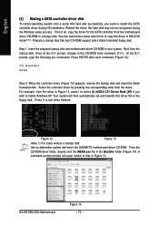
... the motherboard driver CD into the CD-ROM drive. The installation utility will appear automatically. Quit the installation utility first. Figure 12 Step 3: Go to My Computer and right-click the CD-ROM drive icon and select Open (Figure 12). The instructions below explain how to install required driver for the SATA controller from the motherboard driver CD to a floppy disk. SATA Configurations (Nvidia nForce430) (4) Making a SATA controller driver disk To install Windows 2000/XP onto a SATA hard drive/RAID array...
... the motherboard driver CD into the CD-ROM drive. The installation utility will appear automatically. Quit the installation utility first. Figure 12 Step 3: Go to My Computer and right-click the CD-ROM drive icon and select Open (Figure 12). The instructions below explain how to install required driver for the SATA controller from the motherboard driver CD to a floppy disk. SATA Configurations (Nvidia nForce430) (4) Making a SATA controller driver disk To install Windows 2000/XP onto a SATA hard drive/RAID array...
Manual
Page 11
... to install Windows 2000/XP onto your SATA hard drive with Windows, including those for the following is an example of Windows XP installation. Figure 15 Step 2: When a screen similar to that you have chosen to manually specify an adapter. Windows Setup Setup could not determine the type of some files being loaded before you are ready to specify additional mass storage devices for use with the driver. Currently, Setup will...
... to install Windows 2000/XP onto your SATA hard drive with Windows, including those for the following is an example of Windows XP installation. Figure 15 Step 2: When a screen similar to that you have chosen to manually specify an adapter. Windows Setup Setup could not determine the type of some files being loaded before you are ready to specify additional mass storage devices for use with the driver. Currently, Setup will...
Manual
Page 14
... Defaults Download and install Windows 2000 Service Pack 4 from Microsoft's website. CMOS Setup Utility-Copyright (C) 1984-2005 Award Software Integrated Peripherals } SATAII RAID Config On-Chip IDE Channel0 On-Chip IDE Channel1 IDE1 Conductor Cable [Press Enter] [Enabled] [Enabled] [Auto] Item Help Menu Level} IDE2 Conductor Cable [Auto] Serial-ATA-II 1 [Enabled] Serial-ATA-II 2 [Enabled] On-Chip USB USB Keyboard Support USB Mouse Support [V1.1+V2.0] [Disabled] [Disabled] Onboard Audio Function [Auto] Onboard LAN Function [Auto] Onboard LAN Boot ROM [Disabled] Onboard...
... Defaults Download and install Windows 2000 Service Pack 4 from Microsoft's website. CMOS Setup Utility-Copyright (C) 1984-2005 Award Software Integrated Peripherals } SATAII RAID Config On-Chip IDE Channel0 On-Chip IDE Channel1 IDE1 Conductor Cable [Press Enter] [Enabled] [Enabled] [Auto] Item Help Menu Level} IDE2 Conductor Cable [Auto] Serial-ATA-II 1 [Enabled] Serial-ATA-II 2 [Enabled] On-Chip USB USB Keyboard Support USB Mouse Support [V1.1+V2.0] [Disabled] [Disabled] Onboard Audio Function [Auto] Onboard LAN Function [Auto] Onboard LAN Boot ROM [Disabled] Onboard...


