Manual
Page 10
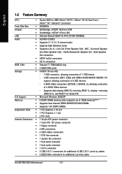
...138; 4 SATA 3Gb/s connectors Š 1 CPU fan connector Š 1 system fan connector Š 1 front panel connector Š 1 front audio connector Š 1 CD In connector Š 2 USB 2.0/1.1 connectors for additional 4 USB 2.0/1.1 ports by cable GA-M51GM-S2G Motherboard - 10 - Side Speaker Out connection ...FDD connector, allowing connection of 1 FDD device - 2 IDE connectors (IDE1, IDE2) with UDMA 33/ATA 66/ATA 100/ATA 133 support, allowing connection of 4 IDE devices - 4 SATA 3Gb/s connectors (SATAII0_1,SATAII2_3), allowing connection of 4 SATA 3Gb/s devices - Surround ...
...138; 4 SATA 3Gb/s connectors Š 1 CPU fan connector Š 1 system fan connector Š 1 front panel connector Š 1 front audio connector Š 1 CD In connector Š 2 USB 2.0/1.1 connectors for additional 4 USB 2.0/1.1 ports by cable GA-M51GM-S2G Motherboard - 10 - Side Speaker Out connection ...FDD connector, allowing connection of 1 FDD device - 2 IDE connectors (IDE1, IDE2) with UDMA 33/ATA 66/ATA 100/ATA 133 support, allowing connection of 4 IDE devices - 4 SATA 3Gb/s connectors (SATAII0_1,SATAII2_3), allowing connection of 4 SATA 3Gb/s devices - Surround ...
Manual
Page 11
.../Subwoofer Speaker Out/Side Speaker Out) I/O Control Š IT8716 chip Hardware Monitor Š System voltage detection Š CPU / System temperature detection Š CPU / System fan speed detection Š CPU warning temperature Š CPU / System fan failure warning Š Supports CPU / System Smart Fan function(Note 2) BIOS Š 1 4Mbit flash ROM Š Use of licensed AWARD BIOS...
.../Subwoofer Speaker Out/Side Speaker Out) I/O Control Š IT8716 chip Hardware Monitor Š System voltage detection Š CPU / System temperature detection Š CPU / System fan speed detection Š CPU warning temperature Š CPU / System fan failure warning Š Supports CPU / System Smart Fan function(Note 2) BIOS Š 1 4Mbit flash ROM Š Use of licensed AWARD BIOS...
Manual
Page 12
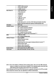
...direction of the CPU. 3. If this occurs, please change the positioning of the CPU. Fig.2 Pin 1 location on the CPU by a small triangle that the motherboard supports the CPU. 2. Align the CPU to the unlocked position as shown in the wrong direction, the CPU will not fit... the CPU, graphics card, memory, hard drive, etc. 1-3-1 Installation of the CPU Check the CPU pins to system use extra care when installing the CPU. If you install the CPU in Fig. 2. GA-M51GM-S2G Motherboard - 12 - English 1-3 Installation of the CPU and CPU Cooler Before installing the CPU, please...
...direction of the CPU. 3. If this occurs, please change the positioning of the CPU. Fig.2 Pin 1 location on the CPU by a small triangle that the motherboard supports the CPU. 2. Align the CPU to the unlocked position as shown in the wrong direction, the CPU will not fit... the CPU, graphics card, memory, hard drive, etc. 1-3-1 Installation of the CPU Check the CPU pins to system use extra care when installing the CPU. If you install the CPU in Fig. 2. GA-M51GM-S2G Motherboard - 12 - English 1-3 Installation of the CPU and CPU Cooler Before installing the CPU, please...
Manual
Page 15
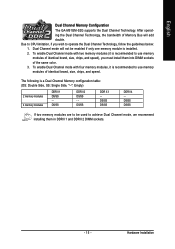
Due to CPU limitation, if you must install them in DDRII 1 and DDRII 2 DIMM sockets. - 15 - The following is installed. 2. DS/SS DS/SS If two memory modules are to use memory modules of the same color. 3. English Dual Channel Memory Configuration The GA-M51GM-S2G supports the Dual Channel Technology. Dual Channel mode will add...
Due to CPU limitation, if you must install them in DDRII 1 and DDRII 2 DIMM sockets. - 15 - The following is installed. 2. DS/SS DS/SS If two memory modules are to use memory modules of the same color. 3. English Dual Channel Memory Configuration The GA-M51GM-S2G supports the Dual Channel Technology. Dual Channel mode will add...
Manual
Page 20
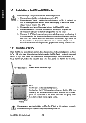
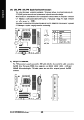
... of FDD drives supported are designed with color-coded power connector wires. Remember to connect the CPU/system fan cable to the CPU_FAN/SYS_FAN connector to connect the FDD cable while the other end of the foolproof groove in the FDD connector. 34 33 2 1 GA-M51GM-S2G Motherboard - 20 ... 3-pin/4-pin (only for CPU_FAN) 5) FDD (FDD Connector) The FDD connector is the ground wire (GND). The black connector wire is used to prevent CPU damage or system hanging caused by overheating. 1 CPU_FAN 1 SYS_FAN Pin No. 1 2 3 4 Definition GND +12V Sense Speed Control (Only for CPU_FAN) ...
... of FDD drives supported are designed with color-coded power connector wires. Remember to connect the CPU/system fan cable to the CPU_FAN/SYS_FAN connector to connect the FDD cable while the other end of the foolproof groove in the FDD connector. 34 33 2 1 GA-M51GM-S2G Motherboard - 20 ... 3-pin/4-pin (only for CPU_FAN) 5) FDD (FDD Connector) The FDD connector is the ground wire (GND). The black connector wire is used to prevent CPU damage or system hanging caused by overheating. 1 CPU_FAN 1 SYS_FAN Pin No. 1 2 3 4 Definition GND +12V Sense Speed Control (Only for CPU_FAN) ...
Manual
Page 45
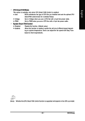
... speed with Easy Tune based on their requirements. (Note) Whether the CPU Smart FAN Control function is enabled. English CPU Smart FAN Mode This option is available only when CPU Smart FAN Control is supported will run at different speed depending on system temperature. System Smart FAN ...Control Disabled Disable this function. (Default value) Enabled When this function is enabled, system fan will depend on the CPU you install. - 45 -...
... speed with Easy Tune based on their requirements. (Note) Whether the CPU Smart FAN Control function is enabled. English CPU Smart FAN Mode This option is available only when CPU Smart FAN Control is supported will run at different speed depending on system temperature. System Smart FAN ...Control Disabled Disable this function. (Default value) Enabled When this function is enabled, system fan will depend on the CPU you install. - 45 -...

