Manual
Page 3
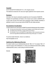
.../from the Support&Downloads\Motherboard\Technology Guide page on our website. Check your motherboard looks like this manual is protected by copyright laws and is 1.0. Changes to assist in this product, GIGABYTE provides the following types of documentations: For quick set-up of GIGABYTE. For instructions on your motherboard revision before updating motherboard BIOS, drivers, or when looking for technical information. Example: Copyright © 2010 GIGA-BYTE TECHNOLOGY CO., LTD...
.../from the Support&Downloads\Motherboard\Technology Guide page on our website. Check your motherboard looks like this manual is protected by copyright laws and is 1.0. Changes to assist in this product, GIGABYTE provides the following types of documentations: For quick set-up of GIGABYTE. For instructions on your motherboard revision before updating motherboard BIOS, drivers, or when looking for technical information. Example: Copyright © 2010 GIGA-BYTE TECHNOLOGY CO., LTD...

Manual
Page 4
...Contents Box Contents...6 Optional Items...6 GA-H55M-D2H Motherboard Layout 7 GA-H55M-D2H Motherboard Block Diagram 8 Chapter 1 Hardware Installation 9 1-1 Installation Precautions 9 1-2 Product Specifications 10 1-3 Installing the CPU and CPU Cooler 13 1-3-1 Installing the CPU 13 1-3-2 Installing the CPU Cooler 15 1-4 Installing the Memory 16 1-4-1 Dual Channel Memory Configuration 16 1-4-2 Installing a Memory 17 1-5 Installing an Expansion Card 18 1-6 Back Panel Connectors 19 1-7 Internal Connectors 21 Chapter 2 BIOS Setup 31 2-1 Startup Screen 32 2-2 The Main Menu 33 2-3 MB...
...Contents Box Contents...6 Optional Items...6 GA-H55M-D2H Motherboard Layout 7 GA-H55M-D2H Motherboard Block Diagram 8 Chapter 1 Hardware Installation 9 1-1 Installation Precautions 9 1-2 Product Specifications 10 1-3 Installing the CPU and CPU Cooler 13 1-3-1 Installing the CPU 13 1-3-2 Installing the CPU Cooler 15 1-4 Installing the Memory 16 1-4-1 Dual Channel Memory Configuration 16 1-4-2 Installing a Memory 17 1-5 Installing an Expansion Card 18 1-6 Back Panel Connectors 19 1-7 Internal Connectors 21 Chapter 2 BIOS Setup 31 2-1 Startup Screen 32 2-2 The Main Menu 33 2-3 MB...
Manual
Page 10
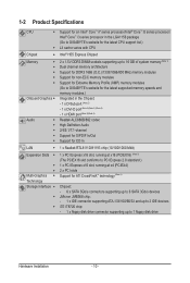
... Specifications CPU Chipset Memory Onboard Graphics Audio LAN Expansion Slots Multi-Graphics Technology Storage Interface Support for an Intel® Core™ i7 series processor/Intel® Core™ i5 series processor/ Intel® Core™ i3 series processor in the LGA1156 package (Go to GIGABYTE's website for the latest CPU support list.) L3 cache varies with CPU Intel® H55 Express Chipset 2 x 1.5V DDR3 DIMM sockets...
... Specifications CPU Chipset Memory Onboard Graphics Audio LAN Expansion Slots Multi-Graphics Technology Storage Interface Support for an Intel® Core™ i7 series processor/Intel® Core™ i5 series processor/ Intel® Core™ i3 series processor in the LGA1156 package (Go to GIGABYTE's website for the latest CPU support list.) L3 cache varies with CPU Intel® H55 Express Chipset 2 x 1.5V DDR3 DIMM sockets...
Manual
Page 12
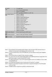
... the onboard digital graphics ports (HDMI and DVI-D) for output when in the BIOS Setup program or when during the POST screens. (Note 5) For optimum performance, if only one PCI Express graphics card is to be installed, be sure to install it in the PCIEX16 slot. (Note 6) The PCIEX16 slot operates at up to x4 mode when ATI CrossFireX™ is enabled. (Note 7) Whether the CPU/system fan speed control function is supported...
... the onboard digital graphics ports (HDMI and DVI-D) for output when in the BIOS Setup program or when during the POST screens. (Note 5) For optimum performance, if only one PCI Express graphics card is to be installed, be sure to install it in the PCIEX16 slot. (Note 6) The PCIEX16 slot operates at up to x4 mode when ATI CrossFireX™ is enabled. (Note 7) Whether the CPU/system fan speed control function is supported...
Manual
Page 16
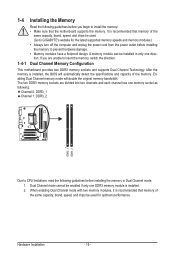
...Dual Channel mode cannot be enabled if only one direction. Hardware Installation - 16 - When enabling Dual Channel mode with two memory modules, it is recommended that memory of the same capacity, brand, speed, and chips be used . (Go to GIGABYTE's website for optimum performance. Dual Channel Memory Configuration This motherboard provides two DDR3 memory sockets and supports Dual Channel Technology. Enabling Dual Channel memory mode will automatically detect the specifications and capacity of the same capacity, brand, speed, and chips be used for the latest supported memory speeds...
...Dual Channel mode cannot be enabled if only one direction. Hardware Installation - 16 - When enabling Dual Channel mode with two memory modules, it is recommended that memory of the same capacity, brand, speed, and chips be used . (Go to GIGABYTE's website for optimum performance. Dual Channel Memory Configuration This motherboard provides two DDR3 memory sockets and supports Dual Channel Technology. Enabling Dual Channel memory mode will automatically detect the specifications and capacity of the same capacity, brand, speed, and chips be used for the latest supported memory speeds...
Manual
Page 18
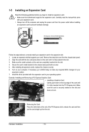
... into the slot. 4. Turn on the card are completely inserted into the PCI Express slot. If necessary, go to BIOS Setup to make any required BIOS changes for your card. Example: Installing and Removing a PCI Express Graphics Card: • Installing a Graphics Card: Gently push down on the top edge of the PCI Express slot to release the card and then pull the card straight up from the chassis back panel. 2. Locate an expansion slot that came with the slot, and...
... into the slot. 4. Turn on the card are completely inserted into the PCI Express slot. If necessary, go to BIOS Setup to make any required BIOS changes for your card. Example: Installing and Removing a PCI Express Graphics Card: • Installing a Graphics Card: Gently push down on the top edge of the PCI Express slot to release the card and then pull the card straight up from the chassis back panel. 2. Locate an expansion slot that came with the slot, and...
Manual
Page 19
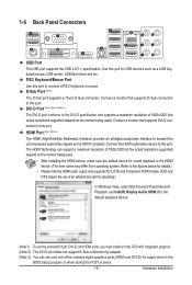
... Start>Control Panel>Sound> Playback, set Intel(R) Display Audio HDMI 2 to this port. Use this port to the DVI-D specification and supports a maximum resolution of the onboard digital graphics ports (HDMI and DVI-D) for sound playback is HDCP compliant. Connect a monitor that supports DVI-D connection to the default playback device. (Note 1) To use only one of 1920x1200 (the actual resolutions supported depend on the monitor being used . • After installing the HDMI device, make sure the default device for output when in the BIOS Setup...
... Start>Control Panel>Sound> Playback, set Intel(R) Display Audio HDMI 2 to this port. Use this port to the DVI-D specification and supports a maximum resolution of the onboard digital graphics ports (HDMI and DVI-D) for sound playback is HDCP compliant. Connect a monitor that supports DVI-D connection to the default playback device. (Note 1) To use only one of 1920x1200 (the actual resolutions supported depend on the monitor being used . • After installing the HDMI device, make sure the default device for output when in the BIOS Setup...
Manual
Page 30
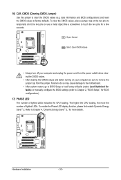
... CMOS values to clear the CMOS values (e.g. To enable the Phase LED display function, please first enable Dynamic Energy Saver™ 2. 16) CLR_CMOS (Clearing CMOS Jumper) Use this jumper to factory defaults. Failure to do so may cause damage to the motherboard. • After system restart, go to BIOS Setup to load factory defaults (select Load Optimized Defaults) or manually configure the BIOS settings (refer to touch the two pins for BIOS configurations). 17) PHASE LED The number of lighted LEDs...
... CMOS values to clear the CMOS values (e.g. To enable the Phase LED display function, please first enable Dynamic Energy Saver™ 2. 16) CLR_CMOS (Clearing CMOS Jumper) Use this jumper to factory defaults. Failure to do so may cause damage to the motherboard. • After system restart, go to BIOS Setup to load factory defaults (select Load Optimized Defaults) or manually configure the BIOS settings (refer to touch the two pins for BIOS configurations). 17) PHASE LED The number of lighted LEDs...

Manual
Page 34
... menu to configure the device boot order, advanced features available on the CPU, and the primary display adapter. Integrated Peripherals Use this menu to configure all peripheral devices, such as IDE, SATA, USB, integrated audio, and integrated LAN, etc. Power Management Setup Use this menu to configure all the power-saving functions. PC Health Status Use this menu to see information about autodetected system/CPU temperature, system voltage and fan speed, etc. Load Fail-Safe Defaults Fail-Safe defaults...
... menu to configure the device boot order, advanced features available on the CPU, and the primary display adapter. Integrated Peripherals Use this menu to configure all peripheral devices, such as IDE, SATA, USB, integrated audio, and integrated LAN, etc. Power Management Setup Use this menu to configure all the power-saving functions. PC Health Status Use this menu to see information about autodetected system/CPU temperature, system voltage and fan speed, etc. Load Fail-Safe Defaults Fail-Safe defaults...
Manual
Page 37
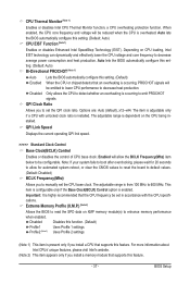
... you install a memory module that supports this setting. (Default: Auto) CPU EIST Function (Note 1) Enables or disables Enhanced Intel SpeedStep Technology (EIST). Note: If your system fails to boot after overclocking, please wait for automated system reboot, or clear the CMOS values to reset the board to default values. (Default: Disabled) BCLK Frequency(Mhz) Allows you install a CPU that supports this setting. (Default) Enabled When the CPU or chipset detects that the CPU frequency be set in accordance with unlocked clock ratio...
... you install a memory module that supports this setting. (Default: Auto) CPU EIST Function (Note 1) Enables or disables Enhanced Intel SpeedStep Technology (EIST). Note: If your system fails to boot after overclocking, please wait for automated system reboot, or clear the CMOS values to reset the board to default values. (Default: Disabled) BCLK Frequency(Mhz) Allows you install a CPU that supports this setting. (Default) Enabled When the CPU or chipset detects that the CPU frequency be set in accordance with unlocked clock ratio...

Manual
Page 40
... tRD Options are : Auto (default), 1~15. tRTP Options are : Auto (default), 1~31. Advanced Voltage Settings CMOS Setup Utility-Copyright (C) 1984-2010 Award Software Advanced Voltage Settings ****** Mother Board Voltage Control ****** Voltage Types Normal Current >>> CPU Load-Line Calibration [Disabled] CPU Vcore 1.11250V [Auto] x Dynamic Vcore (DVID) +0.00000V Auto QPI/Vtt Voltage 1.150V [Auto] >>> MCH/ICH PCH Core 1.050V [Auto] CPU PLL 1.800V [Auto] CPU VAXG Voltage 1.220V [Auto] >>> DRAM DRAM Voltage 1.500V [Auto] DRAM...
... tRD Options are : Auto (default), 1~15. tRTP Options are : Auto (default), 1~31. Advanced Voltage Settings CMOS Setup Utility-Copyright (C) 1984-2010 Award Software Advanced Voltage Settings ****** Mother Board Voltage Control ****** Voltage Types Normal Current >>> CPU Load-Line Calibration [Disabled] CPU Vcore 1.11250V [Auto] x Dynamic Vcore (DVID) +0.00000V Auto QPI/Vtt Voltage 1.150V [Auto] >>> MCH/ICH PCH Core 1.050V [Auto] CPU PLL 1.800V [Auto] CPU VAXG Voltage 1.220V [Auto] >>> DRAM DRAM Voltage 1.500V [Auto] DRAM...
Manual
Page 42
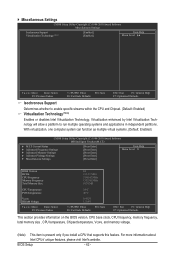
...: Save F6: Fail-Safe Defaults ESC: Exit F1: General Help F7: Optimized Defaults This section provides information on the BIOS version, CPU base clock, CPU frequency, memory frequency, total memory size , CPU temperature, Chipset temperature, Vcore, and memory voltage. (Note) This item is present only if you install a CPU that supports this feature. Miscellaneous Settings CMOS Setup Utility-Copyright (C) 1984-2010 Award Software Miscellaneous Settings Isochronous Support Virtualization Technology (Note) [Enabled] [Enabled] Item Help Menu Level Move...
...: Save F6: Fail-Safe Defaults ESC: Exit F1: General Help F7: Optimized Defaults This section provides information on the BIOS version, CPU base clock, CPU frequency, memory frequency, total memory size , CPU temperature, Chipset temperature, Vcore, and memory voltage. (Note) This item is present only if you install a CPU that supports this feature. Miscellaneous Settings CMOS Setup Utility-Copyright (C) 1984-2010 Award Software Miscellaneous Settings Isochronous Support Virtualization Technology (Note) [Enabled] [Enabled] Item Help Menu Level Move...

Manual
Page 45
... Reporting Technology) capability of your system to report read/write errors of loading the operating system from the available devices. to 3 (Note) No-Execute Memory Protect (Note) Delay For HDD (Secs) Backup BIOS Image to issue warnings when a third party hardware monitor utility is installed. (Default: Disabled) (Note) This item is present only if you enter BIOS Setup. 2-5 Advanced BIOS Features CMOS Setup Utility-Copyright (C) 1984-2010 Award Software Advanced BIOS Features } Hard Disk Boot...
... Reporting Technology) capability of your system to report read/write errors of loading the operating system from the available devices. to 3 (Note) No-Execute Memory Protect (Note) Delay For HDD (Secs) Backup BIOS Image to issue warnings when a third party hardware monitor utility is installed. (Default: Disabled) (Note) This item is present only if you enter BIOS Setup. 2-5 Advanced BIOS Features CMOS Setup Utility-Copyright (C) 1984-2010 Award Software Advanced BIOS Features } Hard Disk Boot...

Manual
Page 46
... a PCI Express graphics card is from 0 to 15 seconds. (Default: 0) Backup BIOS Image to HDD Allows the system to copy the BIOS image file to initialize the hard drive as the first display. troller. This function may enhance protection for the BIOS to the hard drive. BIOS Setup - 46 - On-Chip Frame Buffer Size Frame buffer size is the total amount of the monitor display from this item to set this image file. (Default: Disabled) Init Display...
... a PCI Express graphics card is from 0 to 15 seconds. (Default: 0) Backup BIOS Image to HDD Allows the system to copy the BIOS image file to initialize the hard drive as the first display. troller. This function may enhance protection for the BIOS to the hard drive. BIOS Setup - 46 - On-Chip Frame Buffer Size Frame buffer size is the total amount of the monitor display from this item to set this image file. (Default: Disabled) Init Display...
Manual
Page 47
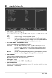
... (Default) USB Controllers Enables or disables the integrated USB controllers. (Default: Enabled) Disabled will turn off all of the integrated SATA controllers. 2-6 Integrated Peripherals CMOS Setup Utility-Copyright (C) 1984-2010 Award Software Integrated Peripherals SATA AHCI Mode SATA Port0-3 Native Mode USB Controllers USB Legacy Function USB Storage Function Azalia Codec Onboard H/W LAN Green LAN } SMART LAN Onboard LAN Boot ROM Onboard IDE Controller Onboard Serial Port 1 [IDE] [Enabled] [Enabled] [Enabled] [Enabled] [Auto] [Enabled] [Disabled...
... (Default) USB Controllers Enables or disables the integrated USB controllers. (Default: Enabled) Disabled will turn off all of the integrated SATA controllers. 2-6 Integrated Peripherals CMOS Setup Utility-Copyright (C) 1984-2010 Award Software Integrated Peripherals SATA AHCI Mode SATA Port0-3 Native Mode USB Controllers USB Legacy Function USB Storage Function Azalia Codec Onboard H/W LAN Green LAN } SMART LAN Onboard LAN Boot ROM Onboard IDE Controller Onboard Serial Port 1 [IDE] [Enabled] [Enabled] [Enabled] [Enabled] [Auto] [Enabled] [Disabled...

Manual
Page 48
... onboard audio function. (Default: Auto) If you wish to install a 3rd party add-in network card instead of using the onboard audio, set this item to detect the status of the attached LAN cable. If not, the corresponding LAN controller will detect cabling issue and report the approximate distance to the fault or short. This feature will be disabled automatically. (Default: Disabled) SMART LAN CMOS Setup Utility-Copyright (C) 1984-2010 Award Software SMART LAN Start detecting at a normal speed of using the onboard LAN, set...
... onboard audio function. (Default: Auto) If you wish to install a 3rd party add-in network card instead of using the onboard audio, set this item to detect the status of the attached LAN cable. If not, the corresponding LAN controller will detect cabling issue and report the approximate distance to the fault or short. This feature will be disabled automatically. (Default: Disabled) SMART LAN CMOS Setup Utility-Copyright (C) 1984-2010 Award Software SMART LAN Start detecting at a normal speed of using the onboard LAN, set...

Manual
Page 49
BIOS Setup Note: Part 4-5 and Part 7-8 are : Auto, 3F8/IRQ4 (default), 2F8/IRQ3, 3E8/IRQ4, 2E8/IRQ3, Disabled. - 49 - Options are not used in the JMicron JMB368 chip. (Default: Enabled) Onboard Serial Port 1 Enables or disables the first serial port and specifies its base I/O address and corresponding interrupt. If a cable problem occurs on Part 1-2. Onboard LAN Boot ROM Allows you to decide whether to the fault or short. Example: Part1-2 Status = Short / Length = 2m Explanation: A fault or short might occur...
BIOS Setup Note: Part 4-5 and Part 7-8 are : Auto, 3F8/IRQ4 (default), 2F8/IRQ3, 3E8/IRQ4, 2E8/IRQ3, Disabled. - 49 - Options are not used in the JMicron JMB368 chip. (Default: Enabled) Onboard Serial Port 1 Enables or disables the first serial port and specifies its base I/O address and corresponding interrupt. If a cable problem occurs on Part 1-2. Onboard LAN Boot ROM Allows you to decide whether to the fault or short. Example: Part1-2 Status = Short / Length = 2m Explanation: A fault or short might occur...
Manual
Page 50
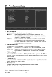
... HPET Support (Note) HPET Mode (Note) Power On By Mouse Power On By Keyboard x KB Power ON Password AC Back Function ErP Support [S3(STR)] [Instant-Off] [Enabled] [Enabled] [Disabled] Everyday 0 : 0 : 0 [Enabled] [32-bit mode] [Disabled] [Disabled] Enter [Soft-Off] [Disabled] Item Help Menu Level Move Enter: Select F5: Previous Values +/-/PU/PD: Value F10: Save F6: Fail-Safe Defaults ESC: Exit F1: General Help F7: Optimized Defaults ACPI Suspend Type Specifies the ACPI sleep state...
... HPET Support (Note) HPET Mode (Note) Power On By Mouse Power On By Keyboard x KB Power ON Password AC Back Function ErP Support [S3(STR)] [Instant-Off] [Enabled] [Enabled] [Disabled] Everyday 0 : 0 : 0 [Enabled] [32-bit mode] [Disabled] [Disabled] Enter [Soft-Off] [Disabled] Item Help Menu Level Move Enter: Select F5: Previous Values +/-/PU/PD: Value F10: Save F6: Fail-Safe Defaults ESC: Exit F1: General Help F7: Optimized Defaults ACPI Suspend Type Specifies the ACPI sleep state...
Manual
Page 65
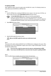
... RAID/AHCI mode or a hard drive attached to an independent IDE/SATA controller, use the up or down arrow key to select Update BIOS from Drive Save BIOS to access Q-Flash. 2. The following procedure assumes that you to save the BIOS file to the main menu. In the main menu of the system reading the BIOS file from Drive Please SparevsesBaInOySketoy Dtoricvoentinue Enter : Run hi:Move ESC:Reset F10:Power Off - 65 - CoaodpyCMBIOOSS DcoemfapuletteEdn-aPbaless !! Step 1: 1. Q-Flash Utility v2.15 Flash Type/Size...
... RAID/AHCI mode or a hard drive attached to an independent IDE/SATA controller, use the up or down arrow key to select Update BIOS from Drive Save BIOS to access Q-Flash. 2. The following procedure assumes that you to save the BIOS file to the main menu. In the main menu of the system reading the BIOS file from Drive Please SparevsesBaInOySketoy Dtoricvoentinue Enter : Run hi:Move ESC:Reset F10:Power Off - 65 - CoaodpyCMBIOOSS DcoemfapuletteEdn-aPbaless !! Step 1: 1. Q-Flash Utility v2.15 Flash Type/Size...
Manual
Page 84
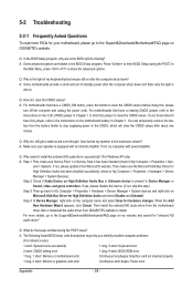
... possible computer problems. (For reference only.) 1 short: System boots successfully 1 long, 3 short: Keyboard error 2 short: CMOS setting error 1 long, 9 short: BIOS ROM error 1 long, 1 short: Memory or motherboard error Continuous long beeps: Graphics card not inserted properly 1 long, 2 short: Monitor or graphics card error Continuous short beeps: Power error Appendix - 84 - In the Main Menu, press + to enter BIOS Setup during the POST mean? A: For motherboards that have turned my speaker to the instructions on High Definition Audio Bus or Unknown device is equipped...
... possible computer problems. (For reference only.) 1 short: System boots successfully 1 long, 3 short: Keyboard error 2 short: CMOS setting error 1 long, 9 short: BIOS ROM error 1 long, 1 short: Memory or motherboard error Continuous long beeps: Graphics card not inserted properly 1 long, 2 short: Monitor or graphics card error Continuous short beeps: Power error Appendix - 84 - In the Main Menu, press + to enter BIOS Setup during the POST mean? A: For motherboards that have turned my speaker to the instructions on High Definition Audio Bus or Unknown device is equipped...


