Manual
Page 11
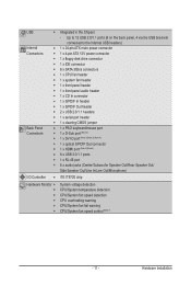
... USB headers) Internal w 1 x 24-pin ATX main power connector Connectors w 1 x 4-pin ATX 12V power connector w 1 x floppy disk drive connector w 1 x IDE connector w 6 x SATA 3Gb/s connectors w 1 x CPU fan header w 1 x system fan header w 1 x front panel header w 1 x front panel audio header w 1 x CD In connector w 1 x S/PDIF In header w 1 x S/PDIF Out header w 2 x USB 2.0/1.1 headers w 1 x serial port header w 1 x clearing CMOS...
... USB headers) Internal w 1 x 24-pin ATX main power connector Connectors w 1 x 4-pin ATX 12V power connector w 1 x floppy disk drive connector w 1 x IDE connector w 6 x SATA 3Gb/s connectors w 1 x CPU fan header w 1 x system fan header w 1 x front panel header w 1 x front panel audio header w 1 x CD In connector w 1 x S/PDIF In header w 1 x S/PDIF Out header w 2 x USB 2.0/1.1 headers w 1 x serial port header w 1 x clearing CMOS...
Manual
Page 12
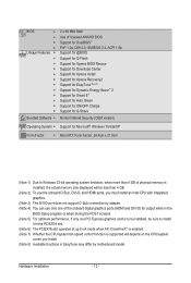
... memory size displayed will be less than 4 GB. (Note 2) To use the onboard D-Sub, DVI-D, and HDMI ports, you must install an Intel CPU with integrated graphics. (Note 3) The DVI-D port does not support D-Sub connection by adapter. (Note 4) You can use only one of the onboard digital... the PCIEX16 slot. (Note 6) The PCIEX16 slot operates at up to x4 mode when ATI CrossFireX™ is enabled. (Note 7) Whether the CPU/system fan speed control function is supported will depend on the CPU/system cooler you install. (Note 8) Available functions in EasyTune may differ by motherboard model.
... memory size displayed will be less than 4 GB. (Note 2) To use the onboard D-Sub, DVI-D, and HDMI ports, you must install an Intel CPU with integrated graphics. (Note 3) The DVI-D port does not support D-Sub connection by adapter. (Note 4) You can use only one of the onboard digital... the PCIEX16 slot. (Note 6) The PCIEX16 slot operates at up to x4 mode when ATI CrossFireX™ is enabled. (Note 7) Whether the CPU/system fan speed control function is supported will depend on the CPU/system cooler you install. (Note 8) Available functions in EasyTune may differ by motherboard model.

Manual
Page 15
...hear a "click" when pushing down on the push pins diagonally. Use extreme care when removing the CPU cooler because the thermal grease/tape between the CPU cooler and CPU may damage the CPU. - 15 - Hardware Installation Step 2: Before installing the cooler, note the direction of the arrow sign... Apply an even and thin layer of thermal grease on the surface of the CPU cooler to the CPU fan header (CPU_FAN) on the motherboard. Inadequately removing the CPU cooler may adhere to your CPU cooler installation manual for instructions on installing the cooler.) Step 5: After the installation...
...hear a "click" when pushing down on the push pins diagonally. Use extreme care when removing the CPU cooler because the thermal grease/tape between the CPU cooler and CPU may damage the CPU. - 15 - Hardware Installation Step 2: Before installing the cooler, note the direction of the arrow sign... Apply an even and thin layer of thermal grease on the surface of the CPU cooler to the CPU fan header (CPU_FAN) on the motherboard. Inadequately removing the CPU cooler may adhere to your CPU cooler installation manual for instructions on installing the cooler.) Step 5: After the installation...
Manual
Page 23
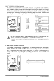
...2 +12V / Speed Control 3 Sense 4 Reserve • Be sure to connect fan cables to the fan headers to connect it is used to locate pin 1 of a CPU fan with fan speed control design. The types of different color. For purchasing the optional floppy disk ... SYS_FAN CPU_FAN: Pin No. Hardware Installation 3/4) CPU_FAN/SYS_FAN (Fan Headers) The motherboard has a 4-pin CPU fan header (CPU_FAN) and a 4-pin system fan header (SYS_FAN). Most fan headers possess a foolproof insertion design. The motherboard supports CPU fan speed control, which requires the use of the connector and ...
...2 +12V / Speed Control 3 Sense 4 Reserve • Be sure to connect fan cables to the fan headers to connect it is used to locate pin 1 of a CPU fan with fan speed control design. The types of different color. For purchasing the optional floppy disk ... SYS_FAN CPU_FAN: Pin No. Hardware Installation 3/4) CPU_FAN/SYS_FAN (Fan Headers) The motherboard has a 4-pin CPU fan header (CPU_FAN) and a 4-pin system fan header (SYS_FAN). Most fan headers possess a foolproof insertion design. The motherboard supports CPU fan speed control, which requires the use of the connector and ...

Manual
Page 34
...stop the system boot, etc. Advanced BIOS Features Use this menu to configure the device boot order, advanced features available on the CPU, and the primary display adapter. Integrated Peripherals Use this menu to configure all peripheral devices, such as IDE, SATA, USB, ...access to the system and BIOS Setup. It allows you can also carry out this menu to see information about autodetected system/CPU temperature, system voltage and fan speed, etc. Load Fail-Safe Defaults Fail-Safe defaults are factory settings for the most stable, minimal-performance system...
...stop the system boot, etc. Advanced BIOS Features Use this menu to configure the device boot order, advanced features available on the CPU, and the primary display adapter. Integrated Peripherals Use this menu to configure all peripheral devices, such as IDE, SATA, USB, ...access to the system and BIOS Setup. It allows you can also carry out this menu to see information about autodetected system/CPU temperature, system voltage and fan speed, etc. Load Fail-Safe Defaults Fail-Safe defaults are factory settings for the most stable, minimal-performance system...

Manual
Page 52
...save the settings to emit warning sound if the CPU/system fan is removed, this occurs. (Default: Disabled) CPU Smart FAN Control Enables or disables the CPU fan speed control function. When CPU temperature exceeds the threshold, BIOS will show "...Status Case Opened Vcore DDR15V +5V +12V Current System Temperature Current CPU Temperature Current CPU FAN Speed Current SYSTEM FAN Speed CPU Warning Temperature CPU FAN Fail Warning SYSTEM FAN Fail Warning CPU Smart FAN Control CPU Smart FAN Mode [Disabled] No 1.172V 1.584V 5.026V 12.112V 30oC ...
...save the settings to emit warning sound if the CPU/system fan is removed, this occurs. (Default: Disabled) CPU Smart FAN Control Enables or disables the CPU fan speed control function. When CPU temperature exceeds the threshold, BIOS will show "...Status Case Opened Vcore DDR15V +5V +12V Current System Temperature Current CPU Temperature Current CPU FAN Speed Current SYSTEM FAN Speed CPU Warning Temperature CPU FAN Fail Warning SYSTEM FAN Fail Warning CPU Smart FAN Control CPU Smart FAN Mode [Disabled] No 1.172V 1.584V 5.026V 12.112V 30oC ...

Manual
Page 53
... detect the type of CPU fan installed and sets the optimal CPU fan control mode. (Default) Voltage Sets Voltage mode for a 4-pin CPU fan that is set for a 4-pin CPU fan. CPU Smart FAN Mode Specifies how to Enabled. PWM Sets PWM mode for a 3-pin CPU fan or a 4-pin CPU fan. Note: The Voltage mode can be set to control CPU fan speed. BIOS Setup This...
... detect the type of CPU fan installed and sets the optimal CPU fan control mode. (Default) Voltage Sets Voltage mode for a 4-pin CPU fan that is set for a 4-pin CPU fan. CPU Smart FAN Mode Specifies how to Enabled. PWM Sets PWM mode for a 3-pin CPU fan or a 4-pin CPU fan. Note: The Voltage mode can be set to control CPU fan speed. BIOS Setup This...
Manual
Page 68
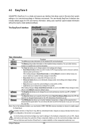
The Memory tab provides information on the installed CPU and motherboard. Grayed-out area(s) indicates that allows users to fine-tune their system-related information without the need to monitor hardware temperature, voltage and fan speed and set . 4-3 EasyTune 6 GIGABYTE's EasyTune 6 is not supported. The Tuner tab allows you to change the core clock...
The Memory tab provides information on the installed CPU and motherboard. Grayed-out area(s) indicates that allows users to fine-tune their system-related information without the need to monitor hardware temperature, voltage and fan speed and set . 4-3 EasyTune 6 GIGABYTE's EasyTune 6 is not supported. The Tuner tab allows you to change the core clock...

Manual
Page 70
...and power savings meter is restarted. Total Mode In Total Mode, users are set to Enabled. (Note 2) 1: Smart FAN/CPU (default); 2: Smart FAN/CPU/VGA/HDD; 3: Smart FAN/CPU/VGA/HDD/Chipset/ Memory. (Note 3) The total amount of power saved will continue to see how much total power...4 65 1 7 8 14 10 15 9 Total Mode - Button Information Table Button Description 1 Dynamic Energy Saver On/Off Switch (Default: Off) 2 Current CPU Power Consumption 3 Total Power Savings (Total power saving with the user-defined power saving settings, even after the system is unable to reset to zero...
...and power savings meter is restarted. Total Mode In Total Mode, users are set to Enabled. (Note 2) 1: Smart FAN/CPU (default); 2: Smart FAN/CPU/VGA/HDD; 3: Smart FAN/CPU/VGA/HDD/Chipset/ Memory. (Note 3) The total amount of power saved will continue to see how much total power...4 65 1 7 8 14 10 15 9 Total Mode - Button Information Table Button Description 1 Dynamic Energy Saver On/Off Switch (Default: Off) 2 Current CPU Power Consumption 3 Total Power Savings (Total power saving with the user-defined power saving settings, even after the system is unable to reset to zero...


