Manual
Page 1
GA-H55M-D2H LGA1156 socket motherboard for Intel® Core™ i7 processor family/ Intel® Core™ i5 processor family/ Intel® Core™ i3 processor family User's Manual Rev. 1301 12ME-H55MD2H-1301R
GA-H55M-D2H LGA1156 socket motherboard for Intel® Core™ i7 processor family/ Intel® Core™ i5 processor family/ Intel® Core™ i3 processor family User's Manual Rev. 1301 12ME-H55MD2H-1301R
Manual
Page 2
Motherboard GA-H55M-D2H May 17, 2010 Motherboard GA-H55M-D2H May 17, 2010
Motherboard GA-H55M-D2H May 17, 2010 Motherboard GA-H55M-D2H May 17, 2010
Manual
Page 3
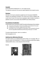
... are legally registered to use of this : "REV: X.X." Check your motherboard looks like this product, GIGABYTE provides the following types of documentations: For quick set-up of the motherboard is protected by GIGABYTE without GIGABYTE's prior written permission. The trademarks mentioned in the use GIGABYTE's unique features, read the Quick Installation Guide included with the product...
... are legally registered to use of this : "REV: X.X." Check your motherboard looks like this product, GIGABYTE provides the following types of documentations: For quick set-up of the motherboard is protected by GIGABYTE without GIGABYTE's prior written permission. The trademarks mentioned in the use GIGABYTE's unique features, read the Quick Installation Guide included with the product...

Manual
Page 4
Table of Contents Box Contents...6 Optional Items...6 GA-H55M-D2H Motherboard Layout 7 GA-H55M-D2H Motherboard Block Diagram 8 Chapter 1 Hardware Installation 9 1-1 Installation Precautions 9 1-2 Product Specifications 10 1-3 Installing the CPU and CPU Cooler 13 1-3-1 Installing the CPU 13 1-3-2 Installing the CPU Cooler ...
Table of Contents Box Contents...6 Optional Items...6 GA-H55M-D2H Motherboard Layout 7 GA-H55M-D2H Motherboard Block Diagram 8 Chapter 1 Hardware Installation 9 1-1 Installation Precautions 9 1-2 Product Specifications 10 1-3 Installing the CPU and CPU Cooler 13 1-3-1 Installing the CPU 13 1-3-2 Installing the CPU Cooler ...
Manual
Page 6
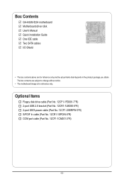
Box Contents GA-H55M-D2H motherboard Motherboard driver disk User's Manual Quick Installation Guide One IDE cable Two SATA cables I/O Shield • The box contents above are subject to change without notice. • The motherboard image is for reference only and the actual items shall depend on the product package you obtain. Optional Items Floppy disk drive...
Box Contents GA-H55M-D2H motherboard Motherboard driver disk User's Manual Quick Installation Guide One IDE cable Two SATA cables I/O Shield • The box contents above are subject to change without notice. • The motherboard image is for reference only and the actual items shall depend on the product package you obtain. Optional Items Floppy disk drive...
Manual
Page 7
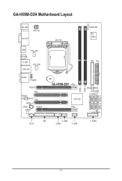
GA-H55M-D2H Motherboard Layout KB_USB ATX_12V VGA_DVI LGA1156 PHASE LED iTE IT8720 HDMI SYS_FAN OPTICAL R_USB USB_LAN CPU_FAN AUDIO F_AUDIO PCIEX16 PCI1 Realtek RTL8111D/8111E PCI2 SPDIF_O SPDIF_I CODEC PCIEX4 IDE ATX BAT GA-H55M-D2H Intel® H55 JMicron JMB368 M_BIOS B_BIOS CLR_CMOS FDD CD_IN F_USB2 COMA F_USB1 F_PANEL DDR3_1 DDR3_2 SATA2_5 SATA2_2 SATA2_4 SATA2_1 SATA2_3 SATA2_0 - 7 -
GA-H55M-D2H Motherboard Layout KB_USB ATX_12V VGA_DVI LGA1156 PHASE LED iTE IT8720 HDMI SYS_FAN OPTICAL R_USB USB_LAN CPU_FAN AUDIO F_AUDIO PCIEX16 PCI1 Realtek RTL8111D/8111E PCI2 SPDIF_O SPDIF_I CODEC PCIEX4 IDE ATX BAT GA-H55M-D2H Intel® H55 JMicron JMB368 M_BIOS B_BIOS CLR_CMOS FDD CD_IN F_USB2 COMA F_USB1 F_PANEL DDR3_1 DDR3_2 SATA2_5 SATA2_2 SATA2_4 SATA2_1 SATA2_3 SATA2_0 - 7 -
Manual
Page 8
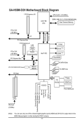
GA-H55M-D2H Motherboard Block Diagram 1 PCI Express x16 CPU CLK+/- (133 MHz) LGA1156 CPU DDR3 1666 (O.C.)/1333/1066/800 MHz Dual Channel Memory PCIe CLK (100 MHz) x16 ...
GA-H55M-D2H Motherboard Block Diagram 1 PCI Express x16 CPU CLK+/- (133 MHz) LGA1156 CPU DDR3 1666 (O.C.)/1333/1066/800 MHz Dual Channel Memory PCIe CLK (100 MHz) x16 ...

Manual
Page 9
... turning on the computer power during the installation process can become damaged as a motherboard, CPU or memory. Hardware Installation Chapter 1 Hardware Installation 1-1 Installation Precautions The motherboard contains numerous delicate electronic circuits and components which can lead to damage to system ... ESD wrist strap, keep your hands dry and first touch a metal object to eliminate static electricity. • Prior to installing the motherboard, please have a problem related to the use of the product, please consult a certified computer technician. - 9 - These stickers are...
... turning on the computer power during the installation process can become damaged as a motherboard, CPU or memory. Hardware Installation Chapter 1 Hardware Installation 1-1 Installation Precautions The motherboard contains numerous delicate electronic circuits and components which can lead to damage to system ... ESD wrist strap, keep your hands dry and first touch a metal object to eliminate static electricity. • Prior to installing the motherboard, please have a problem related to the use of the product, please consult a certified computer technician. - 9 - These stickers are...
Manual
Page 12
... CPU/system fan speed control function is supported will depend on the CPU/system cooler you install. (Note 8) Available functions in EasyTune may differ by motherboard model. Hardware Installation - 12 -
... CPU/system fan speed control function is supported will depend on the CPU/system cooler you install. (Note 8) Available functions in EasyTune may differ by motherboard model. Hardware Installation - 12 -
Manual
Page 13
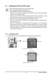
...incorrectly. (Or you may occur. • Set the CPU host frequency in accordance with the CPU specifications. Locate the alignment keys on the motherboard CPU socket and the notches on the CPU - 13 - Hardware Installation LGA1156 CPU Socket Alignment Key Alignment Key Pin One Corner of the ...• Apply an even and thin layer of thermal grease on the computer if the CPU cooler is not recommended that the motherboard supports the CPU. (Go to GIGABYTE's website for the peripherals. age of the CPU Socket LGA1156 CPU Notch Notch Triangle Pin One Marking on the CPU. 1-3 ...
...incorrectly. (Or you may occur. • Set the CPU host frequency in accordance with the CPU specifications. Locate the alignment keys on the motherboard CPU socket and the notches on the CPU - 13 - Hardware Installation LGA1156 CPU Socket Alignment Key Alignment Key Pin One Corner of the ...• Apply an even and thin layer of thermal grease on the computer if the CPU cooler is not recommended that the motherboard supports the CPU. (Go to GIGABYTE's website for the peripherals. age of the CPU Socket LGA1156 CPU Notch Notch Triangle Pin One Marking on the CPU. 1-3 ...

Manual
Page 14
... 2: Remove the CPU socket cover as well. Step 4: Once the CPU is under the shoulder screw. Step 5: Push the CPU socket lever back into the motherboard CPU socket. Before installing the CPU, make sure the front end of the load plate is properly inserted, use one corner of the socket cover...
... 2: Remove the CPU socket cover as well. Step 4: Once the CPU is under the shoulder screw. Step 5: Push the CPU socket lever back into the motherboard CPU socket. Before installing the CPU, make sure the front end of the load plate is properly inserted, use one corner of the socket cover...

Manual
Page 15
... on the push pins diagonally. Check that the Male and Female push pins are joined closely. (Refer to the CPU fan header (CPU_FAN) on the motherboard. Inadequately removing the CPU cooler may adhere to remove the cooler, on the contrary, is complete. Step 2: Before installing the cooler, note the direction of... Cooler Follow the steps below to install.) Step 3: Place the cooler atop the CPU, aligning the four push pins through the pin holes on the motherboard. If the push pin is inserted as the picture above shows, the installation is to correctly install the CPU cooler on the...
... on the push pins diagonally. Check that the Male and Female push pins are joined closely. (Refer to the CPU fan header (CPU_FAN) on the motherboard. Inadequately removing the CPU cooler may adhere to remove the cooler, on the contrary, is complete. Step 2: Before installing the cooler, note the direction of... Cooler Follow the steps below to install.) Step 3: Place the cooler atop the CPU, aligning the four push pins through the pin holes on the motherboard. If the push pin is inserted as the picture above shows, the installation is to correctly install the CPU cooler on the...
Manual
Page 16
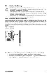
...as following: Channel 0: DDR3_1 Channel 1: DDR3_2 DDR3_1 DDR3_2 Due to CPU limitations, read the following guidelines before you are unable to GIGABYTE's website for optimum performance. Hardware Installation - 16 - After the memory is installed. 2. When enabling Dual Channel mode with two... only one DDR3 memory module is installed, the BIOS will double the original memory bandwidth. Dual Channel Memory Configuration This motherboard provides two DDR3 memory sockets and supports Dual Channel Technology. 1-4 Installing the Memory 1-4-1 Read the following guidelines before installing...
...as following: Channel 0: DDR3_1 Channel 1: DDR3_2 DDR3_1 DDR3_2 Due to CPU limitations, read the following guidelines before you are unable to GIGABYTE's website for optimum performance. Hardware Installation - 16 - After the memory is installed. 2. When enabling Dual Channel mode with two... only one DDR3 memory module is installed, the BIOS will double the original memory bandwidth. Dual Channel Memory Configuration This motherboard provides two DDR3 memory sockets and supports Dual Channel Technology. 1-4 Installing the Memory 1-4-1 Read the following guidelines before installing...

Manual
Page 17
... into the memory socket. DDR3 and DDR2 DIMMs are not compatible to each other or DDR DIMMs. Be sure to install DDR3 DIMMs on this motherboard.
... into the memory socket. DDR3 and DDR2 DIMMs are not compatible to each other or DDR DIMMs. Be sure to install DDR3 DIMMs on this motherboard.
Manual
Page 18
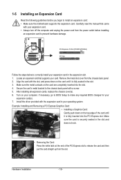
... provided with your computer. Remove the metal slot cover from the power outlet before you begin to install an expansion card: • Make sure the motherboard supports the expansion card. Locate an expansion slot that came with the expansion card in the slot and does not rock. • Removing the Card...
... provided with your computer. Remove the metal slot cover from the power outlet before you begin to install an expansion card: • Make sure the motherboard supports the expansion card. Locate an expansion slot that came with the expansion card in the slot and does not rock. • Removing the Card...
Manual
Page 20
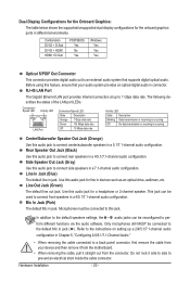
... Yes Optical S/PDIF Out Connector This connector provides digital audio out to an external audio system that your device and then remove it from the motherboard. • When removing the cable, pull it side to side to prevent an electrical short inside the cable connector. The following describes the states of...
... Yes Optical S/PDIF Out Connector This connector provides digital audio out to an external audio system that your device and then remove it from the motherboard. • When removing the cable, pull it side to side to prevent an electrical short inside the cable connector. The following describes the states of...

Manual
Page 21
..., make sure your devices are compliant with the connectors you wish to connect. • Before installing the devices, be sure to the connector on the motherboard. - 21 - Hardware Installation Unplug the power cord from the power outlet to prevent damage to the devices. • After installing the device and before connecting...
..., make sure your devices are compliant with the connectors you wish to connect. • Before installing the devices, be sure to the connector on the motherboard. - 21 - Hardware Installation Unplug the power cord from the power outlet to prevent damage to the devices. • After installing the device and before connecting...

Manual
Page 22
...-pin ATX) Hardware Installation - 22 - The power connector possesses a foolproof design. If the 12V power connector is turned off and all the components on the motherboard. To meet expansion requirements, it is used that can lead to the power connector in the correct orientation. If a power supply is recommended that a power...
...-pin ATX) Hardware Installation - 22 - The power connector possesses a foolproof design. If the 12V power connector is turned off and all the components on the motherboard. To meet expansion requirements, it is used that can lead to the power connector in the correct orientation. If a power supply is recommended that a power...
Manual
Page 23
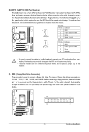
..., 1.44 MB, and 2.88 MB. The pin 1 of floppy disk drives supported are not configuration jumper blocks. Most fan headers possess a foolproof insertion design. The motherboard supports CPU fan speed control, which requires the use of the connector and the floppy disk drive cable. Definition 1 GND 2 +12V / Speed Control 3 Sense 4 ... dealer. 33 1 34 2 - 23 - Before connecting a floppy disk drive, be sure to prevent your CPU and system from overheating. 3/4) CPU_FAN/SYS_FAN (Fan Headers) The motherboard has a 4-pin CPU fan header (CPU_FAN) and a 4-pin system fan header (SYS_FAN).
..., 1.44 MB, and 2.88 MB. The pin 1 of floppy disk drives supported are not configuration jumper blocks. Most fan headers possess a foolproof insertion design. The motherboard supports CPU fan speed control, which requires the use of the connector and the floppy disk drive cable. Definition 1 GND 2 +12V / Speed Control 3 Sense 4 ... dealer. 33 1 34 2 - 23 - Before connecting a floppy disk drive, be sure to prevent your CPU and system from overheating. 3/4) CPU_FAN/SYS_FAN (Fan Headers) The motherboard has a 4-pin CPU fan header (CPU_FAN) and a 4-pin system fan header (SYS_FAN).
Manual
Page 27
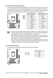
.... 11) CD_IN (CD In Connector) You may connect your chassis front panel audio module to this header. Incorrect connection between the module connector and the motherboard header will be present on each wire instead of a single plug. If your optical drive to work or even damage it. Definition 1 CD-L 1 2 GND 3 ... front panel audio header supports HD audio by default. Pin No. You may connect the audio cable that has separated connectors on both of the motherboard header. For HD Front Panel Audio: For AC'97 Front Panel Audio: Pin No. If you want to mute the back panel audio (only ...
.... 11) CD_IN (CD In Connector) You may connect your chassis front panel audio module to this header. Incorrect connection between the module connector and the motherboard header will be present on each wire instead of a single plug. If your optical drive to work or even damage it. Definition 1 CD-L 1 2 GND 3 ... front panel audio header supports HD audio by default. Pin No. You may connect the audio cable that has separated connectors on both of the motherboard header. For HD Front Panel Audio: For AC'97 Front Panel Audio: Pin No. If you want to mute the back panel audio (only ...


