Manual
Page 1
GA-945P-DS3/S3 Intel® CoreTM 2 Extreme dual-core / CoreTM 2 Duo / Intel® Pentium® D / Pentium® 4 / Celeron® D LGA775 Processor Motherboard User's Manual Rev. 3301 12ME-945PDS3-3301R * The WEEE marking on the product indicates this product must not be disposed of with user's other household waste and must be handed over to a designated collection point for the recycling of waste electrical and electronic equipment!! * The WEEE marking applies only in European Union's member states.
GA-945P-DS3/S3 Intel® CoreTM 2 Extreme dual-core / CoreTM 2 Duo / Intel® Pentium® D / Pentium® 4 / Celeron® D LGA775 Processor Motherboard User's Manual Rev. 3301 12ME-945PDS3-3301R * The WEEE marking on the product indicates this product must not be disposed of with user's other household waste and must be handed over to a designated collection point for the recycling of waste electrical and electronic equipment!! * The WEEE marking applies only in European Union's member states.
Manual
Page 2
Motherboard GA-945P-DS3/GA-945P-S3 Oct. 27, 2006 Motherboard GA-945P-DS3/ GA-945P-S3 Oct. 27, 2006
Motherboard GA-945P-DS3/GA-945P-S3 Oct. 27, 2006 Motherboard GA-945P-DS3/ GA-945P-S3 Oct. 27, 2006
Manual
Page 4
... Status 42 2-7 MB Intelligent Tweaker(M.I /O Back Panel Introduction 17 1-7 Connectors Introduction 18 Chapter 2 BIOS Setup 29 The Main Menu (For example: GA-945P-DS3 BIOS Ver. Table of Contents ItemChecklist ...6 OptionalAccessories ...6 GA-945P-DS3/GA-945P-S3 Motherboard Layout 7 Block Diagram ...8 Chapter 1 Hardware Installation 9 1-1 Considerations Prior to Installation 9 1-2 Feature Summary 10 1-3 Installation of the CPU and CPU Cooler 12...
... Status 42 2-7 MB Intelligent Tweaker(M.I /O Back Panel Introduction 17 1-7 Connectors Introduction 18 Chapter 2 BIOS Setup 29 The Main Menu (For example: GA-945P-DS3 BIOS Ver. Table of Contents ItemChecklist ...6 OptionalAccessories ...6 GA-945P-DS3/GA-945P-S3 Motherboard Layout 7 Block Diagram ...8 Chapter 1 Hardware Installation 9 1-1 Considerations Prior to Installation 9 1-2 Feature Summary 10 1-3 Installation of the CPU and CPU Cooler 12...
Manual
Page 7
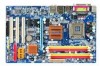
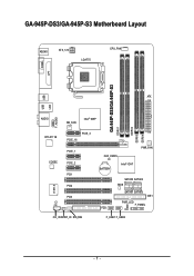
GA-945P-DS3/GA-945P-S3 Motherboard Layout KB_MS ATX_12V LGA775 CPU_FAN COMA LPT GA-945P-DS3/GA-945P-S3 DDRII1 DDRII2 DDRII3 DDRII4 USB USB LAN ATX F_AUDIO AUDIO NB_FAN Intel® 945P RTL8111B CODEC CI IT8718 PCIE_16 PCIE_3 PCIE_1 PCIE_2 PCI1 PCI2 PCI3 CD_IN SPDIF_IO SYS_FAN CLR_CMOS BATTERY Intel® ICH7 PWR_FAN SATAII0 SATAII2 BIOS SATAII1 SATAII3 IDE1 PWR_LED F_PANEL FDD F_USB1 F_USB2 - 7 -
GA-945P-DS3/GA-945P-S3 Motherboard Layout KB_MS ATX_12V LGA775 CPU_FAN COMA LPT GA-945P-DS3/GA-945P-S3 DDRII1 DDRII2 DDRII3 DDRII4 USB USB LAN ATX F_AUDIO AUDIO NB_FAN Intel® 945P RTL8111B CODEC CI IT8718 PCIE_16 PCIE_3 PCIE_1 PCIE_2 PCI1 PCI2 PCI3 CD_IN SPDIF_IO SYS_FAN CLR_CMOS BATTERY Intel® ICH7 PWR_FAN SATAII0 SATAII2 BIOS SATAII1 SATAII3 IDE1 PWR_LED F_PANEL FDD F_USB1 F_USB2 - 7 -
Manual
Page 8
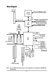
...) LGA775 Processor CPU CLK+/-(266/200/133 MHz) PCI Express x16 LAN RJ45 RTL8111B Host Interface DDRII 667(Note)/533/400 MHz DIMM Intel® 945P Dual Channel Memory MCH CLK (266/200/133 MHz) PCI Express Bus x1 x1 x1 x1 PCIe CLK Intel® (100 MHz) ICH7 3 PCI Express... MIC Line-Out Line-In SPDIF In SPDIF Out 3 PCI PCI CLK (33 MHz) 8 USB Ports (Note) To use a DDRII 667 memory module on the motherboard, you must install a 1066/800 MHz FSB processor. - 8 -
...) LGA775 Processor CPU CLK+/-(266/200/133 MHz) PCI Express x16 LAN RJ45 RTL8111B Host Interface DDRII 667(Note)/533/400 MHz DIMM Intel® 945P Dual Channel Memory MCH CLK (266/200/133 MHz) PCI Express Bus x1 x1 x1 x1 PCIe CLK Intel® (100 MHz) ICH7 3 PCI Express... MIC Line-Out Line-In SPDIF In SPDIF Out 3 PCI PCI CLK (33 MHz) 8 USB Ports (Note) To use a DDRII 667 memory module on the motherboard, you must install a 1066/800 MHz FSB processor. - 8 -
Manual
Page 9
...for warranty validation. 2. Please verify that all cables and power connectors are no leftover screws or metal components placed on the motherboard or within a electrostatic shielding container. 5. Damage due to wear an electrostatic discharge (ESD) cuff when handling electronic components (...human cause. 2. Turning on an uneven surface. 7. Damage due to be an unofficial Gigabyte product. - 9 - Thus, prior to Installation Preparing Your Computer The motherboard contains numerous delicate electronic circuits and components which can lead to damage to system components as ...
...for warranty validation. 2. Please verify that all cables and power connectors are no leftover screws or metal components placed on the motherboard or within a electrostatic shielding container. 5. Damage due to wear an electrostatic discharge (ESD) cuff when handling electronic components (...human cause. 2. Turning on an uneven surface. 7. Damage due to be an unofficial Gigabyte product. - 9 - Thus, prior to Installation Preparing Your Computer The motherboard contains numerous delicate electronic circuits and components which can lead to damage to system components as ...
Manual
Page 10
GA-945P-DS3/S3 Motherboard - 10 - English 1-2 Feature Summary CPU Š LGA775 for Intel® CoreTM 2 Extreme dual-core/CoreTM 2 Duo/Pentium® D/ Pentium® 4/Celeron® D Š L2 cache varies with CPU Front Side Bus Š Supports 1066/800/533 MHz FSB Chipset Š Northbridge: Intel® 945P Express Chipset Š Southbridge: Intel&#...Š 1 S/PDIF In/Out connector Š 2 USB 2.0/1.1 connectors for additional 4 ports by cables Š 1 power LED connector Š 1 Chassis Intrusion connector "*" Only the GA-945P-DS3 adopts All-Solid Capacitor design.
GA-945P-DS3/S3 Motherboard - 10 - English 1-2 Feature Summary CPU Š LGA775 for Intel® CoreTM 2 Extreme dual-core/CoreTM 2 Duo/Pentium® D/ Pentium® 4/Celeron® D Š L2 cache varies with CPU Front Side Bus Š Supports 1066/800/533 MHz FSB Chipset Š Northbridge: Intel® 945P Express Chipset Š Southbridge: Intel&#...Š 1 S/PDIF In/Out connector Š 2 USB 2.0/1.1 connectors for additional 4 ports by cables Š 1 power LED connector Š 1 Chassis Intrusion connector "*" Only the GA-945P-DS3 adopts All-Solid Capacitor design.
Manual
Page 11
..., a certain amount of memory size will instead be shown as 3.xx GB memory during system startup. (Note 2) To use a DDRII 667 memory module on the motherboard, you must install a 1066/800 MHz FSB processor. (Note 3) EasyTune functions may vary depending on different...
..., a certain amount of memory size will instead be shown as 3.xx GB memory during system startup. (Note 2) To use a DDRII 667 memory module on the motherboard, you must install a 1066/800 MHz FSB processor. (Note 3) EasyTune functions may vary depending on different...
Manual
Page 12
Please set the CPU host frequency in accordance with the following platform components: - BIOS: A BIOS that the motherboard supports the CPU. 2. Fig. 2 Remove the plastic covering on the edge of heat paste between your thumb and forefinger, carefully place...bending motions that supports HT Technology - If you wish to set beyond the proper specifications, please do so according to the CPU during installation.) GA-945P-DS3/S3 Motherboard - 12 - Please add an even layer of the CPU socket. HT functionality requirement content : Enabling the functionality of the CPU may occur....
Please set the CPU host frequency in accordance with the following platform components: - BIOS: A BIOS that the motherboard supports the CPU. 2. Fig. 2 Remove the plastic covering on the edge of heat paste between your thumb and forefinger, carefully place...bending motions that supports HT Technology - If you wish to set beyond the proper specifications, please do so according to the CPU during installation.) GA-945P-DS3/S3 Motherboard - 12 - Please add an even layer of the CPU socket. HT functionality requirement content : Enabling the functionality of the CPU may occur....
Manual
Page 13
... CPU Cooler Male Push Pin The top of Female Push Pin Female Push Pin Fig.1 Please apply an even layer of heat paste on the motherboard. The CPU cooler may adhere to the pin hole on the male push pin doesn't face inwards before installation. (This instruction is only for Intel... prevent such an occurrence, it is to install.) Please note the direction of the installed CPU. Fig. 2 (Turning the push pin along the direction of motherboard after installing. Fig. 4 Please make sure the push pins aim to the CPU as the picture, the installation is complete. Fig. 6 Finally, please attach the...
... CPU Cooler Male Push Pin The top of Female Push Pin Female Push Pin Fig.1 Please apply an even layer of heat paste on the motherboard. The CPU cooler may adhere to the pin hole on the male push pin doesn't face inwards before installation. (This instruction is only for Intel... prevent such an occurrence, it is to install.) Please note the direction of the installed CPU. Fig. 2 (Turning the push pin along the direction of motherboard after installing. Fig. 4 Please make sure the push pins aim to the CPU as the picture, the installation is complete. Fig. 6 Finally, please attach the...
Manual
Page 14
...direction. Notch DDRII Fig.1 The DIMM socket has a notch, so the DIMM memory module can be used is supported by the motherboard. Please make sure that the computer power is recommended that memory of the DIMM sockets to insert the module, please switch the ...down. It is switched off to remove the DIMM module. Insert the DIMM memory module vertically into the DIMM socket. GA-945P-DS3/S3 Motherboard - 14 - The motherboard supports DDRII memory modules, whereby BIOS will automatically detect memory capacity and specifications. Reverse the installation steps when you are designed...
...direction. Notch DDRII Fig.1 The DIMM socket has a notch, so the DIMM memory module can be used is supported by the motherboard. Please make sure that the computer power is recommended that memory of the DIMM sockets to insert the module, please switch the ...down. It is switched off to remove the DIMM module. Insert the DIMM memory module vertically into the DIMM socket. GA-945P-DS3/S3 Motherboard - 14 - The motherboard supports DDRII memory modules, whereby BIOS will automatically detect memory capacity and specifications. Reverse the installation steps when you are designed...
Manual
Page 16
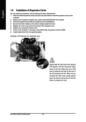
English 1-5 Installation of the expansion card. 6. Be sure the metal contacts on the slot. Install related driver from BIOS. 8. GA-945P-DS3/S3 Motherboard - 16 - Replace the screw to secure the slot bracket of Expansion Cards You can install your VGA card is locked by following the steps outlined ... as the picture to the left shows to the onboard PCI Express x16 slot and press firmly down on the card are indeed seated in motherboard. 4. Remove your computer's chassis cover. 7. Installing a PCI Express x16 expansion card: Please align the VGA card to release the card...
English 1-5 Installation of the expansion card. 6. Be sure the metal contacts on the slot. Install related driver from BIOS. 8. GA-945P-DS3/S3 Motherboard - 16 - Replace the screw to secure the slot bracket of Expansion Cards You can install your VGA card is locked by following the steps outlined ... as the picture to the left shows to the onboard PCI Express x16 slot and press firmly down on the card are indeed seated in motherboard. 4. Remove your computer's chassis cover. 7. Installing a PCI Express x16 expansion card: Please align the VGA card to release the card...
Manual
Page 18
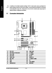
... 8) IDE1 9) SATAII0/1/2/3 7 15 10 11 10) PWR_LED 11) F_PANEL 12) F_AUDIO 13) CD_IN 14) SPDIF_IO 15) F_USB1/F_USB2 16) CI 17) CLR_CMOS 18) BATTERY GA-945P-DS3/S3 Motherboard - 18 - Only microphones still MUST be reconfigured to perform different functions via the audio software. English In addition to the default speakers settings, the ~ audio...
... 8) IDE1 9) SATAII0/1/2/3 7 15 10 11 10) PWR_LED 11) F_PANEL 12) F_AUDIO 13) CD_IN 14) SPDIF_IO 15) F_USB1/F_USB2 16) CI 17) CLR_CMOS 18) BATTERY GA-945P-DS3/S3 Motherboard - 18 - Only microphones still MUST be reconfigured to perform different functions via the audio software. English In addition to the default speakers settings, the ~ audio...
Manual
Page 19
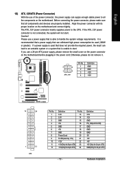
... 24-pin ATX) - 19 - If you use a 24-pin ATX power supply, please remove the small cover on the power connector on the motherboard and connect tightly. English 1/2) ATX_12V/ATX (Power Connector) With the use of the power connector, the power supply can supply enough stable power to... to start . Hardware Installation Before connecting the power connector, please make sure that all the components on the motherboard. Align the power connector with its proper location on the motherboard before plugging in the power cord; It is recommended that a power supply that can lead to an unstable ...
... 24-pin ATX) - 19 - If you use a 24-pin ATX power supply, please remove the small cover on the power connector on the motherboard and connect tightly. English 1/2) ATX_12V/ATX (Power Connector) With the use of the power connector, the power supply can supply enough stable power to... to start . Hardware Installation Before connecting the power connector, please make sure that all the components on the motherboard. Align the power connector with its proper location on the motherboard before plugging in the power cord; It is recommended that a power supply that can lead to an unstable ...
Manual
Page 20
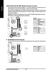
... power voltage. Most coolers are designed with color-coded power connector wires. The black connector wire is the ground wire (GND). Definition 1 GND 1 2 +12V 3 NC GA-945P-DS3/S3 Motherboard - 20 - English 3/4/5) CPU_FAN / SYS_FAN / PWR_FAN (Cooler Fan Power Connector) The cooler fan power connector supplies a +12V power voltage via a 3-pin/4-pin (only for CPU_FAN...
... power voltage. Most coolers are designed with color-coded power connector wires. The black connector wire is the ground wire (GND). Definition 1 GND 1 2 +12V 3 NC GA-945P-DS3/S3 Motherboard - 20 - English 3/4/5) CPU_FAN / SYS_FAN / PWR_FAN (Cooler Fan Power Connector) The cooler fan power connector supplies a +12V power voltage via a 3-pin/4-pin (only for CPU_FAN...
Manual
Page 22
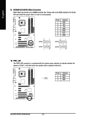
Definition 1 MPD+ 1 2 MPD- 3 MPD- It will blink when the system enters suspend mode (S1). GA-945P-DS3/S3 Motherboard - 22 - Please refer to the BIOS setting for the Serial ATA and install the proper driver in order to work properly. 7 1 SATAII0 Pin No. 1 2 3 4 5 6 7 Definition ...
Definition 1 MPD+ 1 2 MPD- 3 MPD- It will blink when the system enters suspend mode (S1). GA-945P-DS3/S3 Motherboard - 22 - Please refer to the BIOS setting for the Serial ATA and install the proper driver in order to work properly. 7 1 SATAII0 Pin No. 1 2 3 4 5 6 7 Definition ...
Manual
Page 24
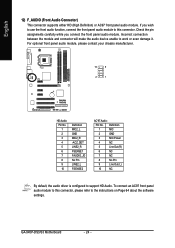
... panel audio module. Incorrect connection between the module and connector will make the audio device unable to this connector, please refer to support HD Audio. GA-945P-DS3/S3 Motherboard - 24 - English 12) F_AUDIO (Front Audio Connector) This connector supports either HD (High Definition) or AC97 front panel audio module.
... panel audio module. Incorrect connection between the module and connector will make the audio device unable to this connector, please refer to support HD Audio. GA-945P-DS3/S3 Motherboard - 24 - English 12) F_AUDIO (Front Audio Connector) This connector supports either HD (High Definition) or AC97 front panel audio module.
Manual
Page 26
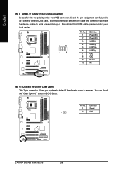
... NC 16) CI (Chassis Intrusion, Case Open) This 2-pin connector allows your system to work or even damage it. Pin No. Definition 1 Signal 1 2 GND GA-945P-DS3/S3 Motherboard - 26 - English 15) F_ USB1 / F_USB2 (Front USB Connector) Be careful with the polarity of the front USB connector. Check the pin assignment carefully while...
... NC 16) CI (Chassis Intrusion, Case Open) This 2-pin connector allows your system to work or even damage it. Pin No. Definition 1 Signal 1 2 GND GA-945P-DS3/S3 Motherboard - 26 - English 15) F_ USB1 / F_USB2 (Front USB Connector) Be careful with the polarity of the front USB connector. Check the pin assignment carefully while...
Manual
Page 28
English GA-945P-DS3/S3 Motherboard - 28 -
English GA-945P-DS3/S3 Motherboard - 28 -
Manual
Page 29
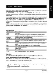
... Menu and Option Page Setup Menu - To exit the Help Window press . When the power is turned off, the battery on the motherboard supplies the necessary power to DOS before upgrading BIOS but directly download and update BIOS from BIOS default table Load the Optimized Defaults Q-Flash ... Menu The on-line description of the highlighted setup function is displayed at the bottom of the motherboard. The CMOS SETUP saves the configuration in system malfunction. - 29 - If you to a new BIOS, either Gigabyte's Q-Flash or @BIOS utility can enter the BIOS setup screen by pressing "Ctrl + F1"....
... Menu and Option Page Setup Menu - To exit the Help Window press . When the power is turned off, the battery on the motherboard supplies the necessary power to DOS before upgrading BIOS but directly download and update BIOS from BIOS default table Load the Optimized Defaults Q-Flash ... Menu The on-line description of the highlighted setup function is displayed at the bottom of the motherboard. The CMOS SETUP saves the configuration in system malfunction. - 29 - If you to a new BIOS, either Gigabyte's Q-Flash or @BIOS utility can enter the BIOS setup screen by pressing "Ctrl + F1"....


