Manual
Page 1
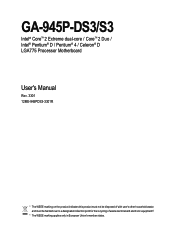
GA-945P-DS3/S3 Intel® CoreTM 2 Extreme dual-core / CoreTM 2 Duo / Intel® Pentium® D / Pentium® 4 / Celeron® D LGA775 Processor Motherboard User's Manual Rev. 3301 12ME-945PDS3-3301R * The WEEE marking on the product indicates this product must not be disposed of with user's other household waste and must be handed over to a designated collection point for the recycling of waste electrical and electronic equipment!! * The WEEE marking applies only in European Union's member states.
GA-945P-DS3/S3 Intel® CoreTM 2 Extreme dual-core / CoreTM 2 Duo / Intel® Pentium® D / Pentium® 4 / Celeron® D LGA775 Processor Motherboard User's Manual Rev. 3301 12ME-945PDS3-3301R * The WEEE marking on the product indicates this product must not be disposed of with user's other household waste and must be handed over to a designated collection point for the recycling of waste electrical and electronic equipment!! * The WEEE marking applies only in European Union's member states.
Manual
Page 2
Motherboard GA-945P-DS3/GA-945P-S3 Oct. 27, 2006 Motherboard GA-945P-DS3/ GA-945P-S3 Oct. 27, 2006
Motherboard GA-945P-DS3/GA-945P-S3 Oct. 27, 2006 Motherboard GA-945P-DS3/ GA-945P-S3 Oct. 27, 2006
Manual
Page 4
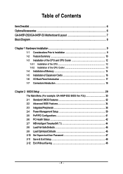
Table of Contents ItemChecklist ...6 OptionalAccessories ...6 GA-945P-DS3/GA-945P-S3 Motherboard Layout 7 Block Diagram ...8 Chapter 1 Hardware Installation 9 1-1 Considerations Prior to Installation 9 1-2 Feature Summary 10 1-3 Installation of the CPU and CPU Cooler 12 1-3-1 Installation of the ... Configurations 41 2-6 PC Health Status 42 2-7 MB Intelligent Tweaker(M.I /O Back Panel Introduction 17 1-7 Connectors Introduction 18 Chapter 2 BIOS Setup 29 The Main Menu (For example: GA-945P-DS3 BIOS Ver.
Table of Contents ItemChecklist ...6 OptionalAccessories ...6 GA-945P-DS3/GA-945P-S3 Motherboard Layout 7 Block Diagram ...8 Chapter 1 Hardware Installation 9 1-1 Considerations Prior to Installation 9 1-2 Feature Summary 10 1-3 Installation of the CPU and CPU Cooler 12 1-3-1 Installation of the ... Configurations 41 2-6 PC Health Status 42 2-7 MB Intelligent Tweaker(M.I /O Back Panel Introduction 17 1-7 Connectors Introduction 18 Chapter 2 BIOS Setup 29 The Main Menu (For example: GA-945P-DS3 BIOS Ver.
Manual
Page 7
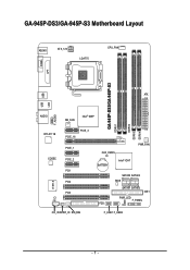
GA-945P-DS3/GA-945P-S3 Motherboard Layout KB_MS ATX_12V LGA775 CPU_FAN COMA LPT GA-945P-DS3/GA-945P-S3 DDRII1 DDRII2 DDRII3 DDRII4 USB USB LAN ATX F_AUDIO AUDIO NB_FAN Intel® 945P RTL8111B CODEC CI IT8718 PCIE_16 PCIE_3 PCIE_1 PCIE_2 PCI1 PCI2 PCI3 CD_IN SPDIF_IO SYS_FAN CLR_CMOS BATTERY Intel® ICH7 PWR_FAN SATAII0 SATAII2 BIOS SATAII1 SATAII3 IDE1 PWR_LED F_PANEL FDD F_USB1 F_USB2 - 7 -
GA-945P-DS3/GA-945P-S3 Motherboard Layout KB_MS ATX_12V LGA775 CPU_FAN COMA LPT GA-945P-DS3/GA-945P-S3 DDRII1 DDRII2 DDRII3 DDRII4 USB USB LAN ATX F_AUDIO AUDIO NB_FAN Intel® 945P RTL8111B CODEC CI IT8718 PCIE_16 PCIE_3 PCIE_1 PCIE_2 PCI1 PCI2 PCI3 CD_IN SPDIF_IO SYS_FAN CLR_CMOS BATTERY Intel® ICH7 PWR_FAN SATAII0 SATAII2 BIOS SATAII1 SATAII3 IDE1 PWR_LED F_PANEL FDD F_USB1 F_USB2 - 7 -
Manual
Page 10
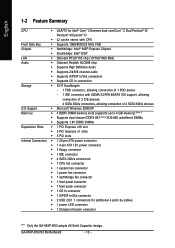
...® 4/Celeron® D Š L2 cache varies with CPU Front Side Bus Š Supports 1066/800/533 MHz FSB Chipset Š Northbridge: Intel® 945P Express Chipset Š Southbridge: Intel® ICH7 LAN Š Onboard RTL8111B chip (10/100/1000 Mbit) Audio Š Onboard Realtek ALC888 chip Š Supports High... Š 1 S/PDIF In/Out connector Š 2 USB 2.0/1.1 connectors for additional 4 ports by cables Š 1 power LED connector Š 1 Chassis Intrusion connector "*" Only the GA-945P-DS3 adopts All-Solid Capacitor design. GA-945P-DS3/S3 Motherboard - 10 -
...® 4/Celeron® D Š L2 cache varies with CPU Front Side Bus Š Supports 1066/800/533 MHz FSB Chipset Š Northbridge: Intel® 945P Express Chipset Š Southbridge: Intel® ICH7 LAN Š Onboard RTL8111B chip (10/100/1000 Mbit) Audio Š Onboard Realtek ALC888 chip Š Supports High... Š 1 S/PDIF In/Out connector Š 2 USB 2.0/1.1 connectors for additional 4 ports by cables Š 1 power LED connector Š 1 Chassis Intrusion connector "*" Only the GA-945P-DS3 adopts All-Solid Capacitor design. GA-945P-DS3/S3 Motherboard - 10 -
Manual
Page 12
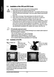
... that might cause damage to the upright position. Fig. 3 Notice the small gold colored triangle located on the CPU socket to the CPU during installation.) GA-945P-DS3/S3 Motherboard - 12 - Avoid twisting or bending motions that supports HT Technology - OS: An operation system that the motherboard supports the CPU. 2. Fig. 2 Remove the plastic...
... that might cause damage to the upright position. Fig. 3 Notice the small gold colored triangle located on the CPU socket to the CPU during installation.) GA-945P-DS3/S3 Motherboard - 12 - Avoid twisting or bending motions that supports HT Technology - OS: An operation system that the motherboard supports the CPU. 2. Fig. 2 Remove the plastic...
Manual
Page 14
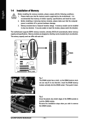
... Fig.1 The DIMM socket has a notch, so the DIMM memory module can be installed in one direction. Memory modules are unable to prevent hardware damage. 3. GA-945P-DS3/S3 Motherboard - 14 - Please make sure that the computer power is recommended that they can only fit in only one direction. Then push it down. If...
... Fig.1 The DIMM socket has a notch, so the DIMM memory module can be installed in one direction. Memory modules are unable to prevent hardware damage. 3. GA-945P-DS3/S3 Motherboard - 14 - Please make sure that the computer power is recommended that they can only fit in only one direction. Then push it down. If...
Manual
Page 15
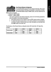
... due to the limitation of the same color. To enable Dual Channel mode with two or four memory modules (it is installed. 2. Hardware Installation The GA-945P-DS3/S3 includes 4 DIMM sockets, and each Channel has two DIMM sockets as following: Channel 0 : DDRII1, DDRII2 Channel 1 : DDRII3, DDRII4 If you want to use memory modules..., chips, and speed), you must install them into DIMM sockets of Intel chipset specifications. 1. Dual Channel mode will double. English Dual Channel Memory Configuration The GA-945P-DS3/S3 supports the Dual Channel Technology.
... due to the limitation of the same color. To enable Dual Channel mode with two or four memory modules (it is installed. 2. Hardware Installation The GA-945P-DS3/S3 includes 4 DIMM sockets, and each Channel has two DIMM sockets as following: Channel 0 : DDRII1, DDRII2 Channel 1 : DDRII3, DDRII4 If you want to use memory modules..., chips, and speed), you must install them into DIMM sockets of Intel chipset specifications. 1. Dual Channel mode will double. English Dual Channel Memory Configuration The GA-945P-DS3/S3 supports the Dual Channel Technology.
Manual
Page 16
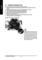
... install the expansion card into expansion slot in the slot. 5. Power on the computer, if necessary, setup BIOS utility of expansion card from the computer. 3. GA-945P-DS3/S3 Motherboard - 16 - When you try uninstall the VGA card, please gently press the latch as the picture to the left shows to secure the slot...
... install the expansion card into expansion slot in the slot. 5. Power on the computer, if necessary, setup BIOS utility of expansion card from the computer. 3. GA-945P-DS3/S3 Motherboard - 16 - When you try uninstall the VGA card, please gently press the latch as the picture to the left shows to secure the slot...
Manual
Page 18
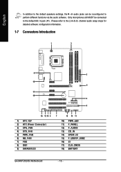
... 7) FDD 8) IDE1 9) SATAII0/1/2/3 7 15 10 11 10) PWR_LED 11) F_PANEL 12) F_AUDIO 13) CD_IN 14) SPDIF_IO 15) F_USB1/F_USB2 16) CI 17) CLR_CMOS 18) BATTERY GA-945P-DS3/S3 Motherboard - 18 - Only microphones still MUST be reconfigured to perform different functions via the audio software. English In addition to the default speakers settings, the...
... 7) FDD 8) IDE1 9) SATAII0/1/2/3 7 15 10 11 10) PWR_LED 11) F_PANEL 12) F_AUDIO 13) CD_IN 14) SPDIF_IO 15) F_USB1/F_USB2 16) CI 17) CLR_CMOS 18) BATTERY GA-945P-DS3/S3 Motherboard - 18 - Only microphones still MUST be reconfigured to perform different functions via the audio software. English In addition to the default speakers settings, the...
Manual
Page 20
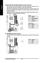
... overheating. 1 CPU_FAN CPU_FAN: Pin No. 1 2 3 4 Definition GND +12V/Speed Control Sense Speed Control 1 SYS_FAN 1 PWR_FAN SYS_FAN/PWR_FAN: Pin No. Pin No. Definition 1 GND 1 2 +12V 3 NC GA-945P-DS3/S3 Motherboard - 20 - The black connector wire is the ground wire (GND). English 3/4/5) CPU_FAN / SYS_FAN / PWR_FAN (Cooler Fan Power Connector) The cooler fan power connector supplies...
... overheating. 1 CPU_FAN CPU_FAN: Pin No. 1 2 3 4 Definition GND +12V/Speed Control Sense Speed Control 1 SYS_FAN 1 PWR_FAN SYS_FAN/PWR_FAN: Pin No. Pin No. Definition 1 GND 1 2 +12V 3 NC GA-945P-DS3/S3 Motherboard - 20 - The black connector wire is the ground wire (GND). English 3/4/5) CPU_FAN / SYS_FAN / PWR_FAN (Cooler Fan Power Connector) The cooler fan power connector supplies...
Manual
Page 22
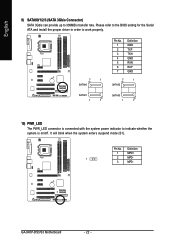
... to work properly. 7 1 SATAII0 Pin No. 1 2 3 4 5 6 7 Definition GND TXP TXN GND RXN RXP GND 7 1 SATAII2 SATAII1 1 7 SATAII3 1 7 10) PWR_LED The PWR_LED connector is on/off. GA-945P-DS3/S3 Motherboard - 22 - Pin No. It will blink when the system enters suspend mode (S1).
... to work properly. 7 1 SATAII0 Pin No. 1 2 3 4 5 6 7 Definition GND TXP TXN GND RXN RXP GND 7 1 SATAII2 SATAII1 1 7 SATAII3 1 7 10) PWR_LED The PWR_LED connector is on/off. GA-945P-DS3/S3 Motherboard - 22 - Pin No. It will blink when the system enters suspend mode (S1).
Manual
Page 24
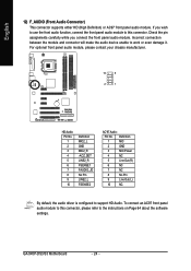
... assignments carefully while you wish to use the front audio function, connect the front panel audio module to this connector, please refer to this connector. GA-945P-DS3/S3 Motherboard - 24 - English 12) F_AUDIO (Front Audio Connector) This connector supports either HD (High Definition) or AC97 front panel audio module. For optional front panel...
... assignments carefully while you wish to use the front audio function, connect the front panel audio module to this connector, please refer to this connector. GA-945P-DS3/S3 Motherboard - 24 - English 12) F_AUDIO (Front Audio Connector) This connector supports either HD (High Definition) or AC97 front panel audio module. For optional front panel...
Manual
Page 26
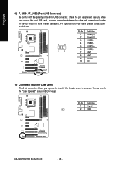
English 15) F_ USB1 / F_USB2 (Front USB Connector) Be careful with the polarity of the front USB connector. Definition 1 Signal 1 2 GND GA-945P-DS3/S3 Motherboard - 26 - Pin No. You can check the "Case Opened" status in BIOS Setup. Check the pin assignment carefully while you connect the front USB ...
English 15) F_ USB1 / F_USB2 (Front USB Connector) Be careful with the polarity of the front USB connector. Definition 1 Signal 1 2 GND GA-945P-DS3/S3 Motherboard - 26 - Pin No. You can check the "Case Opened" status in BIOS Setup. Check the pin assignment carefully while you connect the front USB ...
Manual
Page 28
English GA-945P-DS3/S3 Motherboard - 28 -
English GA-945P-DS3/S3 Motherboard - 28 -

Manual
Page 30
... POST screen at system startup, refer to the instructions on the Full Screen LOGO Show item on the screen. The Main Menu (For example: GA-945P-DS3 BIOS Ver. GA-945P-DS3/S3 Motherboard - 30 - Select the Load Optimized Defaults item in this chapter are for reference only and may differ from the exact settings for stability...
... POST screen at system startup, refer to the instructions on the Full Screen LOGO Show item on the screen. The Main Menu (For example: GA-945P-DS3 BIOS Ver. GA-945P-DS3/S3 Motherboard - 30 - Select the Load Optimized Defaults item in this chapter are for reference only and may differ from the exact settings for stability...
Manual
Page 32
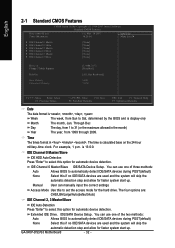
... Access Mode Use this to select this option for automatic device detection. is calculated base on the 24-hour military-time clock. Extended IDE Drive. GA-945P-DS3/S3 Motherboard - 32 - English 2-1 Standard CMOS Features Date (mm:dd:yy) Time (hh:mm:ss) CMOS Setup Utility-Copyright (C) 1984-2007 Award Software Standard CMOS Features...
... Access Mode Use this to select this option for automatic device detection. is calculated base on the 24-hour military-time clock. Extended IDE Drive. GA-945P-DS3/S3 Motherboard - 32 - English 2-1 Standard CMOS Features Date (mm:dd:yy) Time (hh:mm:ss) CMOS Setup Utility-Copyright (C) 1984-2007 Award Software Standard CMOS Features...
Manual
Page 34
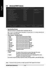
... your boot device priority by USB-FDD. USB-ZIP Select your boot device priority by USB-ZIP. LAN Select your boot device priority by LAN. GA-945P-DS3/S3 Motherboard - 34 - Capability CPU Hyper-Threading (Note) Limit CPUID Max. to exit this menu. Hard Disk Select your boot device priority by Hard Disk. If...
... your boot device priority by USB-FDD. USB-ZIP Select your boot device priority by USB-ZIP. LAN Select your boot device priority by LAN. GA-945P-DS3/S3 Motherboard - 34 - Capability CPU Hyper-Threading (Note) Limit CPUID Max. to exit this menu. Hard Disk Select your boot device priority by Hard Disk. If...
Manual
Page 36
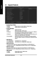
..., the motherboard allows up to ". PATA devices will auto make by the setting "On-Chip SATA Mode" and "PATA IDE Set to Ch. 0 Master/Slave. GA-945P-DS3/S3 Motherboard - 36 - On-Chip SATA Mode Disabled Auto Disable this function will auto detect. (Default value) Combined Set On-Chip SATA mode to Combined, you...
..., the motherboard allows up to ". PATA devices will auto make by the setting "On-Chip SATA Mode" and "PATA IDE Set to Ch. 0 Master/Slave. GA-945P-DS3/S3 Motherboard - 36 - On-Chip SATA Mode Disabled Auto Disable this function will auto detect. (Default value) Combined Set On-Chip SATA mode to Combined, you...
Manual
Page 38
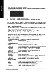
... speed Displays the approximate length of 10/100/1000Mbps in MS-DOS mode; When a Cable Problem Occurs... ECP Using Parallel port as Enhanced Parallel Port. GA-945P-DS3/S3 Motherboard - 38 - it will operate at Port..... Disabled Disable this function. Parallel Port Mode SPP Using Parallel port as Standard Parallel Port. (Default value) EPP...
... speed Displays the approximate length of 10/100/1000Mbps in MS-DOS mode; When a Cable Problem Occurs... ECP Using Parallel port as Enhanced Parallel Port. GA-945P-DS3/S3 Motherboard - 38 - it will operate at Port..... Disabled Disable this function. Parallel Port Mode SPP Using Parallel port as Standard Parallel Port. (Default value) EPP...

