Manual
Page 4
... Expansion Cards 16 1-6 I .T 44 2-8 Load Fail-Safe Defaults 46 2-9 Load Optimized Defaults 46 2-10 Set Supervisor/User Password 47 2-11 Save & Exit Setup 48 2-12 Exit Without Saving 48 - 4 - F2c 30 2-1 Standard CMOS Features 32 2-2 Advanced BIOS Features 34 2-3 IntegratedPeripherals 36 2-4 Power Management Setup 39 2-5 PnP/PCI Configurations 41 2-6 PC Health Status 42 2-7 MB Intelligent Tweaker(M.I /O Back Panel Introduction 17 1-7 Connectors Introduction 18 Chapter 2 BIOS Setup 29 The Main Menu (For example: GA-945P-DS3 BIOS...
... Expansion Cards 16 1-6 I .T 44 2-8 Load Fail-Safe Defaults 46 2-9 Load Optimized Defaults 46 2-10 Set Supervisor/User Password 47 2-11 Save & Exit Setup 48 2-12 Exit Without Saving 48 - 4 - F2c 30 2-1 Standard CMOS Features 32 2-2 Advanced BIOS Features 34 2-3 IntegratedPeripherals 36 2-4 Power Management Setup 39 2-5 PnP/PCI Configurations 41 2-6 PC Health Status 42 2-7 MB Intelligent Tweaker(M.I /O Back Panel Introduction 17 1-7 Connectors Introduction 18 Chapter 2 BIOS Setup 29 The Main Menu (For example: GA-945P-DS3 BIOS...
Manual
Page 10
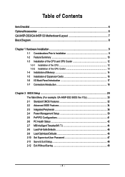
...3 PCI slots Internal Connectors Š 1 24-pin ATX power connector Š 1 4-pin ATX 12V power connector Š 1 floppy connector Š 1 IDE connector Š 4 SATA 3Gb/s connectors Š 1 CPU fan connector Š 1 system fan connector Š 1 power fan connector Š 1 northbridge fan connector Š 1 front panel connector Š 1 front audio connector Š 1 CD In connector Š 1 S/PDIF In/Out connector Š 2 USB 2.0/1.1 connectors for additional 4 ports by cables Š 1 power LED connector Š 1 Chassis Intrusion connector "*" Only the GA-945P-DS3...
...3 PCI slots Internal Connectors Š 1 24-pin ATX power connector Š 1 4-pin ATX 12V power connector Š 1 floppy connector Š 1 IDE connector Š 4 SATA 3Gb/s connectors Š 1 CPU fan connector Š 1 system fan connector Š 1 power fan connector Š 1 northbridge fan connector Š 1 front panel connector Š 1 front audio connector Š 1 CD In connector Š 1 S/PDIF In/Out connector Š 2 USB 2.0/1.1 connectors for additional 4 ports by cables Š 1 power LED connector Š 1 Chassis Intrusion connector "*" Only the GA-945P-DS3...
Manual
Page 13
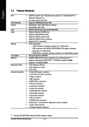
... instruction is only for Intel boxed fan) Fig. 3 Place the CPU cooler atop the CPU and make sure the Male and Female push pin are joined closely. (for heat dissipation or using extreme care when removing the CPU cooler. - 13 - If the push pin is inserted as a result of hardening of motherboard after installing. Fig. 6 Finally, please attach the power connector of the installed CPU...
... instruction is only for Intel boxed fan) Fig. 3 Place the CPU cooler atop the CPU and make sure the Male and Female push pin are joined closely. (for heat dissipation or using extreme care when removing the CPU cooler. - 13 - If the push pin is inserted as a result of hardening of motherboard after installing. Fig. 6 Finally, please attach the power connector of the installed CPU...
Manual
Page 15
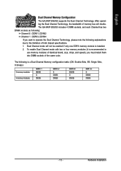
... Intel chipset specifications. 1. Hardware Installation To enable Dual Channel mode with two or four memory modules (it is recommended to operate the Dual Channel Technology, please note the following is installed. 2. The GA-945P-DS3/S3 includes 4 DIMM sockets, and each Channel has two DIMM sockets as following: Channel 0 : DDRII1, DDRII2 Channel 1 : DDRII3, DDRII4 If you want to use memory modules of identical brand, size, chips, and speed), you must install them into DIMM sockets of memory bus will...
... Intel chipset specifications. 1. Hardware Installation To enable Dual Channel mode with two or four memory modules (it is recommended to operate the Dual Channel Technology, please note the following is installed. 2. The GA-945P-DS3/S3 includes 4 DIMM sockets, and each Channel has two DIMM sockets as following: Channel 0 : DDRII1, DDRII2 Channel 1 : DDRII3, DDRII4 If you want to use memory modules of identical brand, size, chips, and speed), you must install them into DIMM sockets of memory bus will...
Manual
Page 18
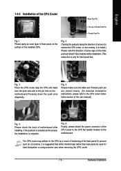
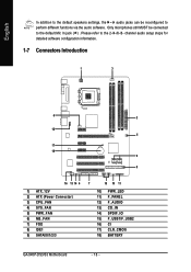
Please refer to the 2-/4-/6-/8- channel audio setup steps for detailed software configuration information. 1-7 Connectors Introduction 1 3 6 2 12 5 17 18 9 8 16 13 14 4 1) ATX_12V 2) ATX (Power Connector) 3) CPU_FAN 4) SYS_FAN 5) PWR_FAN 6) NB_FAN 7) FDD 8) IDE1 9) SATAII0/1/2/3 7 15 10 11 10) PWR_LED 11) F_PANEL 12) F_AUDIO 13) CD_IN 14) SPDIF_IO 15) F_USB1/F_USB2 16) CI 17) CLR_CMOS 18) BATTERY GA-945P-DS3/S3 Motherboard - 18 - Only microphones still MUST be...
Please refer to the 2-/4-/6-/8- channel audio setup steps for detailed software configuration information. 1-7 Connectors Introduction 1 3 6 2 12 5 17 18 9 8 16 13 14 4 1) ATX_12V 2) ATX (Power Connector) 3) CPU_FAN 4) SYS_FAN 5) PWR_FAN 6) NB_FAN 7) FDD 8) IDE1 9) SATAII0/1/2/3 7 15 10 11 10) PWR_LED 11) F_PANEL 12) F_AUDIO 13) CD_IN 14) SPDIF_IO 15) F_USB1/F_USB2 16) CI 17) CLR_CMOS 18) BATTERY GA-945P-DS3/S3 Motherboard - 18 - Only microphones still MUST be...
Manual
Page 20
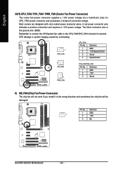
... are designed with color-coded power connector wires. Definition 1 GND 2 +12V 3 Sense 6) NB_FAN (Chip Fan Power Connector) The chip fan will not work if you install it in the wrong direction and sometimes the chip fan will be damaged. Definition 1 GND 1 2 +12V 3 NC GA-945P-DS3/S3 Motherboard - 20 - The black connector wire is the ground wire (GND). Remember to connect the CPU/system fan cable to the CPU_FAN/SYS_FAN connector to prevent CPU damage or system...
... are designed with color-coded power connector wires. Definition 1 GND 2 +12V 3 Sense 6) NB_FAN (Chip Fan Power Connector) The chip fan will not work if you install it in the wrong direction and sometimes the chip fan will be damaged. Definition 1 GND 1 2 +12V 3 NC GA-945P-DS3/S3 Motherboard - 20 - The black connector wire is the ground wire (GND). Remember to connect the CPU/system fan cable to the CPU_FAN/SYS_FAN connector to prevent CPU damage or system...
Manual
Page 22
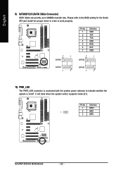
Pin No. GA-945P-DS3/S3 Motherboard - 22 - Please refer to the BIOS setting for the Serial ATA and install the proper driver in order to work properly. 7 1 SATAII0 Pin No. 1 2 3 4 5 6 7 Definition GND TXP TXN GND RXN RXP GND 7 1 SATAII2 SATAII1 1 7 SATAII3 1 7 10) PWR_LED The PWR_LED connector is connected with the system power indicator to 300MB/s transfer rate. It will blink when the system enters suspend mode (S1...
Pin No. GA-945P-DS3/S3 Motherboard - 22 - Please refer to the BIOS setting for the Serial ATA and install the proper driver in order to work properly. 7 1 SATAII0 Pin No. 1 2 3 4 5 6 7 Definition GND TXP TXN GND RXN RXP GND 7 1 SATAII2 SATAII1 1 7 SATAII3 1 7 10) PWR_LED The PWR_LED connector is connected with the system power indicator to 300MB/s transfer rate. It will blink when the system enters suspend mode (S1...
Manual
Page 23
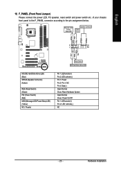
... IDE Hard Disk Active LED HD (IDE Hard Disk Active LED) (Blue) SPEAK (Speaker Connector) (Amber) RES (Reset Switch) (Green) PW (Power Switch) (Red) MSG (Message LED/Power/Sleep LED) (Yellow) NC ( Purple) Pin 1: LED anode(+) Pin 2: LED cathode(-) Pin 1: Power Pin 2- Pin 3: NC Pin 4: Data(-) Open: Normal Close: Reset Hardware System Open: Normal Close: Power On/Off Pin 1: LED anode(+) Pin 2: LED cathode(-) NC - 23 - Hardware Installation PW+ PWSPEAK+ SPEAK- 2 20 1 19 HD+ HD- Message LED/ Power/ Sleep LED Speaker Connector Power Switch MSG+ MSG- of your chassis front panel...
... IDE Hard Disk Active LED HD (IDE Hard Disk Active LED) (Blue) SPEAK (Speaker Connector) (Amber) RES (Reset Switch) (Green) PW (Power Switch) (Red) MSG (Message LED/Power/Sleep LED) (Yellow) NC ( Purple) Pin 1: LED anode(+) Pin 2: LED cathode(-) Pin 1: Power Pin 2- Pin 3: NC Pin 4: Data(-) Open: Normal Close: Reset Hardware System Open: Normal Close: Power On/Off Pin 1: LED anode(+) Pin 2: LED cathode(-) NC - 23 - Hardware Installation PW+ PWSPEAK+ SPEAK- 2 20 1 19 HD+ HD- Message LED/ Power/ Sleep LED Speaker Connector Power Switch MSG+ MSG- of your chassis front panel...
Manual
Page 24
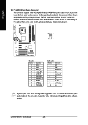
... you wish to use the front audio function, connect the front panel audio module to support HD Audio. Definition 1 MIC 2 GND 3 MIC Power 4 NC 5 Line Out (R) 6 NC 7 NC 8 No Pin 9 Line Out (L) 10 NC By default, the audio driver is configured to this connector, please refer to work or even damage it. GA-945P-DS3/S3 Motherboard - 24 - For optional front panel audio module, please contact your chassis manufacturer. 10 9 2 1 HD Audio: Pin No. 1 2 3 4 5 6 7 8 9 10...
... you wish to use the front audio function, connect the front panel audio module to support HD Audio. Definition 1 MIC 2 GND 3 MIC Power 4 NC 5 Line Out (R) 6 NC 7 NC 8 No Pin 9 Line Out (L) 10 NC By default, the audio driver is configured to this connector, please refer to work or even damage it. GA-945P-DS3/S3 Motherboard - 24 - For optional front panel audio module, please contact your chassis manufacturer. 10 9 2 1 HD Audio: Pin No. 1 2 3 4 5 6 7 8 9 10...
Manual
Page 30
...S3 Motherboard - 30 - The Main Menu (For example: GA-945P-DS3 BIOS Ver. CMOS Setup Utility-Copyright (C) 1984-2007 Award Software ` Standard CMOS Features ` Advanced BIOS Features ` Integrated Peripherals ` Power Management Setup ` PnP/PCI Configurations ` PC Health Status ` MB Intelligent Tweaker(M.I.T.) Load Fail-Safe Defaults Load Optimized Defaults Set Supervisor Password Set User Password Save & Exit Setup Exit Without Saving ESC: Quit F8: Q-Flash KLJI: Select Item F10: Save & Exit Setup Time, Date, Hard Disk Type... 1. This action makes the system reset to accept or enter...
...S3 Motherboard - 30 - The Main Menu (For example: GA-945P-DS3 BIOS Ver. CMOS Setup Utility-Copyright (C) 1984-2007 Award Software ` Standard CMOS Features ` Advanced BIOS Features ` Integrated Peripherals ` Power Management Setup ` PnP/PCI Configurations ` PC Health Status ` MB Intelligent Tweaker(M.I.T.) Load Fail-Safe Defaults Load Optimized Defaults Set Supervisor Password Set User Password Save & Exit Setup Exit Without Saving ESC: Quit F8: Q-Flash KLJI: Select Item F10: Save & Exit Setup Time, Date, Hard Disk Type... 1. This action makes the system reset to accept or enter...
Manual
Page 32
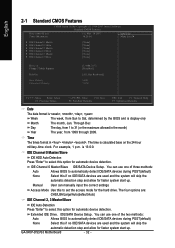
... , , , . IDE Channel 0 Master/Slave IDE HDD Auto-Detection Press "Enter" to automatically detect IDE/SATA devices during POST(default) None Select this if no IDE/SATA devices are used and the system will skip the automatic detection step and allow for automatic device detection. You can manually input the correct settings Access Mode Use this option for faster system start up . Through Dec The day, from 1999 through 2099. IDE Channel 0 Master/Slave IDE/SATA Device Setup. GA-945P-DS3/S3 Motherboard - 32...
... , , , . IDE Channel 0 Master/Slave IDE HDD Auto-Detection Press "Enter" to automatically detect IDE/SATA devices during POST(default) None Select this if no IDE/SATA devices are used and the system will skip the automatic detection step and allow for automatic device detection. You can manually input the correct settings Access Mode Use this option for faster system start up . Through Dec The day, from 1999 through 2099. IDE Channel 0 Master/Slave IDE/SATA Device Setup. GA-945P-DS3/S3 Motherboard - 32...
Manual
Page 37
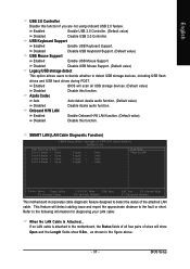
... Setup Utility-Copyright (C) 1984-2007 Award Software SMART LAN Start detecting at Port..... Enabled BIOS will show Open and the Length fields show 0.0m, as shown in the figure above. - 37 - If no LAN cable is attached to the motherboard, the Status fields of all USB storage devices. (Default value) Disabled Disable this function. Disabled Disable USB Keyboard Support. (Default value) USB Mouse Support Enabled Enable USB Mouse Support. Onboard H/W LAN Enabled Enable Onboard H/W LAN function. (Default value) Disabled Disable this function if you are not using...
... Setup Utility-Copyright (C) 1984-2007 Award Software SMART LAN Start detecting at Port..... Enabled BIOS will show Open and the Length fields show 0.0m, as shown in the figure above. - 37 - If no LAN cable is attached to the motherboard, the Status fields of all USB storage devices. (Default value) Disabled Disable this function. Disabled Disable USB Keyboard Support. (Default value) USB Mouse Support Enabled Enable USB Mouse Support. Onboard H/W LAN Enabled Enable Onboard H/W LAN function. (Default value) Disabled Disable this function if you are not using...
Manual
Page 42
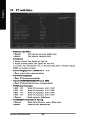
.... GA-945P-DS3/S3 Motherboard - 42 - English 2-6 PC Health Status CMOS Setup Utility-Copyright (C) 1984-2007 Award Software PC Health Status Reset Case Open Status Case Opened Vcore DDR18V +3.3V +12V Current CPU Temperature Current CPU FAN Speed Current POWER FAN Speed Current SYSTEM FAN Speed CPU Warning Temperature CPU FAN Fail Warning POWER FAN Fail Warning SYSTEM FAN Fail Warning CPU Smart FAN Control CPU Smart FAN Mode [Disabled] No OK OK OK OK 47oC 3375 RPM 0 RPM 0 RPM [Disabled] [Disabled] [Disabled] [Disabled] [Enabled] [Auto] Item Help Menu Level` KLJI: Move Enter: Select...
.... GA-945P-DS3/S3 Motherboard - 42 - English 2-6 PC Health Status CMOS Setup Utility-Copyright (C) 1984-2007 Award Software PC Health Status Reset Case Open Status Case Opened Vcore DDR18V +3.3V +12V Current CPU Temperature Current CPU FAN Speed Current POWER FAN Speed Current SYSTEM FAN Speed CPU Warning Temperature CPU FAN Fail Warning POWER FAN Fail Warning SYSTEM FAN Fail Warning CPU Smart FAN Control CPU Smart FAN Mode [Disabled] No OK OK OK OK 47oC 3375 RPM 0 RPM 0 RPM [Disabled] [Disabled] [Disabled] [Disabled] [Enabled] [Auto] Item Help Menu Level` KLJI: Move Enter: Select...
Manual
Page 47
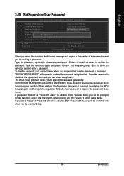
... Type the password, up to abort the selection and not enter a password. To disable password, just press when you to specify two separate passwords: SUPERVISOR PASSWORD and a USER PASSWORD. The BIOS Setup program allows you are prompted to enter password. English 2-10 Set Supervisor/User Password CMOS Setup Utility-Copyright (C) 1984-2007 Award Software ` Standard CMOS Features ` Advanced BIOS Features ` Integrated Peripherals ` Power Management Setup ` PnP/PCI ConfigurationEsnter Password: ` PC Health Status ` MB Intelligent Tweaker(M.I.T.) Load Fail-Safe Defaults Load Optimized...
... Type the password, up to abort the selection and not enter a password. To disable password, just press when you to specify two separate passwords: SUPERVISOR PASSWORD and a USER PASSWORD. The BIOS Setup program allows you are prompted to enter password. English 2-10 Set Supervisor/User Password CMOS Setup Utility-Copyright (C) 1984-2007 Award Software ` Standard CMOS Features ` Advanced BIOS Features ` Integrated Peripherals ` Power Management Setup ` PnP/PCI ConfigurationEsnter Password: ` PC Health Status ` MB Intelligent Tweaker(M.I.T.) Load Fail-Safe Defaults Load Optimized...
Manual
Page 48
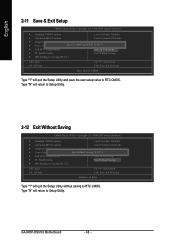
... Setup Utility. Type "N" will return to Setup Utility. 2-12 Exit Without Saving CMOS Setup Utility-Copyright (C) 1984-2007 Award Software ` Standard CMOS Features ` Advanced BIOS Features ` Integrated Peripherals ` Power Management Setup ` PnP/PCI Configurations ` PC Health Status ` MB Intelligent Tweaker(M.I .T.) ESC: Quit F8: Q-Flash KLJI: Select Item F10: Save & Exit Setup Save Data to CMOS Type "Y" will quit the Setup Utility and save the user setup value to RTC CMOS. GA-945P-DS3/S3 Motherboard - 48 - Type "N" will quit the Setup Utility...
... Setup Utility. Type "N" will return to Setup Utility. 2-12 Exit Without Saving CMOS Setup Utility-Copyright (C) 1984-2007 Award Software ` Standard CMOS Features ` Advanced BIOS Features ` Integrated Peripherals ` Power Management Setup ` PnP/PCI Configurations ` PC Health Status ` MB Intelligent Tweaker(M.I .T.) ESC: Quit F8: Q-Flash KLJI: Select Item F10: Save & Exit Setup Save Data to CMOS Type "Y" will quit the Setup Utility and save the user setup value to RTC CMOS. GA-945P-DS3/S3 Motherboard - 48 - Type "N" will quit the Setup Utility...
Manual
Page 49
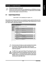
... your CD-ROM drive, the driver CD-title will auto start and show a question mark "?" For USB2.0 driver support under "Device Manager". Install Drivers or you can press "Xpress Install" to install all the drivers that recommended to install. System will reboot automatically after install the drivers, afterward you can install others application. After install Windows Service Pack, it will restart your system automatically. Some device drivers will show the installation guide. Please remove the...
... your CD-ROM drive, the driver CD-title will auto start and show a question mark "?" For USB2.0 driver support under "Device Manager". Install Drivers or you can press "Xpress Install" to install all the drivers that recommended to install. System will reboot automatically after install the drivers, afterward you can install others application. After install Windows Service Pack, it will restart your system automatically. Some device drivers will show the installation guide. Please remove the...
Manual
Page 54
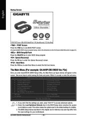
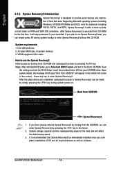
... power-on PATA and SATA IDE controllers. GA-945P-DS3/S3 Motherboard . . . . - 54 - English 4-1-2 Xpress Recovery2 Introduction Xpress Recovery2 is executed from CD-ROM for 945P-DS3 F2c . . . . :BIOS Setup/Q-Flash : XpressRecovery2 : Boot Menu : Qflash 01/31/2007-I945-6A79TG0AC-00 : Xpress Recovery2 1. System requirements: 1. Insert the provided driver CD into your hard disk. After the steps above are completed, subsequent access to enter Xpress Recovery2 without the CD-ROM. Intel P945 BIOS...
... power-on PATA and SATA IDE controllers. GA-945P-DS3/S3 Motherboard . . . . - 54 - English 4-1-2 Xpress Recovery2 Introduction Xpress Recovery2 is executed from CD-ROM for 945P-DS3 F2c . . . . :BIOS Setup/Q-Flash : XpressRecovery2 : Boot Menu : Qflash 01/31/2007-I945-6A79TG0AC-00 : Xpress Recovery2 1. System requirements: 1. Insert the provided driver CD into your hard disk. After the steps above are completed, subsequent access to enter Xpress Recovery2 without the CD-ROM. Intel P945 BIOS...
Manual
Page 56
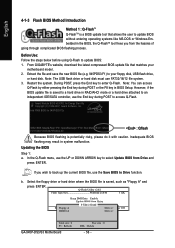
... saved to a hard drive in RAID/AHCI mode or a hard drive attached to an independent IDE/SATA controller, use the Save BIOS to Drive function. Note: The USB flash drive or hard disk must use the UP or DOWN ARROW key to select Update BIOS from Drive Sa0vefilBeI(Os)SfotounDdrive EnteFr l:oRppuyn A :Move ESC:Reset :Power Off HDD 0-0 Total size : 0 F5 : Refresh GA-945P-DS3/S3 Motherboard . . . . However, if the BIOS update file is a BIOS update tool that matches your floppy disk, USB flash drive, or hard disk. Q-Flash Utility v2.02 Flash Type/Size Winbond 25X40 512K...
... saved to a hard drive in RAID/AHCI mode or a hard drive attached to an independent IDE/SATA controller, use the Save BIOS to Drive function. Note: The USB flash drive or hard disk must use the UP or DOWN ARROW key to select Update BIOS from Drive Sa0vefilBeI(Os)SfotounDdrive EnteFr l:oRppuyn A :Move ESC:Reset :Power Off HDD 0-0 Total size : 0 F5 : Refresh GA-945P-DS3/S3 Motherboard . . . . However, if the BIOS update file is a BIOS update tool that matches your floppy disk, USB flash drive, or hard disk. Q-Flash Utility v2.02 Flash Type/Size Winbond 25X40 512K...
Manual
Page 58
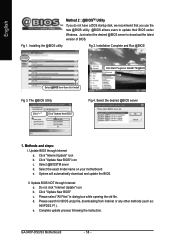
... and Run @BIOS Click Start/ Programs/ GIGABYTE/@BIOS Select @BIOS item than click Install Fig 3. Select the desired @BIOS server Click "3" Click "Update New BIOS" 1. Click "Update New BIOS" icon c. System will automatically download and update the BIOS. Complete update process following the instruction. Methods and steps: I. Click "Update New BIOS" c. Select the exact model name on your motherboard e. II. Update BIOS NOT through Internet a. GA-945P-DS3/S3 Motherboard . . . . - 58 - d. Please select "All Files" in dialog...
... and Run @BIOS Click Start/ Programs/ GIGABYTE/@BIOS Select @BIOS item than click Install Fig 3. Select the desired @BIOS server Click "3" Click "Update New BIOS" 1. Click "Update New BIOS" icon c. System will automatically download and update the BIOS. Complete update process following the instruction. Methods and steps: I. Click "Update New BIOS" c. Select the exact model name on your motherboard e. II. Update BIOS NOT through Internet a. GA-945P-DS3/S3 Motherboard . . . . - 58 - d. Please select "All Files" in dialog...
Manual
Page 65
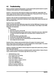
... these options. AWARD BIOS Beep Codes 1 short: System boots successfully 2 short: CMOS setting error 1 long 1 short: DRAM or M/B error 1 long 2 short: Monitor or display card error 1 long 3 short: Keyboard error 1 long 9 short: BIOS ROM error Continuous long beeps: DRAM error Continuous short beeps: Power error - 65 - English 4-2 Troubleshooting Below is a collection of electricity is kept on standby after computer shuts down and that were included in the manual. To check general asked questions. Questions 2: Why is the light of my keyboard/optical mouse still on -board battery...
... these options. AWARD BIOS Beep Codes 1 short: System boots successfully 2 short: CMOS setting error 1 long 1 short: DRAM or M/B error 1 long 2 short: Monitor or display card error 1 long 3 short: Keyboard error 1 long 9 short: BIOS ROM error Continuous long beeps: DRAM error Continuous short beeps: Power error - 65 - English 4-2 Troubleshooting Below is a collection of electricity is kept on standby after computer shuts down and that were included in the manual. To check general asked questions. Questions 2: Why is the light of my keyboard/optical mouse still on -board battery...


