Manual
Page 1
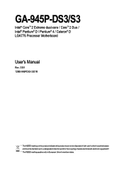
GA-945P-DS3/S3 Intel® CoreTM 2 Extreme dual-core / CoreTM 2 Duo / Intel® Pentium® D / Pentium® 4 / Celeron® D LGA775 Processor Motherboard User's Manual Rev. 3301 12ME-945PDS3-3301R * The WEEE marking on the product indicates this product must not be disposed of with user's other household waste and must be handed over to a designated collection point for the recycling of waste electrical and electronic equipment!! * The WEEE marking applies only in European Union's member states.
GA-945P-DS3/S3 Intel® CoreTM 2 Extreme dual-core / CoreTM 2 Duo / Intel® Pentium® D / Pentium® 4 / Celeron® D LGA775 Processor Motherboard User's Manual Rev. 3301 12ME-945PDS3-3301R * The WEEE marking on the product indicates this product must not be disposed of with user's other household waste and must be handed over to a designated collection point for the recycling of waste electrical and electronic equipment!! * The WEEE marking applies only in European Union's member states.
Manual
Page 2
Motherboard GA-945P-DS3/GA-945P-S3 Oct. 27, 2006 Motherboard GA-945P-DS3/ GA-945P-S3 Oct. 27, 2006
Motherboard GA-945P-DS3/GA-945P-S3 Oct. 27, 2006 Motherboard GA-945P-DS3/ GA-945P-S3 Oct. 27, 2006
Manual
Page 4
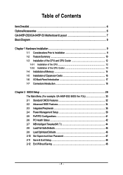
Table of Contents ItemChecklist ...6 OptionalAccessories ...6 GA-945P-DS3/GA-945P-S3 Motherboard Layout 7 Block Diagram ...8 Chapter 1 Hardware Installation 9 1-1 Considerations Prior to Installation 9 1-2 Feature Summary 10 1-3 Installation of the CPU and CPU Cooler 12 1-3-1 Installation of the CPU ... Configurations 41 2-6 PC Health Status 42 2-7 MB Intelligent Tweaker(M.I /O Back Panel Introduction 17 1-7 Connectors Introduction 18 Chapter 2 BIOS Setup 29 The Main Menu (For example: GA-945P-DS3 BIOS Ver.
Table of Contents ItemChecklist ...6 OptionalAccessories ...6 GA-945P-DS3/GA-945P-S3 Motherboard Layout 7 Block Diagram ...8 Chapter 1 Hardware Installation 9 1-1 Considerations Prior to Installation 9 1-2 Feature Summary 10 1-3 Installation of the CPU and CPU Cooler 12 1-3-1 Installation of the CPU ... Configurations 41 2-6 PC Health Status 42 2-7 MB Intelligent Tweaker(M.I /O Back Panel Introduction 17 1-7 Connectors Introduction 18 Chapter 2 BIOS Setup 29 The Main Menu (For example: GA-945P-DS3 BIOS Ver.
Manual
Page 7
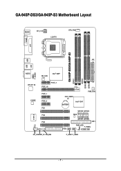
GA-945P-DS3/GA-945P-S3 Motherboard Layout KB_MS ATX_12V LGA775 CPU_FAN COMA LPT GA-945P-DS3/GA-945P-S3 DDRII1 DDRII2 DDRII3 DDRII4 USB USB LAN ATX F_AUDIO AUDIO NB_FAN Intel® 945P RTL8111B CODEC CI IT8718 PCIE_16 PCIE_3 PCIE_1 PCIE_2 PCI1 PCI2 PCI3 CD_IN SPDIF_IO SYS_FAN CLR_CMOS BATTERY Intel® ICH7 PWR_FAN SATAII0 SATAII2 BIOS SATAII1 SATAII3 IDE1 PWR_LED F_PANEL FDD F_USB1 F_USB2 - 7 -
GA-945P-DS3/GA-945P-S3 Motherboard Layout KB_MS ATX_12V LGA775 CPU_FAN COMA LPT GA-945P-DS3/GA-945P-S3 DDRII1 DDRII2 DDRII3 DDRII4 USB USB LAN ATX F_AUDIO AUDIO NB_FAN Intel® 945P RTL8111B CODEC CI IT8718 PCIE_16 PCIE_3 PCIE_1 PCIE_2 PCI1 PCI2 PCI3 CD_IN SPDIF_IO SYS_FAN CLR_CMOS BATTERY Intel® ICH7 PWR_FAN SATAII0 SATAII2 BIOS SATAII1 SATAII3 IDE1 PWR_LED F_PANEL FDD F_USB1 F_USB2 - 7 -
Manual
Page 8
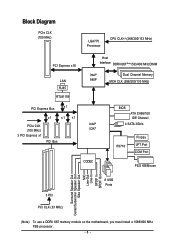
...) LGA775 Processor CPU CLK+/-(266/200/133 MHz) PCI Express x16 LAN RJ45 RTL8111B Host Interface DDRII 667(Note)/533/400 MHz DIMM Intel® 945P Dual Channel Memory MCH CLK (266/200/133 MHz) PCI Express Bus x1 x1 x1 x1 PCIe CLK Intel® (100 MHz) ICH7 3 PCI Express... MIC Line-Out Line-In SPDIF In SPDIF Out 3 PCI PCI CLK (33 MHz) 8 USB Ports (Note) To use a DDRII 667 memory module on the motherboard, you must install a 1066/800 MHz FSB processor. - 8 -
...) LGA775 Processor CPU CLK+/-(266/200/133 MHz) PCI Express x16 LAN RJ45 RTL8111B Host Interface DDRII 667(Note)/533/400 MHz DIMM Intel® 945P Dual Channel Memory MCH CLK (266/200/133 MHz) PCI Express Bus x1 x1 x1 x1 PCIe CLK Intel® (100 MHz) ICH7 3 PCI Express... MIC Line-Out Line-In SPDIF In SPDIF Out 3 PCI PCI CLK (33 MHz) 8 USB Ports (Note) To use a DDRII 667 memory module on the motherboard, you must install a 1066/800 MHz FSB processor. - 8 -
Manual
Page 9
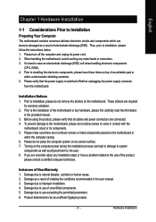
...Hardware Installation Instances of uncertified components. 5. English Chapter 1 Hardware Installation 1-1 Considerations Prior to Installation Preparing Your Computer The motherboard contains numerous delicate electronic circuits and components which can lead to damage to system components as well as physical harm to...related to come in the provided manual. 3. Prior to be an unofficial Gigabyte product. - 9 - To prevent damage to the motherboard, please do not remove the stickers on the motherboard. Product determined to installation, please do not allow screws to the use ...
...Hardware Installation Instances of uncertified components. 5. English Chapter 1 Hardware Installation 1-1 Considerations Prior to Installation Preparing Your Computer The motherboard contains numerous delicate electronic circuits and components which can lead to damage to system components as well as physical harm to...related to come in the provided manual. 3. Prior to be an unofficial Gigabyte product. - 9 - To prevent damage to the motherboard, please do not remove the stickers on the motherboard. Product determined to installation, please do not allow screws to the use ...
Manual
Page 10
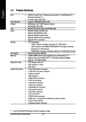
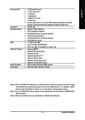
...® 4/Celeron® D Š L2 cache varies with CPU Front Side Bus Š Supports 1066/800/533 MHz FSB Chipset Š Northbridge: Intel® 945P Express Chipset Š Southbridge: Intel® ICH7 LAN Š Onboard RTL8111B chip (10/100/1000 Mbit) Audio Š Onboard Realtek ALC888 chip Š Supports High... Š 1 S/PDIF In/Out connector Š 2 USB 2.0/1.1 connectors for additional 4 ports by cables Š 1 power LED connector Š 1 Chassis Intrusion connector "*" Only the GA-945P-DS3 adopts All-Solid Capacitor design. GA-945P-DS3/S3 Motherboard - 10 -
...® 4/Celeron® D Š L2 cache varies with CPU Front Side Bus Š Supports 1066/800/533 MHz FSB Chipset Š Northbridge: Intel® 945P Express Chipset Š Southbridge: Intel® ICH7 LAN Š Onboard RTL8111B chip (10/100/1000 Mbit) Audio Š Onboard Realtek ALC888 chip Š Supports High... Š 1 S/PDIF In/Out connector Š 2 USB 2.0/1.1 connectors for additional 4 ports by cables Š 1 power LED connector Š 1 Chassis Intrusion connector "*" Only the GA-945P-DS3 adopts All-Solid Capacitor design. GA-945P-DS3/S3 Motherboard - 10 -
Manual
Page 11
..., a certain amount of memory size will instead be shown as 3.xx GB memory during system startup. (Note 2) To use a DDRII 667 memory module on the motherboard, you must install a 1066/800 MHz FSB processor. (Note 3) EasyTune functions may vary depending on different...
..., a certain amount of memory size will instead be shown as 3.xx GB memory during system startup. (Note 2) To use a DDRII 667 memory module on the motherboard, you must install a 1066/800 MHz FSB processor. (Note 3) EasyTune functions may vary depending on different...
Manual
Page 12
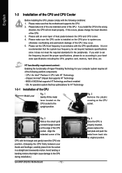
...your thumb and forefinger, carefully place it into the socket in a straight and downwards motion. Chipset: An Intel® Chipset that the motherboard supports the CPU. 2. OS: An operation system that the system bus frequency be set the CPU host frequency in the wrong direction, ...gently insert the CPU into its original position. Please set beyond the proper specifications, please do so according to the CPU during installation.) GA-945P-DS3/S3 Motherboard - 12 - It is properly inserted, please replace the load plate and push the metal lever back into position. (Grasping the ...
...your thumb and forefinger, carefully place it into the socket in a straight and downwards motion. Chipset: An Intel® Chipset that the motherboard supports the CPU. 2. OS: An operation system that the system bus frequency be set the CPU host frequency in the wrong direction, ...gently insert the CPU into its original position. Please set beyond the proper specifications, please do so according to the CPU during installation.) GA-945P-DS3/S3 Motherboard - 12 - It is properly inserted, please replace the load plate and push the metal lever back into position. (Grasping the ...
Manual
Page 13
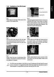
...direction of arrow is to remove the CPU cooler, on the contrary, is to install.) Please note the direction of motherboard after installing. If the push pin is inserted as a result of hardening of the installed CPU. The CPU cooler may... adhere to the pin hole on the motherboard.Pressing down the push pins diagonally. English 1-3-2 Installation of the CPU Cooler Male Push Pin The top of Female Push ...closely. (for detailed installation instructions, please refer to the CPU fan header located on the motherboard.
...direction of arrow is to remove the CPU cooler, on the contrary, is to install.) Please note the direction of motherboard after installing. If the push pin is inserted as a result of hardening of the installed CPU. The CPU cooler may... adhere to the pin hole on the motherboard.Pressing down the push pins diagonally. English 1-3-2 Installation of the CPU Cooler Male Push Pin The top of Female Push ...closely. (for detailed installation instructions, please refer to the CPU fan header located on the motherboard.
Manual
Page 14
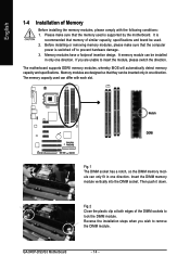
... DDRII memory modules, whereby BIOS will automatically detect memory capacity and specifications. It is supported by the motherboard. A memory module can be installed in only one direction. The memory capacity used . 2. Notch DDRII Fig.1 The DIMM socket has a notch...wish to remove the DIMM module. Reverse the installation steps when you are designed so that they can be inserted only in one direction. GA-945P-DS3/S3 Motherboard - 14 - English 1-4 Installation of the DIMM sockets to lock the DIMM module. Please make sure that memory of similar capacity, ...
... DDRII memory modules, whereby BIOS will automatically detect memory capacity and specifications. It is supported by the motherboard. A memory module can be installed in only one direction. The memory capacity used . 2. Notch DDRII Fig.1 The DIMM socket has a notch...wish to remove the DIMM module. Reverse the installation steps when you are designed so that they can be inserted only in one direction. GA-945P-DS3/S3 Motherboard - 14 - English 1-4 Installation of the DIMM sockets to lock the DIMM module. Please make sure that memory of similar capacity, ...
Manual
Page 16
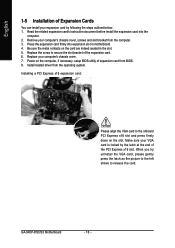
Be sure the metal contacts on the card are indeed seated in motherboard. 4. Install related driver from BIOS. 8. Press the expansion card firmly into the computer. 2. Installing a PCI Express x16 expansion card: Please align the VGA card to... computer. 3. Remove your computer's chassis cover. 7. Read the related expansion card's instruction document before install the expansion card into expansion slot in the slot. 5. GA-945P-DS3/S3 Motherboard - 16 - Power on the slot. When you try uninstall the VGA card, please gently press the latch as the picture to the left shows to...
Be sure the metal contacts on the card are indeed seated in motherboard. 4. Install related driver from BIOS. 8. Press the expansion card firmly into the computer. 2. Installing a PCI Express x16 expansion card: Please align the VGA card to... computer. 3. Remove your computer's chassis cover. 7. Read the related expansion card's instruction document before install the expansion card into expansion slot in the slot. 5. GA-945P-DS3/S3 Motherboard - 16 - Power on the slot. When you try uninstall the VGA card, please gently press the latch as the picture to the left shows to...
Manual
Page 18
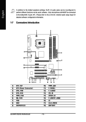
... 7) FDD 8) IDE1 9) SATAII0/1/2/3 7 15 10 11 10) PWR_LED 11) F_PANEL 12) F_AUDIO 13) CD_IN 14) SPDIF_IO 15) F_USB1/F_USB2 16) CI 17) CLR_CMOS 18) BATTERY GA-945P-DS3/S3 Motherboard - 18 -
... 7) FDD 8) IDE1 9) SATAII0/1/2/3 7 15 10 11 10) PWR_LED 11) F_PANEL 12) F_AUDIO 13) CD_IN 14) SPDIF_IO 15) F_USB1/F_USB2 16) CI 17) CLR_CMOS 18) BATTERY GA-945P-DS3/S3 Motherboard - 18 -
Manual
Page 19
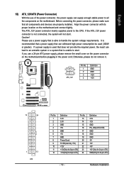
... +5V +5V +5V (Only for 24-pin ATX) GND(Only for 24-pin ATX) - 19 - Align the power connector with its proper location on the motherboard before plugging in the power cord; Please use a power supply that is recommended that a power supply that all the components on the... motherboard. English 1/2) ATX_12V/ATX (Power Connector) With the use of the power connector, the power supply can supply enough stable power to the CPU. Before connecting ...
... +5V +5V +5V (Only for 24-pin ATX) GND(Only for 24-pin ATX) - 19 - Align the power connector with its proper location on the motherboard before plugging in the power cord; Please use a power supply that is recommended that a power supply that all the components on the... motherboard. English 1/2) ATX_12V/ATX (Power Connector) With the use of the power connector, the power supply can supply enough stable power to the CPU. Before connecting ...
Manual
Page 20
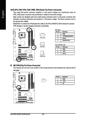
The black connector wire is the ground wire (GND). Definition 1 GND 1 2 +12V 3 NC GA-945P-DS3/S3 Motherboard - 20 - Remember to connect the CPU/system fan cable to the CPU_FAN/SYS_FAN connector to prevent CPU damage or system hanging caused by overheating. 1 CPU_FAN ...
The black connector wire is the ground wire (GND). Definition 1 GND 1 2 +12V 3 NC GA-945P-DS3/S3 Motherboard - 20 - Remember to connect the CPU/system fan cable to the CPU_FAN/SYS_FAN connector to prevent CPU damage or system hanging caused by overheating. 1 CPU_FAN ...
Manual
Page 22
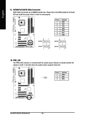
... work properly. 7 1 SATAII0 Pin No. 1 2 3 4 5 6 7 Definition GND TXP TXN GND RXN RXP GND 7 1 SATAII2 SATAII1 1 7 SATAII3 1 7 10) PWR_LED The PWR_LED connector is on/off. GA-945P-DS3/S3 Motherboard - 22 - English 9) SATAII0/1/2/3 (SATA 3Gb/s Connector) SATA 3Gb/s can provide up to indicate whether the system is connected with the system power indicator to 300MB...
... work properly. 7 1 SATAII0 Pin No. 1 2 3 4 5 6 7 Definition GND TXP TXN GND RXN RXP GND 7 1 SATAII2 SATAII1 1 7 SATAII3 1 7 10) PWR_LED The PWR_LED connector is on/off. GA-945P-DS3/S3 Motherboard - 22 - English 9) SATAII0/1/2/3 (SATA 3Gb/s Connector) SATA 3Gb/s can provide up to indicate whether the system is connected with the system power indicator to 300MB...
Manual
Page 24
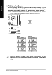
If you connect the front panel audio module. GA-945P-DS3/S3 Motherboard - 24 - Incorrect connection between the module and connector will make the audio device unable to support HD Audio. Definition 1 MIC 2 GND 3 MIC Power 4 NC 5 Line ...
If you connect the front panel audio module. GA-945P-DS3/S3 Motherboard - 24 - Incorrect connection between the module and connector will make the audio device unable to support HD Audio. Definition 1 MIC 2 GND 3 MIC Power 4 NC 5 Line ...
Manual
Page 26
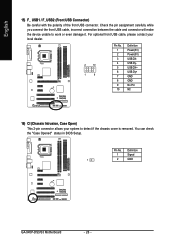
... No Pin NC 16) CI (Chassis Intrusion, Case Open) This 2-pin connector allows your system to work or even damage it. Definition 1 Signal 1 2 GND GA-945P-DS3/S3 Motherboard - 26 - English 15) F_ USB1 / F_USB2 (Front USB Connector) Be careful with the polarity of the front USB connector. You can check the "Case Opened...
... No Pin NC 16) CI (Chassis Intrusion, Case Open) This 2-pin connector allows your system to work or even damage it. Definition 1 Signal 1 2 GND GA-945P-DS3/S3 Motherboard - 26 - English 15) F_ USB1 / F_USB2 (Front USB Connector) Be careful with the polarity of the front USB connector. You can check the "Case Opened...
Manual
Page 28
English GA-945P-DS3/S3 Motherboard - 28 -
English GA-945P-DS3/S3 Motherboard - 28 -
Manual
Page 29
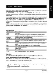
... Menu and Option Page Setup Menu Item Help Restore the previous CMOS value from CMOS, only for Main Menu Main Menu The on the motherboard supplies the necessary power to use and the possible selections for the highlighted item. CONTROL KEYS Enter> Move to activate certain system features.... a CMOS SETUP utility which allows user to configure required settings or to select item Select Item Main Menu - If you to a new BIOS, either Gigabyte's Q-Flash or @BIOS utility can enter the BIOS setup screen by pressing "Ctrl + F1". You can be used. Q-Flash allows the user to ...
... Menu and Option Page Setup Menu Item Help Restore the previous CMOS value from CMOS, only for Main Menu Main Menu The on the motherboard supplies the necessary power to use and the possible selections for the highlighted item. CONTROL KEYS Enter> Move to activate certain system features.... a CMOS SETUP utility which allows user to configure required settings or to select item Select Item Main Menu - If you to a new BIOS, either Gigabyte's Q-Flash or @BIOS utility can enter the BIOS setup screen by pressing "Ctrl + F1". You can be used. Q-Flash allows the user to ...


