Manual
Page 1
GA-945P-DS3/S3 Intel® CoreTM 2 Extreme dual-core / CoreTM 2 Duo / Intel® Pentium® D / Pentium® 4 / Celeron® D LGA775 Processor Motherboard User's Manual Rev. 3301 12ME-945PDS3-3301R * The WEEE marking on the product indicates this product must not be disposed of with user's other household waste and must be handed over to a designated collection point for the recycling of waste electrical and electronic equipment!! * The WEEE marking applies only in European Union's member states.
GA-945P-DS3/S3 Intel® CoreTM 2 Extreme dual-core / CoreTM 2 Duo / Intel® Pentium® D / Pentium® 4 / Celeron® D LGA775 Processor Motherboard User's Manual Rev. 3301 12ME-945PDS3-3301R * The WEEE marking on the product indicates this product must not be disposed of with user's other household waste and must be handed over to a designated collection point for the recycling of waste electrical and electronic equipment!! * The WEEE marking applies only in European Union's member states.
Manual
Page 2
Motherboard GA-945P-DS3/GA-945P-S3 Oct. 27, 2006 Motherboard GA-945P-DS3/ GA-945P-S3 Oct. 27, 2006
Motherboard GA-945P-DS3/GA-945P-S3 Oct. 27, 2006 Motherboard GA-945P-DS3/ GA-945P-S3 Oct. 27, 2006
Manual
Page 4
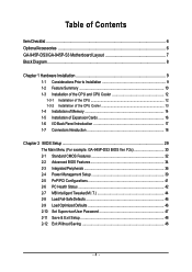
... Health Status 42 2-7 MB Intelligent Tweaker(M.I /O Back Panel Introduction 17 1-7 Connectors Introduction 18 Chapter 2 BIOS Setup 29 The Main Menu (For example: GA-945P-DS3 BIOS Ver. Table of Contents ItemChecklist ...6 OptionalAccessories ...6 GA-945P-DS3/GA-945P-S3 Motherboard Layout 7 Block Diagram ...8 Chapter 1 Hardware Installation 9 1-1 Considerations Prior to Installation 9 1-2 Feature Summary 10 1-3 Installation of the CPU and CPU...
... Health Status 42 2-7 MB Intelligent Tweaker(M.I /O Back Panel Introduction 17 1-7 Connectors Introduction 18 Chapter 2 BIOS Setup 29 The Main Menu (For example: GA-945P-DS3 BIOS Ver. Table of Contents ItemChecklist ...6 OptionalAccessories ...6 GA-945P-DS3/GA-945P-S3 Motherboard Layout 7 Block Diagram ...8 Chapter 1 Hardware Installation 9 1-1 Considerations Prior to Installation 9 1-2 Feature Summary 10 1-3 Installation of the CPU and CPU...
Manual
Page 7
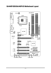
GA-945P-DS3/GA-945P-S3 Motherboard Layout KB_MS ATX_12V LGA775 CPU_FAN COMA LPT GA-945P-DS3/GA-945P-S3 DDRII1 DDRII2 DDRII3 DDRII4 USB USB LAN ATX F_AUDIO AUDIO NB_FAN Intel® 945P RTL8111B CODEC CI IT8718 PCIE_16 PCIE_3 PCIE_1 PCIE_2 PCI1 PCI2 PCI3 CD_IN SPDIF_IO SYS_FAN CLR_CMOS BATTERY Intel® ICH7 PWR_FAN SATAII0 SATAII2 BIOS SATAII1 SATAII3 IDE1 PWR_LED F_PANEL FDD F_USB1 F_USB2 - 7 -
GA-945P-DS3/GA-945P-S3 Motherboard Layout KB_MS ATX_12V LGA775 CPU_FAN COMA LPT GA-945P-DS3/GA-945P-S3 DDRII1 DDRII2 DDRII3 DDRII4 USB USB LAN ATX F_AUDIO AUDIO NB_FAN Intel® 945P RTL8111B CODEC CI IT8718 PCIE_16 PCIE_3 PCIE_1 PCIE_2 PCI1 PCI2 PCI3 CD_IN SPDIF_IO SYS_FAN CLR_CMOS BATTERY Intel® ICH7 PWR_FAN SATAII0 SATAII2 BIOS SATAII1 SATAII3 IDE1 PWR_LED F_PANEL FDD F_USB1 F_USB2 - 7 -
Manual
Page 10
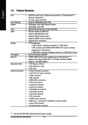
GA-945P-DS3/S3 Motherboard - 10 - English 1-2 Feature Summary CPU Š LGA775 for Intel® CoreTM 2 Extreme dual-core/CoreTM 2 Duo/Pentium® D/ Pentium® 4/Celeron® D Š L2 cache varies with CPU Front Side Bus Š Supports 1066/800/533 MHz FSB Chipset Š Northbridge: Intel® 945P Express Chipset Š Southbridge:... Š 1 S/PDIF In/Out connector Š 2 USB 2.0/1.1 connectors for additional 4 ports by cables Š 1 power LED connector Š 1 Chassis Intrusion connector "*" Only the GA-945P-DS3 adopts All-Solid Capacitor design.
GA-945P-DS3/S3 Motherboard - 10 - English 1-2 Feature Summary CPU Š LGA775 for Intel® CoreTM 2 Extreme dual-core/CoreTM 2 Duo/Pentium® D/ Pentium® 4/Celeron® D Š L2 cache varies with CPU Front Side Bus Š Supports 1066/800/533 MHz FSB Chipset Š Northbridge: Intel® 945P Express Chipset Š Southbridge:... Š 1 S/PDIF In/Out connector Š 2 USB 2.0/1.1 connectors for additional 4 ports by cables Š 1 power LED connector Š 1 Chassis Intrusion connector "*" Only the GA-945P-DS3 adopts All-Solid Capacitor design.
Manual
Page 12
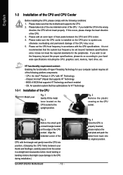
... in the wrong direction, the CPU will not insert properly. Fig. 4 Once the CPU is installed on the CPU socket to the CPU during installation.) GA-945P-DS3/S3 Motherboard - 12 - Please add an even layer of heat paste between your thumb and forefinger, carefully place it enabled - OS: An operation system that...
... in the wrong direction, the CPU will not insert properly. Fig. 4 Once the CPU is installed on the CPU socket to the CPU during installation.) GA-945P-DS3/S3 Motherboard - 12 - Please add an even layer of heat paste between your thumb and forefinger, carefully place it enabled - OS: An operation system that...
Manual
Page 14
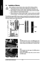
... specifications. Reverse the installation steps when you are designed so that memory of similar capacity, specifications and brand be inserted only in only one direction. GA-945P-DS3/S3 Motherboard - 14 - It is switched off to lock the DIMM module. A memory module can only fit in one direction. Insert the DIMM memory module...
... specifications. Reverse the installation steps when you are designed so that memory of similar capacity, specifications and brand be inserted only in only one direction. GA-945P-DS3/S3 Motherboard - 14 - It is switched off to lock the DIMM module. A memory module can only fit in one direction. Insert the DIMM memory module...
Manual
Page 15
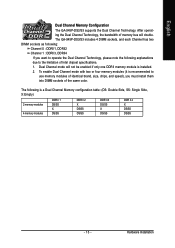
...same color. To enable Dual Channel mode with two or four memory modules (it is installed. 2. English Dual Channel Memory Configuration The GA-945P-DS3/S3 supports the Dual Channel Technology. The following explanations due to operate the Dual Channel Technology, please note the following is a Dual ...DS/SS DDR II 3 DS/SS X DS/SS DDR II 4 X DS/SS DS/SS - 15 - Dual Channel mode will double. Hardware Installation The GA-945P-DS3/S3 includes 4 DIMM sockets, and each Channel has two DIMM sockets as following: Channel 0 : DDRII1, DDRII2 Channel 1 : DDRII3, DDRII4 If you must install...
...same color. To enable Dual Channel mode with two or four memory modules (it is installed. 2. English Dual Channel Memory Configuration The GA-945P-DS3/S3 supports the Dual Channel Technology. The following explanations due to operate the Dual Channel Technology, please note the following is a Dual ...DS/SS DDR II 3 DS/SS X DS/SS DDR II 4 X DS/SS DS/SS - 15 - Dual Channel mode will double. Hardware Installation The GA-945P-DS3/S3 includes 4 DIMM sockets, and each Channel has two DIMM sockets as following: Channel 0 : DDRII1, DDRII2 Channel 1 : DDRII3, DDRII4 If you must install...
Manual
Page 16
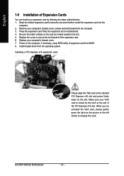
... outlined below: 1. English 1-5 Installation of Expansion Cards You can install your expansion card by the latch at the end of the PCI Express x16 slot. GA-945P-DS3/S3 Motherboard - 16 - Remove your computer's chassis cover. 7. Be sure the metal contacts on the slot. Replace your computer's chassis cover, screws and slot bracket...
... outlined below: 1. English 1-5 Installation of Expansion Cards You can install your expansion card by the latch at the end of the PCI Express x16 slot. GA-945P-DS3/S3 Motherboard - 16 - Remove your computer's chassis cover. 7. Be sure the metal contacts on the slot. Replace your computer's chassis cover, screws and slot bracket...
Manual
Page 18
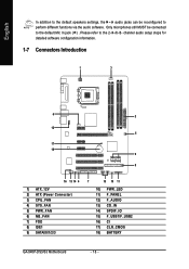
... 7) FDD 8) IDE1 9) SATAII0/1/2/3 7 15 10 11 10) PWR_LED 11) F_PANEL 12) F_AUDIO 13) CD_IN 14) SPDIF_IO 15) F_USB1/F_USB2 16) CI 17) CLR_CMOS 18) BATTERY GA-945P-DS3/S3 Motherboard - 18 - English In addition to the default speakers settings, the ~ audio jacks can be connected to the default Mic In jack ( ) . Please refer...
... 7) FDD 8) IDE1 9) SATAII0/1/2/3 7 15 10 11 10) PWR_LED 11) F_PANEL 12) F_AUDIO 13) CD_IN 14) SPDIF_IO 15) F_USB1/F_USB2 16) CI 17) CLR_CMOS 18) BATTERY GA-945P-DS3/S3 Motherboard - 18 - English In addition to the default speakers settings, the ~ audio jacks can be connected to the default Mic In jack ( ) . Please refer...
Manual
Page 20
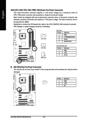
... chip fan will not work if you install it in the wrong direction and sometimes the chip fan will be damaged. Definition 1 GND 1 2 +12V 3 NC GA-945P-DS3/S3 Motherboard - 20 - Most coolers are designed with color-coded power connector wires. Remember to connect the CPU/system fan cable to the CPU_FAN/SYS_FAN...
... chip fan will not work if you install it in the wrong direction and sometimes the chip fan will be damaged. Definition 1 GND 1 2 +12V 3 NC GA-945P-DS3/S3 Motherboard - 20 - Most coolers are designed with color-coded power connector wires. Remember to connect the CPU/system fan cable to the CPU_FAN/SYS_FAN...
Manual
Page 22
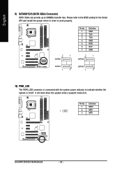
... up to indicate whether the system is on/off. Definition 1 MPD+ 1 2 MPD- 3 MPD- Pin No. It will blink when the system enters suspend mode (S1). GA-945P-DS3/S3 Motherboard - 22 - Please refer to the BIOS setting for the Serial ATA and install the proper driver in order to work properly. 7 1 SATAII0 Pin...
... up to indicate whether the system is on/off. Definition 1 MPD+ 1 2 MPD- 3 MPD- Pin No. It will blink when the system enters suspend mode (S1). GA-945P-DS3/S3 Motherboard - 22 - Please refer to the BIOS setting for the Serial ATA and install the proper driver in order to work properly. 7 1 SATAII0 Pin...
Manual
Page 24
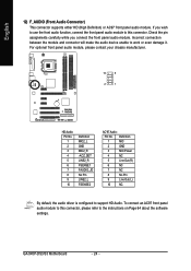
... assignments carefully while you wish to use the front audio function, connect the front panel audio module to this connector, please refer to this connector. GA-945P-DS3/S3 Motherboard - 24 - Definition 1 MIC 2 GND 3 MIC Power 4 NC 5 Line Out (R) 6 NC 7 NC 8 No Pin 9 Line Out (L) 10 NC By default, the audio driver is...
... assignments carefully while you wish to use the front audio function, connect the front panel audio module to this connector, please refer to this connector. GA-945P-DS3/S3 Motherboard - 24 - Definition 1 MIC 2 GND 3 MIC Power 4 NC 5 Line Out (R) 6 NC 7 NC 8 No Pin 9 Line Out (L) 10 NC By default, the audio driver is...
Manual
Page 26
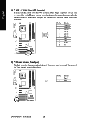
Pin No. Definition 1 Signal 1 2 GND GA-945P-DS3/S3 Motherboard - 26 - For optional front USB cable, please contact your local dealer. 2 10 1 9 Pin No. 1 2 3 4 5 6 7 8 9 10 Definition Power(5V) Power(5V) USB DXUSB DyUSB ...
Pin No. Definition 1 Signal 1 2 GND GA-945P-DS3/S3 Motherboard - 26 - For optional front USB cable, please contact your local dealer. 2 10 1 9 Pin No. 1 2 3 4 5 6 7 8 9 10 Definition Power(5V) Power(5V) USB DXUSB DyUSB ...
Manual
Page 28
English GA-945P-DS3/S3 Motherboard - 28 -
English GA-945P-DS3/S3 Motherboard - 28 -

Manual
Page 30
... POST screen. (To show the BIOS POST screen at system startup, refer to the instructions on the Full Screen LOGO Show item on the screen. GA-945P-DS3/S3 Motherboard - 30 - The Main Menu (For example: GA-945P-DS3 BIOS Ver. This action makes the system reset to the default settings for your motherboard.
... POST screen. (To show the BIOS POST screen at system startup, refer to the instructions on the Full Screen LOGO Show item on the screen. GA-945P-DS3/S3 Motherboard - 30 - The Main Menu (For example: GA-945P-DS3 BIOS Ver. This action makes the system reset to the default settings for your motherboard.
Manual
Page 32
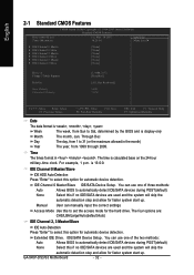
... allow for automatic device detection. IDE Channel 0 Master/Slave IDE/SATA Device Setup. is calculated base on the 24-hour military-time clock. For example, 1 p.m. GA-945P-DS3/S3 Motherboard - 32 - Through Dec The day, from 1999 through 2099.
... allow for automatic device detection. IDE Channel 0 Master/Slave IDE/SATA Device Setup. is calculated base on the 24-hour military-time clock. For example, 1 p.m. GA-945P-DS3/S3 Motherboard - 32 - Through Dec The day, from 1999 through 2099.
Manual
Page 34
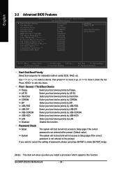
... will not access to exit this function. USB-ZIP Select your boot device priority by USB-ZIP. LAN Select your boot device priority by LAN. GA-945P-DS3/S3 Motherboard - 34 - LS120 Select your boot device priority by LS120. Use < > or < > to select a device, then press to move it down the list. Hard...
... will not access to exit this function. USB-ZIP Select your boot device priority by USB-ZIP. LAN Select your boot device priority by LAN. GA-945P-DS3/S3 Motherboard - 34 - LS120 Select your boot device priority by LS120. Use < > or < > to select a device, then press to move it down the list. Hard...
Manual
Page 36
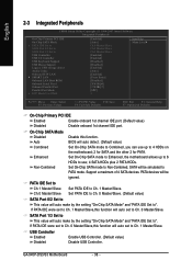
... IDE port. Non-Combined Set On-Chip SATA mode to Ch. 1 Master/Slave. USB Controller Enabled Enable USB Controller. (Default value) Disabled Disable USB Controller. GA-945P-DS3/S3 Motherboard - 36 - BIOS will be ignored. SATA Port 1/3 Set to This value will auto set to ". On-Chip SATA Mode Disabled Auto Disable this...
... IDE port. Non-Combined Set On-Chip SATA mode to Ch. 1 Master/Slave. USB Controller Enabled Enable USB Controller. (Default value) Disabled Disable USB Controller. GA-945P-DS3/S3 Motherboard - 36 - BIOS will be ignored. SATA Port 1/3 Set to This value will auto set to ". On-Chip SATA Mode Disabled Auto Disable this...
Manual
Page 38
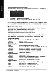
... Port. (Default value) EPP Using Parallel port as ECP & EPP mode. Example: Pair1-2 Status = Short / Length = 1.6m Explanation: A fault or short might occur at Port..... GA-945P-DS3/S3 Motherboard - 38 - it will operate at a speed of 10/100/1000Mbps in MS-DOS mode; Disabled Disable this function. ECP+EPP Using Parallel port...
... Port. (Default value) EPP Using Parallel port as ECP & EPP mode. Example: Pair1-2 Status = Short / Length = 1.6m Explanation: A fault or short might occur at Port..... GA-945P-DS3/S3 Motherboard - 38 - it will operate at a speed of 10/100/1000Mbps in MS-DOS mode; Disabled Disable this function. ECP+EPP Using Parallel port...


