Manual
Page 4
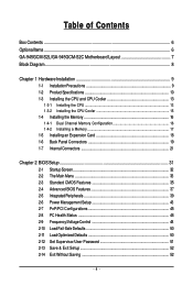
...the CPU Cooler 15 1-4 Installing the Memory 16 1-4-1 Dual Channel Memory Configuration 16 1-4-2 Installing a Memory 17 1-5 Installing an Expansion Card 18 1-6 Back Panel Connectors 19 1-7 Internal Connectors 21 Chapter 2 BIOS Setup 31 2-1 Startup Screen 32 2-2 The Main Menu 33 2-3 Standard CMOS Features 35 2-4 Advanced BIOS Features 37 2-5 IntegratedPeripherals 39 2-6 Power Management Setup 43 2-7 PnP/PCI Configurations 45 2-8 PC Health Status 46 2-9 Frequency/Voltage Control 48 2-10 Load Fail-Safe Defaults 50 2-11 Load Optimized Defaults 50 2-12 Set Supervisor/User Password...
...the CPU Cooler 15 1-4 Installing the Memory 16 1-4-1 Dual Channel Memory Configuration 16 1-4-2 Installing a Memory 17 1-5 Installing an Expansion Card 18 1-6 Back Panel Connectors 19 1-7 Internal Connectors 21 Chapter 2 BIOS Setup 31 2-1 Startup Screen 32 2-2 The Main Menu 33 2-3 Standard CMOS Features 35 2-4 Advanced BIOS Features 37 2-5 IntegratedPeripherals 39 2-6 Power Management Setup 43 2-7 PnP/PCI Configurations 45 2-8 PC Health Status 46 2-9 Frequency/Voltage Control 48 2-10 Load Fail-Safe Defaults 50 2-11 Load Optimized Defaults 50 2-12 Set Supervisor/User Password...
Manual
Page 10
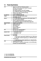
GA-945GCM-S2L/S2C Motherboard - 10 - 1-2 Product Specifications CPU Front Side Bus Chipset Memory Onboard Graphics Audio LAN Expansion Slots Storage Interface USB Š Support for an Intel® CoreTM 2 Extreme processor/ Intel® CoreTM 2 Duo processor/Intel® Pentium® D processor/ Intel® Pentium® 4 processor/ Intel® Celeron® processor in the LGA 775 package (Go to GIGABYTE's website for the latest CPU support list.) Š Support for Intel® Hyper-Threading Technology Š L2 cache varies...
GA-945GCM-S2L/S2C Motherboard - 10 - 1-2 Product Specifications CPU Front Side Bus Chipset Memory Onboard Graphics Audio LAN Expansion Slots Storage Interface USB Š Support for an Intel® CoreTM 2 Extreme processor/ Intel® CoreTM 2 Duo processor/Intel® Pentium® D processor/ Intel® Pentium® 4 processor/ Intel® Celeron® processor in the LGA 775 package (Go to GIGABYTE's website for the latest CPU support list.) Š Support for Intel® Hyper-Threading Technology Š L2 cache varies...
Manual
Page 16
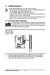
... enabling Dual Channel mode with two memory modules, it is installed. 2. GA-945GCM-S2L/S2C Motherboard - 16 - After the memory is recommended that memory of the same capacity, brand, speed, and chips be used. (Go to GIGABYTE's website for the latest memory support list.) • Always turn off the computer and unplug the power cord from the power outlet before installing the memory to install the memory: • Make sure that memory of the memory. The two DDR2 memory sockets...
... enabling Dual Channel mode with two memory modules, it is installed. 2. GA-945GCM-S2L/S2C Motherboard - 16 - After the memory is recommended that memory of the same capacity, brand, speed, and chips be used. (Go to GIGABYTE's website for the latest memory support list.) • Always turn off the computer and unplug the power cord from the power outlet before installing the memory to install the memory: • Make sure that memory of the memory. The two DDR2 memory sockets...
Manual
Page 18
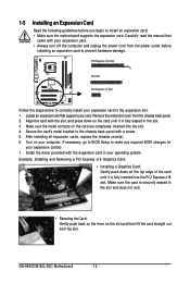
... card straight out from the slot. PCI Express x16 Slot PCI Slot PCI Express x1 Slot Follow the steps below to install an expansion card: • Make sure the motherboard supports the expansion card. After installing all expansion cards, replace the chassis cover(s). 6. Turn on the card are completely inserted into the PCI Express x16 slot. 1-5 Installing an Expansion Card Read the following guidelines before installing an expansion card to make any required BIOS changes for your expansion card(s). 7. Remove the metal slot...
... card straight out from the slot. PCI Express x16 Slot PCI Slot PCI Express x1 Slot Follow the steps below to install an expansion card: • Make sure the motherboard supports the expansion card. After installing all expansion cards, replace the chassis cover(s). 6. Turn on the card are completely inserted into the PCI Express x16 slot. 1-5 Installing an Expansion Card Read the following guidelines before installing an expansion card to make any required BIOS changes for your expansion card(s). 7. Remove the metal slot...
Manual
Page 23
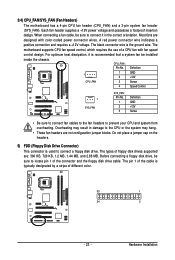
... a fan cable, be sure to connect a floppy disk drive. CPU_FAN : Pin No. The types of a CPU fan with color-coded power connector wires. A red power connector wire indicates a positive connection and requires a +12V voltage. 3/4) CPU_FAN/SYS_FAN (Fan Headers) The motherboard has a 4-pin CPU fan header (CPU_FAN) and a 3-pin system fan header (SYS_FAN). The motherboard supports CPU fan speed control, which requires the use of floppy disk drives supported are: 360 KB, 720 KB, 1.2 MB, 1.44 MB, and 2.88 MB. Hardware Installation Most fans are not configuration jumper...
... a fan cable, be sure to connect a floppy disk drive. CPU_FAN : Pin No. The types of a CPU fan with color-coded power connector wires. A red power connector wire indicates a positive connection and requires a +12V voltage. 3/4) CPU_FAN/SYS_FAN (Fan Headers) The motherboard has a 4-pin CPU fan header (CPU_FAN) and a 3-pin system fan header (SYS_FAN). The motherboard supports CPU fan speed control, which requires the use of floppy disk drives supported are: 360 KB, 720 KB, 1.2 MB, 1.44 MB, and 2.88 MB. Hardware Installation Most fans are not configuration jumper...
Manual
Page 26
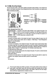
... correctly. HDHD+ Reset Switch IDE Hard Disk Active LED • MSG (Message/Power/Sleep LED): System Status LED Connects to the pin assignments below. A front panel module mainly consists of power switch, reset switch, power LED, hard drive activity LED, speaker and etc. When connecting your system using the power switch (refer to Chapter 2, "BIOS Setup," "Power Management Setup," for information about beep codes. • HD (IDE Hard Drive Activity LED) Connects to this header according to the power status indicator on the chassis front panel. One single short beep will be...
... correctly. HDHD+ Reset Switch IDE Hard Disk Active LED • MSG (Message/Power/Sleep LED): System Status LED Connects to the pin assignments below. A front panel module mainly consists of power switch, reset switch, power LED, hard drive activity LED, speaker and etc. When connecting your system using the power switch (refer to Chapter 2, "BIOS Setup," "Power Management Setup," for information about beep codes. • HD (IDE Hard Drive Activity LED) Connects to this header according to the power status indicator on the chassis front panel. One single short beep will be...
Manual
Page 29
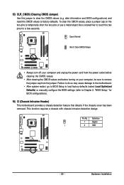
... the chassis cover has been removed. Definition 1 Signal 1 2 GND - 29 - Pin No. 15) CLR_CMOS (Clearing CMOS Jumper) Use this jumper to remove the jumper cap from the jumper. Hardware Installation Failure to do so may cause damage to the motherboard. • After system restart, go to BIOS Setup to load factory defaults (select Load Optimized Defaults) or manually configure the BIOS settings (refer to factory defaults. date information and BIOS configurations) and reset the CMOS values to Chapter 2, "BIOS Setup," for...
... the chassis cover has been removed. Definition 1 Signal 1 2 GND - 29 - Pin No. 15) CLR_CMOS (Clearing CMOS Jumper) Use this jumper to remove the jumper cap from the jumper. Hardware Installation Failure to do so may cause damage to the motherboard. • After system restart, go to BIOS Setup to load factory defaults (select Load Optimized Defaults) or manually configure the BIOS settings (refer to factory defaults. date information and BIOS configurations) and reset the CMOS values to Chapter 2, "BIOS Setup," for...
Manual
Page 31
... the battery/clearing CMOS jumper in Chapter 1 for the beep codes description. • It is a Windows-based utility that searches and downloads the latest version of the BIOS Setup program. To see more advanced BIOS Setup menu options, you can press + in the main menu of BIOS from the Internet and updates the BIOS. To upgrade the BIOS, use either the GIGABYTE Q-Flash or @BIOS utility. • Q-Flash allows the user to quickly and easily upgrade or back up BIOS without entering the...
... the battery/clearing CMOS jumper in Chapter 1 for the beep codes description. • It is a Windows-based utility that searches and downloads the latest version of the BIOS Setup program. To see more advanced BIOS Setup menu options, you can press + in the main menu of BIOS from the Internet and updates the BIOS. To upgrade the BIOS, use either the GIGABYTE Q-Flash or @BIOS utility. • Q-Flash allows the user to quickly and easily upgrade or back up BIOS without entering the...
Manual
Page 34
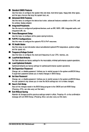
... system/CPU temperature, system voltage and fan speed, etc. „ Frequency/Voltage Control Use this menu to configure the clock and frequency of errors that stop the system boot, etc. „ Advanced BIOS Features Use this menu to configure the device boot order, advanced features available on the CPU, and the primary display adapter. „ Integrated Peripherals Use this menu to configure all peripheral devices, such as IDE, SATA, USB, integrated audio, and integrated LAN, etc. „ Power Management Setup Use this menu to configure all the changes...
... system/CPU temperature, system voltage and fan speed, etc. „ Frequency/Voltage Control Use this menu to configure the clock and frequency of errors that stop the system boot, etc. „ Advanced BIOS Features Use this menu to configure the device boot order, advanced features available on the CPU, and the primary display adapter. „ Integrated Peripherals Use this menu to configure all peripheral devices, such as IDE, SATA, USB, integrated audio, and integrated LAN, etc. „ Power Management Setup Use this menu to configure all the changes...
Manual
Page 35
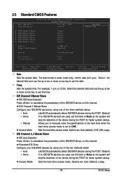
... POST. (Default) If no IDE/SATA devices are used , set this item to set the date. 2-3 Standard CMOS Features Date (mm:dd:yy) Time (hh:mm:ss) CMOS Setup Utility-Copyright (C) 1984-2007 Award Software Standard CMOS Features Mon, Aug 6 2007 10:31:24 Item Help Menu Level` ` IDE Channel 0 Master ` IDE Channel 0 Slave ` IDE Channel 2 Master ` IDE Channel 2 Slave ` IDE Channel 3 Master ` IDE Channel 3 Slave [None] [None] [None] [None] [None] [None] Drive A Floppy 3 Mode Support Halt On [1.44M, 3.5"] [Disabled] [All, But Keyboard] Base Memory...
... POST. (Default) If no IDE/SATA devices are used , set this item to set the date. 2-3 Standard CMOS Features Date (mm:dd:yy) Time (hh:mm:ss) CMOS Setup Utility-Copyright (C) 1984-2007 Award Software Standard CMOS Features Mon, Aug 6 2007 10:31:24 Item Help Menu Level` ` IDE Channel 0 Master ` IDE Channel 0 Slave ` IDE Channel 2 Master ` IDE Channel 2 Slave ` IDE Channel 3 Master ` IDE Channel 3 Slave [None] [None] [None] [None] [None] [None] Drive A Floppy 3 Mode Support Halt On [1.44M, 3.5"] [Disabled] [All, But Keyboard] Base Memory...

Manual
Page 37
... Enter] [Floppy] Item Help Menu Level` Second Boot Device [Hard Disk] Third Boot Device Password Check [CDROM] [Setup] HDD S.M.A.R.T. Use the up or down arrow key to select a device and press to issue warnings when a third party hardware monitor utility is present only if you enter BIOS Setup. Setup System A password is only required for entering the BIOS Setup program. (Default) A password is required for booting the system and for operating systems that support multi-processors mode. (Default: Enabled) (Note) This item is installed. (Default: Disabled) CPU...
... Enter] [Floppy] Item Help Menu Level` Second Boot Device [Hard Disk] Third Boot Device Password Check [CDROM] [Setup] HDD S.M.A.R.T. Use the up or down arrow key to select a device and press to issue warnings when a third party hardware monitor utility is present only if you enter BIOS Setup. Setup System A password is only required for entering the BIOS Setup program. (Default) A password is required for booting the system and for operating systems that support multi-processors mode. (Default: Enabled) (Note) This item is installed. (Default: Disabled) CPU...
Manual
Page 38
... total amount of the monitor display from the PCI Express card and disable the onboard VGA. GA-945GCM-S2L/S2C Motherboard - 38 - set this feature. For more information about Intel CPUs' unique features, please visit Intel's website. When enabled, the CPU core frequency and voltage will be reduced during system halt state to decrease average power consumption and heat production. (Default: Enabled) Virtualization Technology (Note) Enables or disables Intel® Virtualization Technology. With virtualization, one computer system can...
... total amount of the monitor display from the PCI Express card and disable the onboard VGA. GA-945GCM-S2L/S2C Motherboard - 38 - set this feature. For more information about Intel CPUs' unique features, please visit Intel's website. When enabled, the CPU core frequency and voltage will be reduced during system halt state to decrease average power consumption and heat production. (Default: Enabled) Virtualization Technology (Note) Enables or disables Intel® Virtualization Technology. With virtualization, one computer system can...
Manual
Page 39
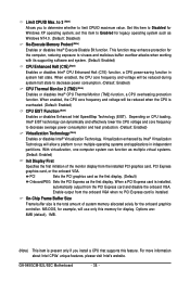
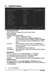
... for GA-945GCM-S2L. - 39 - PATA IDE Set to This item is configurable only if the On-Chip SATA Mode is selected. 2-5 Integrated Peripherals CMOS Setup Utility-Copyright (C) 1984-2007 Award Software Integrated Peripherals On-Chip Primary PCI IDE On-Chip SATA Mode x PATA IDE Set to SATA Port 0/2 Set to SATA Port 1/3 Set to operate in SATA mode. Enhanced Sets all SATA devices to USB Controller USB 2.0 Controller USB Keyboard Support USB Mouse Support Legacy USB storage detect Azalia Codec Onboard H/W LAN ` SMART LAN1 Onboard LAN Boot ROM Onboard Serial Port 1 Onboard Parallel Port...
... for GA-945GCM-S2L. - 39 - PATA IDE Set to This item is configurable only if the On-Chip SATA Mode is selected. 2-5 Integrated Peripherals CMOS Setup Utility-Copyright (C) 1984-2007 Award Software Integrated Peripherals On-Chip Primary PCI IDE On-Chip SATA Mode x PATA IDE Set to SATA Port 0/2 Set to SATA Port 1/3 Set to operate in SATA mode. Enhanced Sets all SATA devices to USB Controller USB 2.0 Controller USB Keyboard Support USB Mouse Support Legacy USB storage detect Azalia Codec Onboard H/W LAN ` SMART LAN1 Onboard LAN Boot ROM Onboard Serial Port 1 Onboard Parallel Port...

Manual
Page 40
...) USB Keyboard Support Allows USB keyboard to be used in MS-DOS. (Default: Disabled) Legacy USB storage detect Determines whether to detect USB storage devices, including USB flash drives and USB hard drives during the POST. (Default: Enabled) Azalia Codec Enables or disables the onboard audio function. (Default: Auto) If you wish to install a 3rd party add-in audio card instead of using the onboard LAN, set this item to Disabled. When PATA IDE Set to is dependent on the On-Chip SATA Mode and PATA IDE Set to Ch. 1 Master/Slave. GA-945GCM-S2L/S2C Motherboard - 40 - USB Controller...
...) USB Keyboard Support Allows USB keyboard to be used in MS-DOS. (Default: Disabled) Legacy USB storage detect Determines whether to detect USB storage devices, including USB flash drives and USB hard drives during the POST. (Default: Enabled) Azalia Codec Enables or disables the onboard audio function. (Default: Auto) If you wish to install a 3rd party add-in audio card instead of using the onboard LAN, set this item to Disabled. When PATA IDE Set to is dependent on the On-Chip SATA Mode and PATA IDE Set to Ch. 1 Master/Slave. GA-945GCM-S2L/S2C Motherboard - 40 - USB Controller...
Manual
Page 42
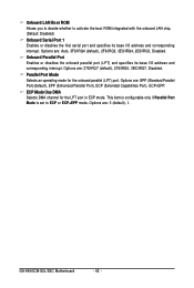
... Port Mode is set to activate the boot ROM integrated with the onboard LAN chip. (Default: Disabled) Onboard Serial Port 1 Enables or disables the first serial port and specifies its base I /O address and corresponding interrupt. Options are : Auto, 3F8/IRQ4 (default), 2F8/IRQ3, 3E8/IRQ4, 2E8/IRQ3, Disabled. ECP Mode Use DMA Selects DMA channel for the onboard parallel (LPT) port. Options are : SPP (Standard Parallel Port)(default), EPP (Enhanced Parallel Port), ECP (Extended Capabilities Port), ECP+EPP. Onboard Parallel Port Enables or disables the onboard...
... Port Mode is set to activate the boot ROM integrated with the onboard LAN chip. (Default: Disabled) Onboard Serial Port 1 Enables or disables the first serial port and specifies its base I /O address and corresponding interrupt. Options are : Auto, 3F8/IRQ4 (default), 2F8/IRQ3, 3E8/IRQ4, 2E8/IRQ3, Disabled. ECP Mode Use DMA Selects DMA channel for the onboard parallel (LPT) port. Options are : SPP (Standard Parallel Port)(default), EPP (Enhanced Parallel Port), ECP (Extended Capabilities Port), ECP+EPP. Onboard Parallel Port Enables or disables the onboard...
Manual
Page 48
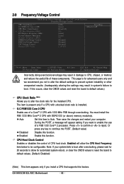
...: Fail-Safe Defaults ESC: Exit F1: General Help F7: Optimized Defaults Incorrectly doing overclock/overvoltage may result in damage to CPU, chipset, or memory and reduce the useful life of a CoreTM 2 CPU with DDR2 533 (or above) memory module(s). This page is installed. GA-945GCM-S2L/S2C Motherboard - 48 - Or press any key to continue the POST. (Default value) Disabled Disable this occurs, clear the CMOS values and reset the board to default values.) CPU Clock Ratio...
...: Fail-Safe Defaults ESC: Exit F1: General Help F7: Optimized Defaults Incorrectly doing overclock/overvoltage may result in damage to CPU, chipset, or memory and reduce the useful life of a CoreTM 2 CPU with DDR2 533 (or above) memory module(s). This page is installed. GA-945GCM-S2L/S2C Motherboard - 48 - Or press any key to continue the POST. (Default value) Disabled Disable this occurs, clear the CMOS values and reset the board to default values.) CPU Clock Ratio...
Manual
Page 52
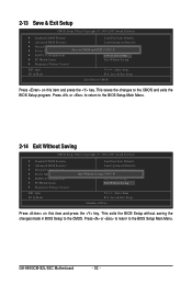
... Award Software ` Standard CMOS Features ` Advanced BIOS Features ` Integrated Peripherals ` Power Management Setup ` PnP/PCI Configurations ` PC Health Status ` Frequency/Voltage Control ESC: Quit F8: Q-Flash Load Fail-Safe Defaults Load Optimized Defaults Set Supervisor Password Quit Without Saving (SYe/tNU)?seNr Password Save & Exit Setup Exit Without Saving KLJI: Select Item F10: Save & Exit Setup Abandon all Data Press on this item and press the key. Press or to return to the CMOS. GA-945GCM-S2L...
... Award Software ` Standard CMOS Features ` Advanced BIOS Features ` Integrated Peripherals ` Power Management Setup ` PnP/PCI Configurations ` PC Health Status ` Frequency/Voltage Control ESC: Quit F8: Q-Flash Load Fail-Safe Defaults Load Optimized Defaults Set Supervisor Password Quit Without Saving (SYe/tNU)?seNr Password Save & Exit Setup Exit Without Saving KLJI: Select Item F10: Save & Exit Setup Abandon all Data Press on this item and press the key. Press or to return to the CMOS. GA-945GCM-S2L...

Manual
Page 53
... and then list all the driver items. • Please ignore the popup dialog box(es) (e.g. Drivers Installation Failure to install other applications included in the motherboard driver disk. • For USB 2.0 driver support under the Windows XP operating system, please install the Windows XP Service Pack 1 or later. The driver Autorun screen is installing the drivers. You can press Xpress Install to install all the drivers that shown in Device Manager, please remove the question...
... and then list all the driver items. • Please ignore the popup dialog box(es) (e.g. Drivers Installation Failure to install other applications included in the motherboard driver disk. • For USB 2.0 driver support under the Windows XP operating system, please install the Windows XP Service Pack 1 or later. The driver Autorun screen is installing the drivers. You can press Xpress Install to install all the drivers that shown in Device Manager, please remove the question...
Manual
Page 63
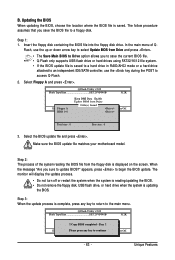
... a hard drive in RAID/AHCI mode or a hard drive attached to an independent IDE/SATA controller, use the up or down arrow key to select Update BIOS from Drive and press . • The Save Main BIOS to Drive option allows you to save the BIOS file to access Q-Flash. 2. Step 2: The process of Q- CopUypBdIaOteSBcIoOmSpflerotemd -DPriavses !! The follow procedure assumes that you sure to begin the BIOS update. Q-Flash Utility v2.02 Flash Type/Size SST 25VF040B 512K EnteFr l:oRppuyn A HDD 0-0 Keep...
... a hard drive in RAID/AHCI mode or a hard drive attached to an independent IDE/SATA controller, use the up or down arrow key to select Update BIOS from Drive and press . • The Save Main BIOS to Drive option allows you to save the BIOS file to access Q-Flash. 2. Step 2: The process of Q- CopUypBdIaOteSBcIoOmSpflerotemd -DPriavses !! The follow procedure assumes that you sure to begin the BIOS update. Q-Flash Utility v2.02 Flash Type/Size SST 25VF040B 512K EnteFr l:oRppuyn A HDD 0-0 Keep...
Manual
Page 77
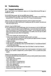
...jumper to the Support\Motherboard\FAQ page on the motherboard battery in the BIOS Setup program. Press to show the advanced options. Appendix A: Some advanced options are some BIOS options missing? A: If your computer. A: The following Award BIOS beep code descriptions may help you identify possible computer problems. (For reference only.) 1 short: System boots successfully 2 short: CMOS setting error 1 long, 1 short: Memory or motherboard error 1 long, 2 short: Monitor or graphics card error 1 long, 3 short: Keyboard error 1 long, 9 short: BIOS ROM error Continuous long beeps...
...jumper to the Support\Motherboard\FAQ page on the motherboard battery in the BIOS Setup program. Press to show the advanced options. Appendix A: Some advanced options are some BIOS options missing? A: If your computer. A: The following Award BIOS beep code descriptions may help you identify possible computer problems. (For reference only.) 1 short: System boots successfully 2 short: CMOS setting error 1 long, 1 short: Memory or motherboard error 1 long, 2 short: Monitor or graphics card error 1 long, 3 short: Keyboard error 1 long, 9 short: BIOS ROM error Continuous long beeps...


