Manual
Page 4
Table of Contents Box Contents ...6 OptionalItems...6 GA-945GCM-S2L/GA-945GCM-S2C Motherboard Layout 7 Block Diagram...8 Chapter 1 Hardware Installation 9 1-1 Installation Precautions 9 1-2 Product Specifications 10 1-3 Installing the CPU and CPU Cooler 13 1-3-1 Installing the CPU 13 1-3-2 Installing the CPU Cooler 15 1-4 Installing the Memory 16 1-4-1 Dual Channel Memory Configuration 16 1-4-2 Installing a Memory 17 1-5 Installing an Expansion Card 18 1-6 Back Panel Connectors...
Table of Contents Box Contents ...6 OptionalItems...6 GA-945GCM-S2L/GA-945GCM-S2C Motherboard Layout 7 Block Diagram...8 Chapter 1 Hardware Installation 9 1-1 Installation Precautions 9 1-2 Product Specifications 10 1-3 Installing the CPU and CPU Cooler 13 1-3-1 Installing the CPU 13 1-3-2 Installing the CPU Cooler 15 1-4 Installing the Memory 16 1-4-1 Dual Channel Memory Configuration 16 1-4-2 Installing a Memory 17 1-5 Installing an Expansion Card 18 1-6 Back Panel Connectors...
Manual
Page 8
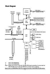
...) D-Sub PCI Express x16 1 PCI Express x1 LAN RJ45 PCIe CLK (100 MHz) x1 RTL8111C RTL8101E PCI Express Bus PCI Bus LGA775 Processor CPU CLK+/(333(Note 1)/266/200/133 MHz) Host Interface Intel® 945GC DDR2 667/533/400 MHz(Note 2) Dual Channel Memory GMCH CLK (333...for GA-945GCM-S2C. (Note 1) Enable use of a 1066/800 MHz FSB CPU is required if you wish to install DDR2 667 MHz memory. - 8 - You must install the FSB 1333 MHz CoreTM 2 CPU with DDR2 533 (or above) memory module(s). (Note 2) Use of a CoreTM 2 CPU with 1333 MHz FSB through overclocking. Only for GA-945GCM-S2L.
...) D-Sub PCI Express x16 1 PCI Express x1 LAN RJ45 PCIe CLK (100 MHz) x1 RTL8111C RTL8101E PCI Express Bus PCI Bus LGA775 Processor CPU CLK+/(333(Note 1)/266/200/133 MHz) Host Interface Intel® 945GC DDR2 667/533/400 MHz(Note 2) Dual Channel Memory GMCH CLK (333...for GA-945GCM-S2C. (Note 1) Enable use of a 1066/800 MHz FSB CPU is required if you wish to install DDR2 667 MHz memory. - 8 - You must install the FSB 1333 MHz CoreTM 2 CPU with DDR2 533 (or above) memory module(s). (Note 2) Use of a CoreTM 2 CPU with 1333 MHz FSB through overclocking. Only for GA-945GCM-S2L.
Manual
Page 9
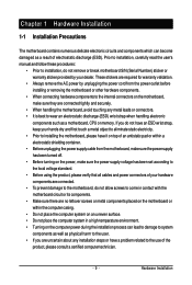
..., do not allow screws to come in a high-temperature environment. • Turning on the computer power during the installation process can become damaged as a motherboard, CPU or memory. If you are connected tightly and securely. • When handling the motherboard, avoid touching any installation steps or have a problem related to the...
..., do not allow screws to come in a high-temperature environment. • Turning on the computer power during the installation process can become damaged as a motherboard, CPU or memory. If you are connected tightly and securely. • When handling the motherboard, avoid touching any installation steps or have a problem related to the...
Manual
Page 10
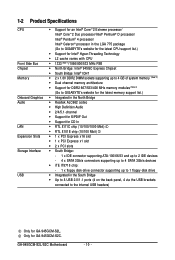
GA-945GCM-S2L/S2C Motherboard - 10 - 1-2 Product Specifications CPU Front Side Bus Chipset Memory Onboard Graphics Audio LAN Expansion Slots Storage Interface USB Š Support for an Intel® CoreTM 2 Extreme processor/ Intel® ... up to 4 GB of system memory (Note 2) Š Dual channel memory architecture Š Support for DDR2 667/533/400 MHz memory modules (Note 3) (Go to GIGABYTE's website for the latest memory support list.) Š Integrated in the North Bridge Š Realtek ALC662 codec Š High Definition Audio Š 2/4/5.1-channel Š Support...
GA-945GCM-S2L/S2C Motherboard - 10 - 1-2 Product Specifications CPU Front Side Bus Chipset Memory Onboard Graphics Audio LAN Expansion Slots Storage Interface USB Š Support for an Intel® CoreTM 2 Extreme processor/ Intel® ... up to 4 GB of system memory (Note 2) Š Dual channel memory architecture Š Support for DDR2 667/533/400 MHz memory modules (Note 3) (Go to GIGABYTE's website for the latest memory support list.) Š Integrated in the North Bridge Š Realtek ALC662 codec Š High Definition Audio Š 2/4/5.1-channel Š Support...
Manual
Page 11
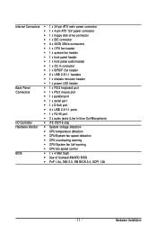
...Š 1 x 4-pin ATX 12V power connector Š 1 x floppy disk drive connector Š 1 x IDE connector Š 4 x SATA 3Gb/s connectors Š 1 x CPU fan header Š 1 x system fan header Š 1 x front panel header Š 1 x front panel audio header Š 1 x CD In connector Š 1 x... Š iTE IT8718 chip Hardware Monitor Š System voltage detection Š CPU temperature detection Š CPU/System fan speed detection Š CPU overheating warning Š CPU/System fan fail warning Š CPU fan speed control BIOS Š 1 x 4 Mbit flash Š Use ...
...Š 1 x 4-pin ATX 12V power connector Š 1 x floppy disk drive connector Š 1 x IDE connector Š 4 x SATA 3Gb/s connectors Š 1 x CPU fan header Š 1 x system fan header Š 1 x front panel header Š 1 x front panel audio header Š 1 x CD In connector Š 1 x... Š iTE IT8718 chip Hardware Monitor Š System voltage detection Š CPU temperature detection Š CPU/System fan speed detection Š CPU overheating warning Š CPU/System fan fail warning Š CPU fan speed control BIOS Š 1 x 4 Mbit flash Š Use ...
Manual
Page 12
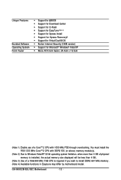
GA-945GCM-S2L/S2C Motherboard - 12 - You must install the FSB 1333 MHz CoreTM 2 CPU with 1333 MHz FSB through overclocking. Unique Features Bundled Software Operating System Form Factor Š Support for @BIOS Š Support for Download Center Š Support ... (OEM version) Š Support for Microsoft® Windows® Vista/XP Š Micro ATX form factor; 24.4cm x 19.3cm (Note 1) Enable use of a CoreTM 2 CPU with DDR2 533 (or above) memory module(s). (Note 2) Due to Windows Vista/XP 32-bit operating system limitation, when more than 4 GB of physical memory...
GA-945GCM-S2L/S2C Motherboard - 12 - You must install the FSB 1333 MHz CoreTM 2 CPU with 1333 MHz FSB through overclocking. Unique Features Bundled Software Operating System Form Factor Š Support for @BIOS Š Support for Download Center Š Support ... (OEM version) Š Support for Microsoft® Windows® Vista/XP Š Micro ATX form factor; 24.4cm x 19.3cm (Note 1) Enable use of a CoreTM 2 CPU with DDR2 533 (or above) memory module(s). (Note 2) Due to Windows Vista/XP 32-bit operating system limitation, when more than 4 GB of physical memory...
Manual
Page 13
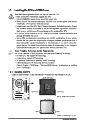
... before you begin to install the CPU: • Make sure that the motherboard supports the CPU. (Go to GIGABYTE's website for the latest CPU support list.) • Always turn off the computer and unplug the power cord from the power outlet before installing the CPU to prevent hardware damage. •... Locate the pin one of the CPU may locate the notches...
... before you begin to install the CPU: • Make sure that the motherboard supports the CPU. (Go to GIGABYTE's website for the latest CPU support list.) • Always turn off the computer and unplug the power cord from the power outlet before installing the CPU to prevent hardware damage. •... Locate the pin one of the CPU may locate the notches...
Manual
Page 14
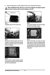
Step 5: Once the CPU is not installed.) Step 4: Hold the CPU with the socket alignment keys) and gently insert the CPU into the motherboard CPU socket. Align the CPU pin one marking (triangle) with the pin one corner of the CPU socket (or you may align the CPU notches with your thumb and index fingers. GA-945GCM-S2L/S2C Motherboard - 14...
Step 5: Once the CPU is not installed.) Step 4: Hold the CPU with the socket alignment keys) and gently insert the CPU into the motherboard CPU socket. Align the CPU pin one marking (triangle) with the pin one corner of the CPU socket (or you may align the CPU notches with your thumb and index fingers. GA-945GCM-S2L/S2C Motherboard - 14...
Manual
Page 15
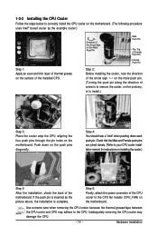
.... If the push pin is inserted as the example cooler.) Step 1: Apply an even and thin layer of thermal grease on the surface of the CPU cooler to the CPU fan header (CPU_FAN) on the motherboard. Check that the Male and Female push pins are joined closely. (Refer to your... 5: After the installation, check the back of arrow is to remove the cooler, on the contrary, is to install.) Step 3: Place the cooler atop the CPU, aligning the four push pins through the pin holes on the motherboard. Hardware Installation Step 6: Finally, attach the power connector of the installed...
.... If the push pin is inserted as the example cooler.) Step 1: Apply an even and thin layer of thermal grease on the surface of the CPU cooler to the CPU fan header (CPU_FAN) on the motherboard. Check that the Male and Female push pins are joined closely. (Refer to your... 5: After the installation, check the back of arrow is to remove the cooler, on the contrary, is to install.) Step 3: Place the cooler atop the CPU, aligning the four push pins through the pin holes on the motherboard. Hardware Installation Step 6: Finally, attach the power connector of the installed...
Manual
Page 22
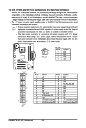
... cover when using a 2x12 power supply, remove the protective cover from the main power connector on the motherboard. Connect the power supply cable to the CPU. If a power supply is compatible with power supplies with 2x10 power connectors. If the 12V power connector is not connected, the computer will not start... Definition 3.3V -12V GND PS_ON(soft On/Off) GND GND GND -5V +5V +5V +5V (Only for 2x12-pinATX) GND (Only for 2x12-pin ATX) GA-945GCM-S2L/S2C Motherboard - 22 -
... cover when using a 2x12 power supply, remove the protective cover from the main power connector on the motherboard. Connect the power supply cable to the CPU. If a power supply is compatible with power supplies with 2x10 power connectors. If the 12V power connector is not connected, the computer will not start... Definition 3.3V -12V GND PS_ON(soft On/Off) GND GND GND -5V +5V +5V +5V (Only for 2x12-pinATX) GND (Only for 2x12-pin ATX) GA-945GCM-S2L/S2C Motherboard - 22 -
Manual
Page 23
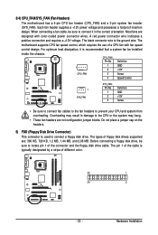
...connect it is typically designated by a stripe of the connector and the floppy disk drive cable. The black connector wire is used to the CPU or the system may hang. • These fan headers are designed with fan speed control design. For optimum heat dissipation, it in ... with color-coded power connector wires. 3/4) CPU_FAN/SYS_FAN (Fan Headers) The motherboard has a 4-pin CPU fan header (CPU_FAN) and a 3-pin system fan header (SYS_FAN). The motherboard supports CPU fan speed control, which requires the use of floppy disk drives supported are: 360 KB, 720 KB, 1.2 MB, 1.44 MB, ...
...connect it is typically designated by a stripe of the connector and the floppy disk drive cable. The black connector wire is used to the CPU or the system may hang. • These fan headers are designed with fan speed control design. For optimum heat dissipation, it in ... with color-coded power connector wires. 3/4) CPU_FAN/SYS_FAN (Fan Headers) The motherboard has a 4-pin CPU fan header (CPU_FAN) and a 3-pin system fan header (SYS_FAN). The motherboard supports CPU fan speed control, which requires the use of floppy disk drives supported are: 360 KB, 720 KB, 1.2 MB, 1.44 MB, ...
Manual
Page 34
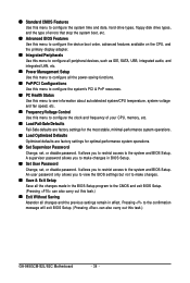
...errors that stop the system boot, etc. „ Advanced BIOS Features Use this menu to configure the device boot order, advanced features available on the CPU, and the primary display adapter. „ Integrated Peripherals Use this menu to configure all peripheral devices, such as IDE, SATA, USB, integrated audio,... Use this menu to configure the system's PCI & PnP resources. „ PC Health Status Use this menu to see information about autodetected system/CPU temperature, system voltage and fan speed, etc. „ Frequency/Voltage Control Use this task.) GA-945GCM-S2L/S2C Motherboard - 34 -
...errors that stop the system boot, etc. „ Advanced BIOS Features Use this menu to configure the device boot order, advanced features available on the CPU, and the primary display adapter. „ Integrated Peripherals Use this menu to configure all peripheral devices, such as IDE, SATA, USB, integrated audio,... Use this menu to configure the system's PCI & PnP resources. „ PC Health Status Use this menu to see information about autodetected system/CPU temperature, system voltage and fan speed, etc. „ Frequency/Voltage Control Use this task.) GA-945GCM-S2L/S2C Motherboard - 34 -

Manual
Page 37
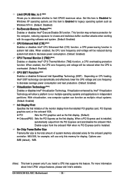
... Disk] Third Boot Device Password Check [CDROM] [Setup] HDD S.M.A.R.T. to 3 (Note) No-Execute Memory Protect (Note) CPU Enhanced Halt (C1E) (Note) CPU Thermal Monitor 2(TM2) (Note) CPU EIST Function (Note) Virtualization Technology (Note) [Disabled] [Enabled] [Disabled] [Enabled] [Enabled] [Enabled] [Enabled] [Enabled...is required for booting the system and for entering the BIOS Setup program. (Default) A password is installed. (Default: Disabled) CPU Hyper-Threading (Note) Enables or disables Intel® Hyper-Threading Technology. Options are: Floppy, LS120, Hard Disk, CDROM, ZIP,...
... Disk] Third Boot Device Password Check [CDROM] [Setup] HDD S.M.A.R.T. to 3 (Note) No-Execute Memory Protect (Note) CPU Enhanced Halt (C1E) (Note) CPU Thermal Monitor 2(TM2) (Note) CPU EIST Function (Note) Virtualization Technology (Note) [Disabled] [Enabled] [Disabled] [Enabled] [Enabled] [Enabled] [Enabled] [Enabled...is required for booting the system and for entering the BIOS Setup program. (Default) A password is installed. (Default: Disabled) CPU Hyper-Threading (Note) Enables or disables Intel® Hyper-Threading Technology. Options are: Floppy, LS120, Hard Disk, CDROM, ZIP,...
Manual
Page 38
...Note) Enables or disables Intel® Virtualization Technology. On-Chip Frame Buffer Size Frame buffer size is overheated. (Default: Enabled) CPU EIST Function (Note) Enables or disables Enhanced Intel SpeedStep Technology (EIST). For more information about Intel CPUs' unique features, please ... Express as the first display. Depending on CPU loading, Intel® EIST technology can function as Windows NT4.0. (Default: Disabled) No-Execute Memory Protect (Note) Enables or disables Intel® Execute Disable Bit function. GA-945GCM-S2L/S2C Motherboard - 38 - MS-DOS,...
...Note) Enables or disables Intel® Virtualization Technology. On-Chip Frame Buffer Size Frame buffer size is overheated. (Default: Enabled) CPU EIST Function (Note) Enables or disables Enhanced Intel SpeedStep Technology (EIST). For more information about Intel CPUs' unique features, please ... Express as the first display. Depending on CPU loading, Intel® EIST technology can function as Windows NT4.0. (Default: Disabled) No-Execute Memory Protect (Note) Enables or disables Intel® Execute Disable Bit function. GA-945GCM-S2L/S2C Motherboard - 38 - MS-DOS,...
Manual
Page 46
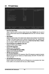
..., 90oC/194oF. Current CPU Temperature Displays current CPU temperature. Current CPU/SYSTEM FAN Speed (RPM) Displays current CPU/system fan speed. When CPU temperature exceeds the threshold, BIOS will show "No". CPU/SYSTEM FAN Fail Warning Allows the system to emit warning sound if the CPU/system fan is removed, this occurs. (Default: Disabled) GA-945GCM-S2L/S2C Motherboard - 46...
..., 90oC/194oF. Current CPU Temperature Displays current CPU temperature. Current CPU/SYSTEM FAN Speed (RPM) Displays current CPU/system fan speed. When CPU temperature exceeds the threshold, BIOS will show "No". CPU/SYSTEM FAN Fail Warning Allows the system to emit warning sound if the CPU/system fan is removed, this occurs. (Default: Disabled) GA-945GCM-S2L/S2C Motherboard - 46...
Manual
Page 47
If disabled, CPU fan runs at different speed according to the CPU temperature. CPU Smart FAN Control Enables or disables the CPU fan speed control function. Enabled allows the CPU fan to run at full speed. (Default: Enabled) - 47 - BIOS Setup You can adjust the fan speed with EasyTune based on system requirements.
If disabled, CPU fan runs at different speed according to the CPU temperature. CPU Smart FAN Control Enables or disables the CPU fan speed control function. Enabled allows the CPU fan to run at full speed. (Default: Enabled) - 47 - BIOS Setup You can adjust the fan speed with EasyTune based on system requirements.
Manual
Page 48
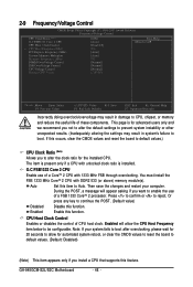
...computer. 2-9 Frequency/Voltage Control CMOS Setup Utility-Copyright (C) 1984-2007 Award Software Frequency/Voltage Control CPU Clock Ratio (Note) O.C FSB1333 Core. 2 CPU CPU Host Clock Control x CPU Host Frequency(Mhz) PCI Express Frequency (Mhz) System Memory Multiplier Memory Frequency (Mhz) DIMM ...CPU host clock. The item is present only if a CPU with unlocked clock ratio is for the installed CPU. Then save the changes and restart your system fails to boot after overclocking, please wait for 20 seconds to allow the CPU Host Frequency item below to be configurable. GA-945GCM-S2L...
...computer. 2-9 Frequency/Voltage Control CMOS Setup Utility-Copyright (C) 1984-2007 Award Software Frequency/Voltage Control CPU Clock Ratio (Note) O.C FSB1333 Core. 2 CPU CPU Host Clock Control x CPU Host Frequency(Mhz) PCI Express Frequency (Mhz) System Memory Multiplier Memory Frequency (Mhz) DIMM ...CPU host clock. The item is present only if a CPU with unlocked clock ratio is for the installed CPU. Then save the changes and restart your system fails to boot after overclocking, please wait for 20 seconds to allow the CPU Host Frequency item below to be configurable. GA-945GCM-S2L...
Manual
Page 49
... data. (Default: Auto) Memory Frequency (Mhz) The memory frequency value is enabled. The adjustable range is highly recommended that the CPU frequency be set this item to set memory voltage. Normal Supplies the memory voltage as required. FSB OverVoltage Control Allows you to 266... MHz. Normal sets the CPU voltage as required. (Default) +0.1V ~ +0.4V Increases memory voltage by 0.1V to 200 MHz. Auto sets the PCIe clock frequency ...
... data. (Default: Auto) Memory Frequency (Mhz) The memory frequency value is enabled. The adjustable range is highly recommended that the CPU frequency be set this item to set memory voltage. Normal Supplies the memory voltage as required. FSB OverVoltage Control Allows you to 266... MHz. Normal sets the CPU voltage as required. (Default) +0.1V ~ +0.4V Increases memory voltage by 0.1V to 200 MHz. Auto sets the PCIe clock frequency ...
Manual
Page 67
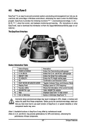
...the PC Health setting page Confirmation and Execution button Toggles between Easy and Advance Mode Displays panel of CPU frequency Shows the information of the current function Visits GIGABYTE website Displays EasyTuneTM 5 help screen Quits or minimizes EasyTuneTM 5 Incorrectly doing overclock/overvoltage may result in ... other unexpected results may occur. (Note 1) Available functions in EasyTune 5 may differ by motherboard model. (Note 2) C.I.A. Display Field 8. GIGABYTE Logo 10. Before you do the overclock/overvoltage, make sure that you do overclock and overvoltage in damage to...
...the PC Health setting page Confirmation and Execution button Toggles between Easy and Advance Mode Displays panel of CPU frequency Shows the information of the current function Visits GIGABYTE website Displays EasyTuneTM 5 help screen Quits or minimizes EasyTuneTM 5 Incorrectly doing overclock/overvoltage may result in ... other unexpected results may occur. (Note 1) Available functions in EasyTune 5 may differ by motherboard model. (Note 2) C.I.A. Display Field 8. GIGABYTE Logo 10. Before you do the overclock/overvoltage, make sure that you do overclock and overvoltage in damage to...

Manual
Page 78
...power cable. Yes Isolate the short circuit. Is the power connector of the CPU cooler connected to enter BIOS Setup. Yes Insert the graphics card. Press to the CPU_FAN header properly? A (Continued...) GA-945GCM-S2L/S2C Motherboard - 78 - START Turn off the power. The problem is ...the motherboard does not short-circuit with the chassis or other metal objects. Turn on the memory slot. Secure the CPU No cooler on the CPU. No Correctly insert the memory into the memory socket. 5-2-2 Troubleshooting Procedure If you encounter any troubles during system startup...
...power cable. Yes Isolate the short circuit. Is the power connector of the CPU cooler connected to enter BIOS Setup. Yes Insert the graphics card. Press to the CPU_FAN header properly? A (Continued...) GA-945GCM-S2L/S2C Motherboard - 78 - START Turn off the power. The problem is ...the motherboard does not short-circuit with the chassis or other metal objects. Turn on the memory slot. Secure the CPU No cooler on the CPU. No Correctly insert the memory into the memory socket. 5-2-2 Troubleshooting Procedure If you encounter any troubles during system startup...


