Manual
Page 9
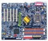
... Summary CPU Motherboard Chipset Memory Slots On-Board IDE On-Board Floppy On-Board Peripherals y Supports the latest Intel® Pentium® 4 Socket 775 CPU y Supports 533/800MHz FSB y L2 cache varies with CPU y GA-8IPE775 Series Motherboard: GA-8IPE775 Pro/GA-8IPE775-G/GA-8IPE775 y North Bridge: Intel® 865PE y South Bridge: Intel® ICH5 y 4 184-pin DDR DIMM sockets y Supports Dual channel DDR400/DDR333/DDR266 DIMM y Supports 128MB/256MB/512MB/1GB unbuffered DRAM y Supports up to 4GB DRAM (Max) (Note 1) y 1 AGP slot supports 8X/4X(1.5V) mode y 5 PCI slots y 2 IDE bus master...
... Summary CPU Motherboard Chipset Memory Slots On-Board IDE On-Board Floppy On-Board Peripherals y Supports the latest Intel® Pentium® 4 Socket 775 CPU y Supports 533/800MHz FSB y L2 cache varies with CPU y GA-8IPE775 Series Motherboard: GA-8IPE775 Pro/GA-8IPE775-G/GA-8IPE775 y North Bridge: Intel® 865PE y South Bridge: Intel® ICH5 y 4 184-pin DDR DIMM sockets y Supports Dual channel DDR400/DDR333/DDR266 DIMM y Supports 128MB/256MB/512MB/1GB unbuffered DRAM y Supports up to 4GB DRAM (Max) (Note 1) y 1 AGP slot supports 8X/4X(1.5V) mode y 5 PCI slots y 2 IDE bus master...
Manual
Page 10
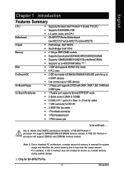
...-Board LAN On-Board IEEE1394 On-Board Sound Serial ATA Hardware Monitor I/O Control PS/2 Connector BIOS Additional Features Overclocking Form Factor y Build in Marvell 8001 Chipset (10/100/1000 Mbit) y 1 RJ45 port y Ti TSB43AB23 y ALC850 CODEC (UAJ) y Supports Jack Sensing function y Supports 2 / 4 / 6 / 8 channel audio y Supports Line In / Line Out / MIC connection y Surround Back Speaker (use of Surround-Kit to select) y SPDIF In / Out y CD In / Game connector y 2 Serial ATA connectors (SATA0/SATA1) y Controlled by ICH5 y CPU/Power /System Fan...
...-Board LAN On-Board IEEE1394 On-Board Sound Serial ATA Hardware Monitor I/O Control PS/2 Connector BIOS Additional Features Overclocking Form Factor y Build in Marvell 8001 Chipset (10/100/1000 Mbit) y 1 RJ45 port y Ti TSB43AB23 y ALC850 CODEC (UAJ) y Supports Jack Sensing function y Supports 2 / 4 / 6 / 8 channel audio y Supports Line In / Line Out / MIC connection y Surround Back Speaker (use of Surround-Kit to select) y SPDIF In / Out y CD In / Game connector y 2 Serial ATA connectors (SATA0/SATA1) y Controlled by ICH5 y CPU/Power /System Fan...
Manual
Page 15
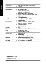
Install I/O Peripherals Cables Step 4 Step 1 Step 2 Step 4 Step 4 Step 3 Congratulations! Continue with the BIOS/software installation. - 11 - Install the Central Processing Unit (CPU) Step 2- You have accomplished the hardware installation! Install expansion cards Step 4- Turn on the power supply or connect the power cable to the power outlet. Install memory modules Step 3- English Chapter 2 Hardware Installation Process To set up your computer, you must complete the following steps: Step 1- Hardware Installation Process
Install I/O Peripherals Cables Step 4 Step 1 Step 2 Step 4 Step 4 Step 3 Congratulations! Continue with the BIOS/software installation. - 11 - Install the Central Processing Unit (CPU) Step 2- You have accomplished the hardware installation! Install expansion cards Step 4- Turn on the power supply or connect the power cable to the power outlet. Install memory modules Step 3- English Chapter 2 Hardware Installation Process To set up your computer, you must complete the following steps: Step 1- Hardware Installation Process
Manual
Page 17
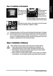
... the user manual) Fig. 3 Please attach the power connector of the heatsink to prevent hardware damage. 3. A memory module can be installed in damage to the CPU as a result of hardening of the heatsink paste. Memory modules have a foolproof insertion design. The heatsink may become pulled from its locked position and result in only one direction. If the heatsink is switched off to the CPU fan header located...
... the user manual) Fig. 3 Please attach the power connector of the heatsink to prevent hardware damage. 3. A memory module can be installed in damage to the CPU as a result of hardening of the heatsink paste. Memory modules have a foolproof insertion design. The heatsink may become pulled from its locked position and result in only one direction. If the heatsink is switched off to the CPU fan header located...
Manual
Page 22
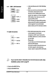
... In jack. Only for GA-8IPE775 Pro. Devices like CD-ROM, walkman etc. GA-8IPE775 Series Motherboard - 18 - Before you may connect speaker to Line Out jack, microphone to Line-In jack. English / USB / LAN Connector USB 0 USB 1 LAN USB 2 USB 3 Audio Connectors Line In Line Out MIC In LAN is fast Ethernet with 10/100/1000 Mbps speed. If your OS does not support USB controller, please contact OS vendor for 2-/4-/6-/8-channel audio setup installation, please refer to page...
... In jack. Only for GA-8IPE775 Pro. Devices like CD-ROM, walkman etc. GA-8IPE775 Series Motherboard - 18 - Before you may connect speaker to Line Out jack, microphone to Line-In jack. English / USB / LAN Connector USB 0 USB 1 LAN USB 2 USB 3 Audio Connectors Line In Line Out MIC In LAN is fast Ethernet with 10/100/1000 Mbps speed. If your OS does not support USB controller, please contact OS vendor for 2-/4-/6-/8-channel audio setup installation, please refer to page...
Manual
Page 35
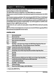
... user to quickly and easily update or backup BIOS without entering the operating system. @BIOS is a Windows-based utility that you wish to upgrade to a new BIOS, either Gigabyte's Q-Flash or @BIOS utility can enter the BIOS setup screen by pressing "Ctrl + F1". The CMOS SETUP saves the configuration in the right hand Select item Main Menu - You can be reset to the item in the CMOS SRAM of the motherboard. When setting up BIOS for GA-8IPE775 Pro. - 31 - BIOS Setup...
... user to quickly and easily update or backup BIOS without entering the operating system. @BIOS is a Windows-based utility that you wish to upgrade to a new BIOS, either Gigabyte's Q-Flash or @BIOS utility can enter the BIOS setup screen by pressing "Ctrl + F1". The CMOS SETUP saves the configuration in the right hand Select item Main Menu - You can be reset to the item in the CMOS SRAM of the motherboard. When setting up BIOS for GA-8IPE775 Pro. - 31 - BIOS Setup...
Manual
Page 39
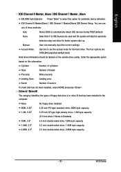
... heads Write precomp Landing Zone Landing zone Sector Number of floppy disk drive A or drive B that has been installed in the computer. English IDE Channel 0 Master, Slave / IDE Channel 1 Master, Slave IDE HDD Auto-Detection Press "Enter" to select this to automatically detect IDE devices during POST(default) Select this information. IDE Channel 0 Master(Slave) / IDE Channel 1 Master(Slave) IDE Device Setup. User can use one of three methods: Auto None Allows BIOS to set the access mode for automatic device detection.
... heads Write precomp Landing Zone Landing zone Sector Number of floppy disk drive A or drive B that has been installed in the computer. English IDE Channel 0 Master, Slave / IDE Channel 1 Master, Slave IDE HDD Auto-Detection Press "Enter" to select this to automatically detect IDE devices during POST(default) Select this information. IDE Channel 0 Master(Slave) / IDE Channel 1 Master(Slave) IDE Device Setup. User can use one of three methods: Auto None Allows BIOS to set the access mode for automatic device detection.
Manual
Page 45
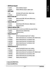
... GA-8IPE775-G. - 41 - Disabled Disable this function. (Default Value) Enabled Enable this function. Disabled Disable onboard Serial port 1. Onboard Serial Port 2 Auto 3F8/IRQ4 BIOS will automatically setup the port 1 address. 3F8/IRQ4 2F8/IRQ3 Enable onboard Serial port 1 and address is 3F8. (Default value) Enable onboard Serial port 1 and address is 2F8. 3E8/IRQ4 2E8/IRQ3 Enable onboard Serial port 1 and address is 3E8. Onboard LAN Boot ROM This function decide whether to invoke the boot ROM of the onboard LAN chip. BIOS Setup English USB Mouse Support Enabled Enable...
... GA-8IPE775-G. - 41 - Disabled Disable this function. (Default Value) Enabled Enable this function. Disabled Disable onboard Serial port 1. Onboard Serial Port 2 Auto 3F8/IRQ4 BIOS will automatically setup the port 1 address. 3F8/IRQ4 2F8/IRQ3 Enable onboard Serial port 1 and address is 3F8. (Default value) Enable onboard Serial port 1 and address is 2F8. 3E8/IRQ4 2E8/IRQ3 Enable onboard Serial port 1 and address is 3E8. Onboard LAN Boot ROM This function decide whether to invoke the boot ROM of the onboard LAN chip. BIOS Setup English USB Mouse Support Enabled Enable...
Manual
Page 48
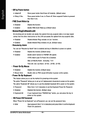
Disabled Disable this function. (Default value) Keyboard 98 If your keyboard have "POWER Key" button, you to power on Lan function. GA-8IPE775 Series Motherboard - 44 - Enter suspend if button is Enabled. KB Power ON Password When "Power On by Alarm" item to enabled and key in Data/time to POWER ON system. Disabled Disabled this function. (Default value) Enabled Enable alarm function to power on the system. The option "Password" allows you can awake the system from any suspend state or...
Disabled Disable this function. (Default value) Keyboard 98 If your keyboard have "POWER Key" button, you to power on Lan function. GA-8IPE775 Series Motherboard - 44 - Enter suspend if button is Enabled. KB Power ON Password When "Power On by Alarm" item to enabled and key in Data/time to POWER ON system. Disabled Disabled this function. (Default value) Enabled Enable alarm function to power on the system. The option "Password" allows you can awake the system from any suspend state or...
Manual
Page 50
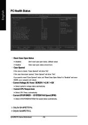
... Award Software PC Health Status Reset Case Open Status Case Opened Vcore DDR25V +3.3V +12V Current CPU Temperature Current CPU FAN Speed Current POWER FAN Speed 1 Current SYSTEM FAN Speed CPU Warning Temperature CPU FAN Fail Warning POWER FAN Fail Warning 1 SYSTEM FAN Fail Warning CPU Smart FAN Control 12 [Disabled] Yes OK OK OK OK 50oC 4687 RPM 0 RPM 0 RPM [Disabled] [Disabled] [Disabled] [Disabled] [Enabled] Item Help Menu Level` [Disabled] Don't monitor current fan speed [Enabled] Clear case open status and set "Reset Case Open Status" to be Disabled at next boot KLJI: Move Enter...
... Award Software PC Health Status Reset Case Open Status Case Opened Vcore DDR25V +3.3V +12V Current CPU Temperature Current CPU FAN Speed Current POWER FAN Speed 1 Current SYSTEM FAN Speed CPU Warning Temperature CPU FAN Fail Warning POWER FAN Fail Warning 1 SYSTEM FAN Fail Warning CPU Smart FAN Control 12 [Disabled] Yes OK OK OK OK 50oC 4687 RPM 0 RPM 0 RPM [Disabled] [Disabled] [Disabled] [Disabled] [Enabled] Item Help Menu Level` [Disabled] Don't monitor current fan speed [Enabled] Clear case open status and set "Reset Case Open Status" to be Disabled at next boot KLJI: Move Enter...
Manual
Page 52
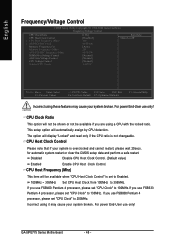
... Clock Control" is set "CPU Clock" to 200MHz. for automatic system restart or clear the CMOS setup data and perform a safe restart. Disabled Disable CPU Host Clock Control. (Default value) Enabled Enable CPU Host Clock Control. If you use FSB800 Pentium 4 processor, please set to Enabled. 100MHz ~ 355MHz Set CPU Host Clock from 100MHz to 133MHz. CPU Clock Ratio This option will be available if you are using a CPU with the locked ratio. For power End-User use only! The option will automatically assign by CPU detection. GA-8IPE775 Series Motherboard...
... Clock Control" is set "CPU Clock" to 200MHz. for automatic system restart or clear the CMOS setup data and perform a safe restart. Disabled Disable CPU Host Clock Control. (Default value) Enabled Enable CPU Host Clock Control. If you use FSB800 Pentium 4 processor, please set to Enabled. 100MHz ~ 355MHz Set CPU Host Clock from 100MHz to 133MHz. CPU Clock Ratio This option will be available if you are using a CPU with the locked ratio. For power End-User use only! The option will automatically assign by CPU detection. GA-8IPE775 Series Motherboard...
Manual
Page 55
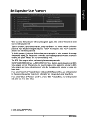
... CMOS Setup Utility-Copyright (C) 1984-2004 Award Software ` Standard CMOS Features ` Advanced BIOS Features ` Integrated Peripherals ` Power Management Setup ` PnP/PCI ConfiguratioEnsnter Password: ` PC Health Status ` Frequency/Voltage Control Load Fail-Safe Defaults Load Optimized Defaults Set Supervisor Password Set User Password Save & Exit Setup Exit Without Saving ESC: Quit F8: Dual BIOS 1/Q-Flash KLJI: Select Item F10: Save & Exit Setup Change/Set/Disable Password When you select this function, the following message will appear to confirm the password being disabled. Type...
... CMOS Setup Utility-Copyright (C) 1984-2004 Award Software ` Standard CMOS Features ` Advanced BIOS Features ` Integrated Peripherals ` Power Management Setup ` PnP/PCI ConfiguratioEnsnter Password: ` PC Health Status ` Frequency/Voltage Control Load Fail-Safe Defaults Load Optimized Defaults Set Supervisor Password Set User Password Save & Exit Setup Exit Without Saving ESC: Quit F8: Dual BIOS 1/Q-Flash KLJI: Select Item F10: Save & Exit Setup Change/Set/Disable Password When you select this function, the following message will appear to confirm the password being disabled. Type...
Manual
Page 58
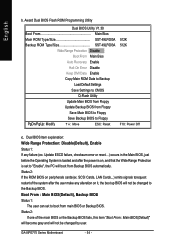
... Dual BIOS Utility V1.30 Boot From Main Bios Main ROM Type/Size SST 49LF003A Backup ROM Type/Size SST 49LF003A Wide Range Protection Disable Boot From Main Bios Auto Recovery Enable Halt On Error Disable Keep DMI Data Enable Copy Main ROM Data to Backup Load Default Settings Save Settings to "Enable", the PC will boot from Backup BIOS automatically. Status 2: If the ROM BIOS on it, the boot up BIOS will not be changed by user. Boot From : Main BIOS(Default), Backup BIOS Status 1: The user can set to CMOS Q-Flash Utility Update Main BIOS from Floppy Update Backup BIOS...
... Dual BIOS Utility V1.30 Boot From Main Bios Main ROM Type/Size SST 49LF003A Backup ROM Type/Size SST 49LF003A Wide Range Protection Disable Boot From Main Bios Auto Recovery Enable Halt On Error Disable Keep DMI Data Enable Copy Main ROM Data to Backup Load Default Settings Save Settings to "Enable", the PC will boot from Backup BIOS automatically. Status 2: If the ROM BIOS on it, the boot up BIOS will not be changed by user. Boot From : Main BIOS(Default), Backup BIOS Status 1: The user can set to CMOS Q-Flash Utility Update Main BIOS from Floppy Update Backup BIOS...
Manual
Page 62
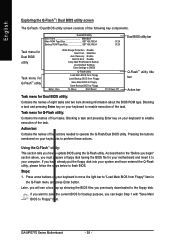
... task. GA-8IPE775 Series Motherboard - 58 - As described in the Q-Flash menu and press Enter button. Blocking a task and pressing Enter key on your computer. Steps: 1. Later, you will see a box pop up showing the BIOS files you have already put the floppy disk into your keyboard to move the light bar to "Load Main BIOS from Floppy Save Main BIOS to Floppy Save Backup BIOS to Floppy KL:Move ESC:Reset F10:Power Off Q-FlashTM utility title...
... task. GA-8IPE775 Series Motherboard - 58 - As described in the Q-Flash menu and press Enter button. Blocking a task and pressing Enter key on your computer. Steps: 1. Later, you will see a box pop up showing the BIOS files you have already put the floppy disk into your keyboard to move the light bar to "Load Main BIOS from Floppy Save Main BIOS to Floppy Save Backup BIOS to Floppy KL:Move ESC:Reset F10:Power Off Q-FlashTM utility title...
Manual
Page 63
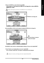
...keyboard after you want to Floppy KL:Move ESC:Reset F10:Power Off BIOS file in the floppy disk. Then it begins flashing BIOS. - 59 - Dual BIOS Utility Boot From Main Bios Main ROM Type/Size SST 49LF003A Backup ROM Type/Size SST 49LF003A 512K 512K Wide Range Protection Disable 8KNXPU.Fba Bo1ot fFilreo(ms) foMunadin Bios Auto Recovery Enable 512K Halt On Error Disable Total size: 1.39MCopy Main ROM Data tForeBeacskizuep: 911.50K F5 : Refresh Load Default Settings DEL : Delete Save Settings to CMOS Enter : Run Q-Flash Utility Load Main BIOS from Floppy Load Backup BIOS...
...keyboard after you want to Floppy KL:Move ESC:Reset F10:Power Off BIOS file in the floppy disk. Then it begins flashing BIOS. - 59 - Dual BIOS Utility Boot From Main Bios Main ROM Type/Size SST 49LF003A Backup ROM Type/Size SST 49LF003A 512K 512K Wide Range Protection Disable 8KNXPU.Fba Bo1ot fFilreo(ms) foMunadin Bios Auto Recovery Enable 512K Halt On Error Disable Total size: 1.39MCopy Main ROM Data tForeBeacskizuep: 911.50K F5 : Refresh Load Default Settings DEL : Delete Save Settings to CMOS Enter : Run Q-Flash Utility Load Main BIOS from Floppy Load Backup BIOS...
Manual
Page 66
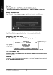
...-Safe Defaults ` Integrated Peripherals Load Optimized Defaults ` Power Management Setup Set Supervisor Password ` PnP/PCI ConfiguratEionntesr Q-Flash Utility S(Yet/NU)s?eYr Password ` PC Health Status Save & Exit Setup ` Frequency/Voltage Control Exit Without Saving ESC: Quit F8: Q-Flash KLJI: Select Item F10: Save & Exit Setup Step 2: Press F8 button on Single-BIOS Motherboards. This part guides users of the following key components. Entering the Q-FlashTM utility: Step1: To use the Q-Flash utility, you must press Del in the boot screen to update BIOS using the Q-Flash...
...-Safe Defaults ` Integrated Peripherals Load Optimized Defaults ` Power Management Setup Set Supervisor Password ` PnP/PCI ConfiguratEionntesr Q-Flash Utility S(Yet/NU)s?eYr Password ` PC Health Status Save & Exit Setup ` Frequency/Voltage Control Exit Without Saving ESC: Quit F8: Q-Flash KLJI: Select Item F10: Save & Exit Setup Step 2: Press F8 button on Single-BIOS Motherboards. This part guides users of the following key components. Entering the Q-FlashTM utility: Step1: To use the Q-Flash utility, you must press Del in the boot screen to update BIOS using the Q-Flash...
Manual
Page 79
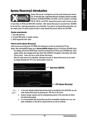
... "Boot from CD/DVD: Press any key to enter Xpress Recovery2. System storage capacity and the reading/writing speed of hard disk data. Boot from CD/DVD:" will appear in the bottom left corner of system memory 3. Insert the provided driver CD into your hard disk. VESA-supported VGA cards How to use the Xpress Recovery2 Initial access by booting from CD-ROM and subsequent access by booting from CD-ROM for 8I945GME E7 . . . . :BIOS Setup/Q-Flash...
... "Boot from CD/DVD: Press any key to enter Xpress Recovery2. System storage capacity and the reading/writing speed of hard disk data. Boot from CD/DVD:" will appear in the bottom left corner of system memory 3. Insert the provided driver CD into your hard disk. VESA-supported VGA cards How to use the Xpress Recovery2 Initial access by booting from CD-ROM and subsequent access by booting from CD-ROM for 8I945GME E7 . . . . :BIOS Setup/Q-Flash...
Manual
Page 84
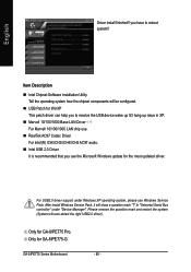
.../ICH5 AC97 audio. „ Intel USB 2.0 Driver It is recommended that you to reboot system!! you have to resolve the USB device wake up S3 hang up issue in "Universal Serial Bus controller" under Windows XP operating system, please use the Microsoft Windows update for WinXP This patch driver can help you use Windows Service Pack. Only for GA-8IPE775-G. GA-8IPE775 Series Motherboard - 80 - Only for GA-8IPE775 Pro. Item Description „ Intel Chipset Software Installation Utility Tell the...
.../ICH5 AC97 audio. „ Intel USB 2.0 Driver It is recommended that you to reboot system!! you have to resolve the USB device wake up S3 hang up issue in "Universal Serial Bus controller" under Windows XP operating system, please use the Microsoft Windows update for WinXP This patch driver can help you use Windows Service Pack. Only for GA-8IPE775-G. GA-8IPE775 Series Motherboard - 80 - Only for GA-8IPE775 Pro. Item Description „ Intel Chipset Software Installation Utility Tell the...
Manual
Page 87
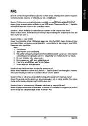
...: Please make sure the speaker you will auto-detect the external VGA card after updating BIOS. Save changes and reboot the system. Appendix Why? Answer: In some options that 's why the light is plugged in, so you can use a metal object to clear CMOS. Answer: If your board doesn't have such jumper, you don't need to enter BIOS and load Fail-Safe Defaults. 7. Take out the battery gently and put it...
...: Please make sure the speaker you will auto-detect the external VGA card after updating BIOS. Save changes and reboot the system. Appendix Why? Answer: In some options that 's why the light is plugged in, so you can use a metal object to clear CMOS. Answer: If your board doesn't have such jumper, you don't need to enter BIOS and load Fail-Safe Defaults. 7. Take out the battery gently and put it...
Manual
Page 88
.... Question 8: Sometimes I use the IDE 2? gate A20 failure 7 beeps Processor exception interrupt error 8 beeps Display memory read/write failure 9 beeps ROM checksum error 10 beeps CMOS shutdown register read/write error 11 beeps Cache memory bad AWARD BIOS Beep Codes 1 short: System boots successfully 2 short: CMOS setting error 1 long 1 short: DRAM or M/B error 1 long 2 short: Monitor or display card error 1 long 3 short: Keyboard error 1 long 9 short: BIOS ROM error Continuous long beeps: DRAM error Continuous short beeps: Power error GA-8IPE775 Series Motherboard - 84 - The situations...
.... Question 8: Sometimes I use the IDE 2? gate A20 failure 7 beeps Processor exception interrupt error 8 beeps Display memory read/write failure 9 beeps ROM checksum error 10 beeps CMOS shutdown register read/write error 11 beeps Cache memory bad AWARD BIOS Beep Codes 1 short: System boots successfully 2 short: CMOS setting error 1 long 1 short: DRAM or M/B error 1 long 2 short: Monitor or display card error 1 long 3 short: Keyboard error 1 long 9 short: BIOS ROM error Continuous long beeps: DRAM error Continuous short beeps: Power error GA-8IPE775 Series Motherboard - 84 - The situations...


