Manual
Page 6
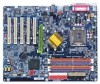
...Table of Content Warning 4 Chapter 1 Introduction 5 Features Summary 5 GA-8IPE775 Series Motherboard Layout 7 Block Diagram 8 Chapter 2 Hardware Installation Process 11 Step 1: Install the Central Processing Unit (CPU 12 Step 1-1: Installation of the CPU 12 Step 1-2: Installation of the Heatsink 13 Step 2: Installation of ...Step 4-2: Connectors Introduction 19 Chapter 3 BIOS Setup 31 The Main Menu (For example: BIOS Ver. : 8IPE775 Pro.D4 32 Standard CMOS Features 34 Advanced BIOS Features 37 Integrated Peripherals 39 Power Management Setup 43 GA-8IPE775 Series Motherboard - 2 -
...Table of Content Warning 4 Chapter 1 Introduction 5 Features Summary 5 GA-8IPE775 Series Motherboard Layout 7 Block Diagram 8 Chapter 2 Hardware Installation Process 11 Step 1: Install the Central Processing Unit (CPU 12 Step 1-1: Installation of the CPU 12 Step 1-2: Installation of the Heatsink 13 Step 2: Installation of ...Step 4-2: Connectors Introduction 19 Chapter 3 BIOS Setup 31 The Main Menu (For example: BIOS Ver. : 8IPE775 Pro.D4 32 Standard CMOS Features 34 Advanced BIOS Features 37 Integrated Peripherals 39 Power Management Setup 43 GA-8IPE775 Series Motherboard - 2 -
Manual
Page 9
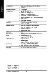
... Memory Slots On-Board IDE On-Board Floppy On-Board Peripherals y Supports the latest Intel® Pentium® 4 Socket 775 CPU y Supports 533/800MHz FSB y L2 cache varies with CPU y GA-8IPE775 Series Motherboard: GA-8IPE775 Pro/GA-8IPE775-G/GA-8IPE775 y North Bridge: Intel® 865PE y South Bridge: Intel® ICH5 y 4 184-pin DDR DIMM sockets y Supports Dual channel DDR400... and DDR266 memory module. (Note 1) Due to standard PC architecture, a certain amount of memory size will support DDR400/DDR333/DDR266 memory module. Introduction Only for GA-8IPE775 Pro. - 5 -
... Memory Slots On-Board IDE On-Board Floppy On-Board Peripherals y Supports the latest Intel® Pentium® 4 Socket 775 CPU y Supports 533/800MHz FSB y L2 cache varies with CPU y GA-8IPE775 Series Motherboard: GA-8IPE775 Pro/GA-8IPE775-G/GA-8IPE775 y North Bridge: Intel® 865PE y South Bridge: Intel® ICH5 y 4 184-pin DDR DIMM sockets y Supports Dual channel DDR400... and DDR266 memory module. (Note 1) Due to standard PC architecture, a certain amount of memory size will support DDR400/DDR333/DDR266 memory module. Introduction Only for GA-8IPE775 Pro. - 5 -
Manual
Page 10
GA-8IPE775 Series Motherboard - 6 - English On-Board LAN On-Board IEEE1394 On-Board Sound Serial ATA Hardware Monitor I/O Control PS/2 Connector BIOS Additional Features Overclocking Form Factor y ... y IT8712 y PS/2 Keyboard interface and PS/2 Mouse interface y Licensed AWARD BIOS y Supports Dual BIOS /Q-Flash y Supports EasyTune y Supports @BIOS y Supports CPU Smart Fan Control function y Over Voltage (DDR/AGP/CPU) by BIOS y Over Clock (DDR/AGP/CPU/PCI) by BIOS y ATX size form factor; 30.5cm x 24.4cm Only for GA-8IPE775-G. Only for GA-8IPE775 Pro.
GA-8IPE775 Series Motherboard - 6 - English On-Board LAN On-Board IEEE1394 On-Board Sound Serial ATA Hardware Monitor I/O Control PS/2 Connector BIOS Additional Features Overclocking Form Factor y ... y IT8712 y PS/2 Keyboard interface and PS/2 Mouse interface y Licensed AWARD BIOS y Supports Dual BIOS /Q-Flash y Supports EasyTune y Supports @BIOS y Supports CPU Smart Fan Control function y Over Voltage (DDR/AGP/CPU) by BIOS y Over Clock (DDR/AGP/CPU/PCI) by BIOS y ATX size form factor; 30.5cm x 24.4cm Only for GA-8IPE775-G. Only for GA-8IPE775 Pro.
Manual
Page 15
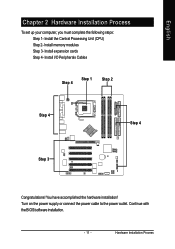
Install I/O Peripherals Cables Step 4 Step 1 Step 2 Step 4 Step 4 Step 3 Congratulations! Turn on the power supply or connect the power cable to the power outlet. Continue with the BIOS/software installation. - 11 - Hardware Installation Process Install the Central Processing Unit (CPU) Step 2- Install memory modules Step 3- Install expansion cards Step 4- English Chapter 2 Hardware Installation Process To set up your computer, you must complete the following steps: Step 1- You have accomplished the hardware installation!
Install I/O Peripherals Cables Step 4 Step 1 Step 2 Step 4 Step 4 Step 3 Congratulations! Turn on the power supply or connect the power cable to the power outlet. Continue with the BIOS/software installation. - 11 - Hardware Installation Process Install the Central Processing Unit (CPU) Step 2- Install memory modules Step 3- Install expansion cards Step 4- English Chapter 2 Hardware Installation Process To set up your computer, you must complete the following steps: Step 1- You have accomplished the hardware installation!
Manual
Page 16
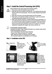
... to your computer system requires all of heat sink paste between the CPU and heatsink. 4. OS: An operation system that supports HT Technology - Please take note of the one indented corner of the CPU. 3. GA-8IPE775 Series Motherboard - 12 - Please add an even layer of the following conditions: 1. Please set the frequency beyond hardware...
... to your computer system requires all of heat sink paste between the CPU and heatsink. 4. OS: An operation system that supports HT Technology - Please take note of the one indented corner of the CPU. 3. GA-8IPE775 Series Motherboard - 12 - Please add an even layer of the following conditions: 1. Please set the frequency beyond hardware...
Manual
Page 17
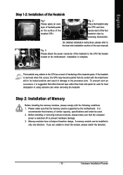
...damage. 3. Hardware Installation Process To prevent such an occurrence, it is suggested that the computer power is removed when this occurs, the CPU may adhere to the processor pins. Before installing or removing memory modules, please make sure that memory of the heatsink to insert the module..., please switch the direction. - 13 - Fig. 2 Place the heatsink atop the CPU and then secure each of the heatsink paste. The heatsink may become pulled from its socket with the following conditions: 1. Please make sure that...
...damage. 3. Hardware Installation Process To prevent such an occurrence, it is suggested that the computer power is removed when this occurs, the CPU may adhere to the processor pins. Before installing or removing memory modules, please make sure that memory of the heatsink to insert the module..., please switch the direction. - 13 - Fig. 2 Place the heatsink atop the CPU and then secure each of the heatsink paste. The heatsink may become pulled from its socket with the following conditions: 1. Please make sure that...
Manual
Page 24
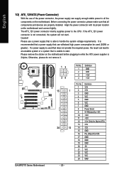
... on the motherboard before plugging in while the ATX power supplier is not connected, the system will not start . Otherwise, please do not remove it. GA-8IPE775 Series Motherboard 13 24 13 1 24 12 - 20 - English 1/2) ATX_12V/ATX (Power Connector) With the use a power supply that is unable to all ... be used that does not provide the required power, the result can lead to an unstable system or a system that is able to the CPU. Align the power connector with its proper location on the motherboard. Please use of the power connector, the power supply can supply enough stable ...
... on the motherboard before plugging in while the ATX power supplier is not connected, the system will not start . Otherwise, please do not remove it. GA-8IPE775 Series Motherboard 13 24 13 1 24 12 - 20 - English 1/2) ATX_12V/ATX (Power Connector) With the use a power supply that is unable to all ... be used that does not provide the required power, the result can lead to an unstable system or a system that is able to the CPU. Align the power connector with its proper location on the motherboard. Please use of the power connector, the power supply can supply enough stable ...
Manual
Page 25
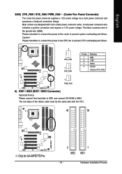
.... The black connector wire is the ground wire (GND). Please remember to connect the power to the CPU fan to prevent CPU overheating and failure. 1 CPU_FAN 1 SYS_FAN Pin No. 1 2 3 4 Definition GND +12V Sense Control (Only for GA-8IPE775 Pro. 2 IDE2 1 IDE1 - 21 - Hardware Installation Process Please remember to connect the power to the cooler...
.... The black connector wire is the ground wire (GND). Please remember to connect the power to the CPU fan to prevent CPU overheating and failure. 1 CPU_FAN 1 SYS_FAN Pin No. 1 2 3 4 Definition GND +12V Sense Control (Only for GA-8IPE775 Pro. 2 IDE2 1 IDE1 - 21 - Hardware Installation Process Please remember to connect the power to the cooler...
Manual
Page 37
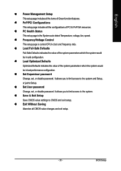
... - z Frequency/Voltage Control This setup page is the System auto detect Temperature, voltage, fan, speed. BIOS Setup z PC Health Status This setup page is control CPU's clock and frequency ratio. z Set Supervisor password Change, set , or disable password. z Exit Without Saving Abandon all the configurations of the system parameters which the...
... - z Frequency/Voltage Control This setup page is the System auto detect Temperature, voltage, fan, speed. BIOS Setup z PC Health Status This setup page is control CPU's clock and frequency ratio. z Set Supervisor password Change, set , or disable password. z Exit Without Saving Abandon all the configurations of the system parameters which the...

Manual
Page 40
... memory installed on Drive A & B are 3 mode Floppy Drives. NO Errors The system boot will determine the amount of base (or conventional) memory installed in the CPU's memory address map. Base Memory The POST of the BIOS will not stop if an error is detected during the POST. The value of the... except a keyboard error. (Default value) All, But Diskette The system boot will be stopped. All, But Disk/Key Memory The system boot will be prompted. GA-8IPE775 Series Motherboard - 36 -
... memory installed on Drive A & B are 3 mode Floppy Drives. NO Errors The system boot will determine the amount of base (or conventional) memory installed in the CPU's memory address map. Base Memory The POST of the BIOS will not stop if an error is detected during the POST. The value of the... except a keyboard error. (Default value) All, But Diskette The system boot will be stopped. All, But Disk/Key Memory The system boot will be prompted. GA-8IPE775 Series Motherboard - 36 -
Manual
Page 41
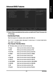
Press to OS2 or DR-DOS # CPU Hyper-Threading Limit CPUID Max. Select your boot device priority by LAN. Select your boot device priority by USB-CDROM. Select your boot device priority ...
Press to OS2 or DR-DOS # CPU Hyper-Threading Limit CPUID Max. Select your boot device priority by LAN. Select your boot device priority by USB-CDROM. Select your boot device priority ...
Manual
Page 42
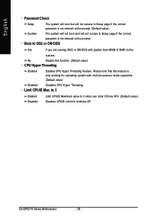
...OS2 or DR-DOS Yes If you are running OS/2 or DR-DOS with multi processors mode supported. (Default value) Disabled Disables CPU Hyper Threading. GA-8IPE775 Series Motherboard - 38 - English Password Check Setup The system will boot but will not access to Setup page if the correct ... access to Setup page if the correct password is only working for windows XP. Please note that this function. (Default value) CPU Hyper-Threading Enabled Enables CPU Hyper Threading Feature. Boot to 3 when use older OS like NT4. (Default value) Disables CPUID Limit for operating system with...
...OS2 or DR-DOS Yes If you are running OS/2 or DR-DOS with multi processors mode supported. (Default value) Disabled Disables CPU Hyper Threading. GA-8IPE775 Series Motherboard - 38 - English Password Check Setup The system will boot but will not access to Setup page if the correct ... access to Setup page if the correct password is only working for windows XP. Please note that this function. (Default value) CPU Hyper-Threading Enabled Enables CPU Hyper Threading Feature. Boot to 3 when use older OS like NT4. (Default value) Disables CPUID Limit for operating system with...
Manual
Page 50
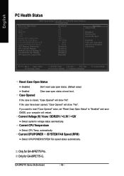
..., set to "Enabled" and save CMOS, your computer will restart. Current CPU/POWER /SYSTEM FAN Speed (RPM) Detect CPU/POWER/SYSTEM Fan speed status automatically. GA-8IPE775 Series Motherboard - 46 - If the case is closed, "Case Opened" will show "No". Current CPU Temperature Detect CPU Temp. automatically. Current Voltage (V) Vcore / DDR25V / +3.3V / +12V Detect system's voltage...
..., set to "Enabled" and save CMOS, your computer will restart. Current CPU/POWER /SYSTEM FAN Speed (RPM) Detect CPU/POWER/SYSTEM Fan speed status automatically. GA-8IPE775 Series Motherboard - 46 - If the case is closed, "Case Opened" will show "No". Current CPU Temperature Detect CPU Temp. automatically. Current Voltage (V) Vcore / DDR25V / +3.3V / +12V Detect system's voltage...

Manual
Page 51
... will run at high speed. Only for GA-8IPE775-G. - 47 - English CPU Warning Temperature 60oC / 140oF Monitor CPU Temp. at 90oC / 194oF. at 80oC / 176oF. 90oC / 194oF Monitor CPU Temp. When the CPU temperature is between 50 and 70 degrees Celsius, CPU fan will run at full speed. BIOS Setup CPU Smart FAN Control Disabled Enabled Disable this...
... will run at high speed. Only for GA-8IPE775-G. - 47 - English CPU Warning Temperature 60oC / 140oF Monitor CPU Temp. at 90oC / 194oF. at 80oC / 176oF. 90oC / 194oF Monitor CPU Temp. When the CPU temperature is between 50 and 70 degrees Celsius, CPU fan will run at full speed. BIOS Setup CPU Smart FAN Control Disabled Enabled Disable this...
Manual
Page 52
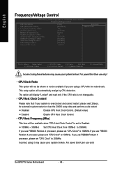
...perform a safe restart. English Frequency/Voltage Control CMOS Setup Utility-Copyright (C) 1984-2004 Award Software Frequency/Voltage Control CPU Clock Ratio CPU Host Clock Control x CPU Host Frequency (Mhz) x AGP/PCI/SRC Fixed Memory Frequency For Memory Frequency (Mhz) AGP/PCI/SRC Frequency ...set "CPU Clock" to 200MHz. CPU Host Clock Control Please note that if your system broken. If you use FSB400 Pentium 4 processor, please set "CPU Clock" to 100MHz.If you use FSB533 Pentium 4 processor, please set "CPU Clock" to 133MHz. For power End-User use only! GA-8IPE775 Series ...
...perform a safe restart. English Frequency/Voltage Control CMOS Setup Utility-Copyright (C) 1984-2004 Award Software Frequency/Voltage Control CPU Clock Ratio CPU Host Clock Control x CPU Host Frequency (Mhz) x AGP/PCI/SRC Fixed Memory Frequency For Memory Frequency (Mhz) AGP/PCI/SRC Frequency ...set "CPU Clock" to 200MHz. CPU Host Clock Control Please note that if your system broken. If you use FSB400 Pentium 4 processor, please set "CPU Clock" to 100MHz.If you use FSB533 Pentium 4 processor, please set "CPU Clock" to 133MHz. For power End-User use only! GA-8IPE775 Series ...
Manual
Page 53
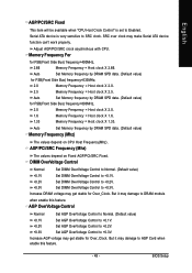
...= Host clock X 2.0. 1.6 Memory Frequency = Host clock X 1.6. 1.33 Memory Frequency = Host clock X 1.33. Adjust AGP/PCI/SRC clock asychrohous with CPU. Auto Set Memory frequency by DRAM SPD data. (Default value) Memory Frequency (Mhz) The values depend on Fixed AGP/PCI/SRC Fixed. English AGP/PCI.../SRC Fixed This item will be available when "CPU Host Clock Control" is very sensitive to SRC clock. Memory Frequency For for Over_Clock. DIMM OverVoltage Control Normal Set DIMM OverVoltage Control ...
...= Host clock X 2.0. 1.6 Memory Frequency = Host clock X 1.6. 1.33 Memory Frequency = Host clock X 1.33. Adjust AGP/PCI/SRC clock asychrohous with CPU. Auto Set Memory frequency by DRAM SPD data. (Default value) Memory Frequency (Mhz) The values depend on Fixed AGP/PCI/SRC Fixed. English AGP/PCI.../SRC Fixed This item will be available when "CPU Host Clock Control" is very sensitive to SRC clock. Memory Frequency For for Over_Clock. DIMM OverVoltage Control Normal Set DIMM OverVoltage Control ...
Manual
Page 54
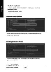
... F10: Save & Exit Setup Load Optimized Defaults Selecting this field loads the factory defaults for GA-8IPE775 Pro. English CPU OverVoltage Control Supports adjustable CPU Vcore from 0.8375V to 1.7600V. (Default value: Normal) Normal CPU Vcore Display your CPU Vcore Voltage. GA-8IPE775 Series Motherboard - 50 - Load Fail-Safe Defaults CMOS Setup Utility-Copyright (C) 1984-2004 Award Software...
... F10: Save & Exit Setup Load Optimized Defaults Selecting this field loads the factory defaults for GA-8IPE775 Pro. English CPU OverVoltage Control Supports adjustable CPU Vcore from 0.8375V to 1.7600V. (Default value: Normal) Normal CPU Vcore Display your CPU Vcore Voltage. GA-8IPE775 Series Motherboard - 50 - Load Fail-Safe Defaults CMOS Setup Utility-Copyright (C) 1984-2004 Award Software...
Manual
Page 89
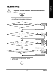
...memory module vertically into the DIMM slot. No Make sure the jumper setting are set properly. Failure has been excluded. Yes Check if the CPU cooling fan attached to CPU_FAN properly? No Yes Please isolate the short pin. START Turn off the power and unplug the AC power cable..., then remove all jumper settings (such as CPU system bus speed, frequency ratio, voltage and etc.) are correct. Yes Failure has been excluded. Insert the VGA card. English Troubleshooting If you...
...memory module vertically into the DIMM slot. No Make sure the jumper setting are set properly. Failure has been excluded. Yes Check if the CPU cooling fan attached to CPU_FAN properly? No Yes Please isolate the short pin. START Turn off the power and unplug the AC power cable..., then remove all jumper settings (such as CPU system bus speed, frequency ratio, voltage and etc.) are correct. Yes Failure has been excluded. Insert the VGA card. English Troubleshooting If you...
Manual
Page 90
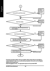
...Reboot after keyboard and mouse have been plugged in. Failure has been excluded. Yes Reinstall Windows OS, and reinstall add-on and CPU fan running? No Perhaps your keyboard or keyboard connector is defective. It is possible that No your VGA card / VGA slot ... procedure unable to solve your problem, please contact with your question to the service mail via Gigabyte website technical support zone (http://www.gigabyte.com.tw). Failure has been excluded. GA-8IPE775 Series Motherboard - 86 - Or, you could be provided ASAP. The problem could submit your...
...Reboot after keyboard and mouse have been plugged in. Failure has been excluded. Yes Reinstall Windows OS, and reinstall add-on and CPU fan running? No Perhaps your keyboard or keyboard connector is defective. It is possible that No your VGA card / VGA slot ... procedure unable to solve your problem, please contact with your question to the service mail via Gigabyte website technical support zone (http://www.gigabyte.com.tw). Failure has been excluded. GA-8IPE775 Series Motherboard - 86 - Or, you could be provided ASAP. The problem could submit your...

Manual
Page 92
GA-8IPE775 Series Motherboard - 88 - English Acronyms Acronyms ACPI APM AGP AMR ACR BIOS CPU CMOS CRIMM CNR DMA DMI DIMM DRM DRAM DDR ECP ESCD ECC EMC EPP ESD FDD FSB HDD IDE IRQ Meaning Advanced Configuration and Power ...
GA-8IPE775 Series Motherboard - 88 - English Acronyms Acronyms ACPI APM AGP AMR ACR BIOS CPU CMOS CRIMM CNR DMA DMI DIMM DRM DRAM DDR ECP ESCD ECC EMC EPP ESD FDD FSB HDD IDE IRQ Meaning Advanced Configuration and Power ...


