Manual
Page 8
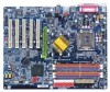
... a metal object, such as the power supply case. 3. Just cut the bottom portion of the spacers (the spacer may damage the board or cause board malfunctioning. Sometimes you can still attach the motherboard to attach the spacers, do not have one, touch both of your hands to a...be near the fixing hole, otherwise it may be careful of your hands). Installing the motherboard to the mounting holes. Unplug your computer. 1. GA-8IPE775 Series Motherboard - 4 - Hold components by the hole. If the motherboard has mounting holes, but they don't line up with the components ...
... a metal object, such as the power supply case. 3. Just cut the bottom portion of the spacers (the spacer may damage the board or cause board malfunctioning. Sometimes you can still attach the motherboard to attach the spacers, do not have one, touch both of your hands to a...be near the fixing hole, otherwise it may be careful of your hands). Installing the motherboard to the mounting holes. Unplug your computer. 1. GA-8IPE775 Series Motherboard - 4 - Hold components by the hole. If the motherboard has mounting holes, but they don't line up with the components ...
Manual
Page 9
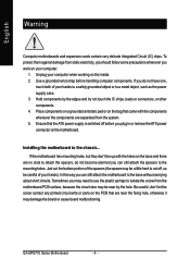
.... - 5 - Introduction English Chapter 1 Introduction Features Summary CPU Motherboard Chipset Memory Slots On-Board IDE On-Board Floppy On-Board Peripherals y Supports the latest Intel® Pentium® 4 Socket 775 CPU y Supports 533/800MHz FSB y L2 cache varies with CPU y GA-8IPE775 Series Motherboard: GA-8IPE775 Pro/GA-8IPE775-G/GA-8IPE775 y North Bridge: Intel® 865PE y South Bridge: Intel® ICH5 y 4 184...
.... - 5 - Introduction English Chapter 1 Introduction Features Summary CPU Motherboard Chipset Memory Slots On-Board IDE On-Board Floppy On-Board Peripherals y Supports the latest Intel® Pentium® 4 Socket 775 CPU y Supports 533/800MHz FSB y L2 cache varies with CPU y GA-8IPE775 Series Motherboard: GA-8IPE775 Pro/GA-8IPE775-G/GA-8IPE775 y North Bridge: Intel® 865PE y South Bridge: Intel® ICH5 y 4 184...
Manual
Page 10
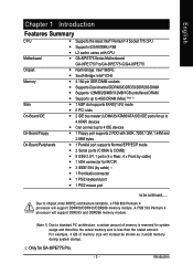
Only for GA-8IPE775 Pro. English On-Board LAN On-Board IEEE1394 On-Board Sound Serial ATA Hardware Monitor I/O Control PS/2 Connector BIOS Additional Features Overclocking Form Factor y Build in Marvell 8001 Chipset (10/100/1000 Mbit) y 1 RJ45 port y ... y Over Voltage (DDR/AGP/CPU) by BIOS y Over Clock (DDR/AGP/CPU/PCI) by BIOS y ATX size form factor; 30.5cm x 24.4cm Only for GA-8IPE775-G. GA-8IPE775 Series Motherboard - 6 -
Only for GA-8IPE775 Pro. English On-Board LAN On-Board IEEE1394 On-Board Sound Serial ATA Hardware Monitor I/O Control PS/2 Connector BIOS Additional Features Overclocking Form Factor y Build in Marvell 8001 Chipset (10/100/1000 Mbit) y 1 RJ45 port y ... y Over Voltage (DDR/AGP/CPU) by BIOS y Over Clock (DDR/AGP/CPU/PCI) by BIOS y ATX size form factor; 30.5cm x 24.4cm Only for GA-8IPE775-G. GA-8IPE775 Series Motherboard - 6 -
Manual
Page 30
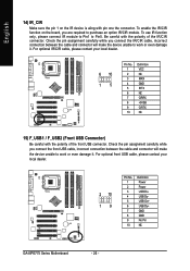
... cable, please contact your local dealer. 2 10 19 Pin No. 1 2 3 4 5 6 7 8 9 10 Definition Power Power USB DxUSB DyUSB Dx+ USB Dy+ GND GND No Pin NC GA-8IPE775 Series Motherboard - 26 - To use IR function only, please connect IR module to Pin1 to Pin5. To enable the IR/CIR function on the IR... device is aling with pin one the connector. English 14) IR_CIR Make sure the pin 1 on the board, you connect the IR/CIR cable, incorrect connection between the cable and connector will make the device unable to work or even damage it . For...
... cable, please contact your local dealer. 2 10 19 Pin No. 1 2 3 4 5 6 7 8 9 10 Definition Power Power USB DxUSB DyUSB Dx+ USB Dy+ GND GND No Pin NC GA-8IPE775 Series Motherboard - 26 - To use IR function only, please connect IR module to Pin1 to Pin5. To enable the IR/CIR function on the IR... device is aling with pin one the connector. English 14) IR_CIR Make sure the pin 1 on the board, you connect the IR/CIR cable, incorrect connection between the cable and connector will make the device unable to work or even damage it . For...
Manual
Page 87
...the light of general asked questions based on a specific motherboard model, please log on power. 6. If your board has a Clear CMOS jumper, please refer to load Fail-Safe Defaults (Or Load BIOS Defaults) after updating ... and that were included in previous BIOS after it aside for one minute). 4. Press Del to see some boards, a small amount of electricity is kept on standby after computer shuts down ? Save changes and reboot the...speaker to disable the onboard VGA. - 83 - Appendix Answer: Gigabyte motherboards will be able to enter BIOS and load Fail-Safe Defaults. 7.
...the light of general asked questions based on a specific motherboard model, please log on power. 6. If your board has a Clear CMOS jumper, please refer to load Fail-Safe Defaults (Or Load BIOS Defaults) after updating ... and that were included in previous BIOS after it aside for one minute). 4. Press Del to see some boards, a small amount of electricity is kept on standby after computer shuts down ? Save changes and reboot the...speaker to disable the onboard VGA. - 83 - Appendix Answer: Gigabyte motherboards will be able to enter BIOS and load Fail-Safe Defaults. 7.


