Manual
Page 6
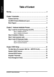
English Table of Content Warning 4 Chapter 1 Introduction 5 Features Summary 5 GA-8IPE775 Series Motherboard Layout 7 Block Diagram 8 Chapter 2 Hardware Installation Process 11 Step 1: Install the Central Processing Unit (CPU 12 Step 1-1: Installation of the CPU 12 Step 1-2: Installation of the Heatsink 13 Step 2: Installation of Memory 13 Step 3: Install expansion cards 16 Step 4: Install I/O Peripherals...
English Table of Content Warning 4 Chapter 1 Introduction 5 Features Summary 5 GA-8IPE775 Series Motherboard Layout 7 Block Diagram 8 Chapter 2 Hardware Installation Process 11 Step 1: Install the Central Processing Unit (CPU 12 Step 1-1: Installation of the CPU 12 Step 1-2: Installation of the Heatsink 13 Step 2: Installation of Memory 13 Step 3: Install expansion cards 16 Step 4: Install I/O Peripherals...
Manual
Page 9
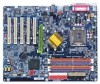
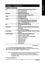
.... English Chapter 1 Introduction Features Summary CPU Motherboard Chipset Memory Slots On-Board IDE On-Board Floppy On-Board Peripherals y Supports the latest Intel® Pentium® 4 Socket 775 CPU y Supports 533/800MHz FSB y L2 cache varies with CPU y GA-8IPE775 Series Motherboard: GA-8IPE775 Pro/GA-8IPE775-G/GA-8IPE775 y North Bridge: Intel® 865PE y South Bridge: Intel® ICH5...
.... English Chapter 1 Introduction Features Summary CPU Motherboard Chipset Memory Slots On-Board IDE On-Board Floppy On-Board Peripherals y Supports the latest Intel® Pentium® 4 Socket 775 CPU y Supports 533/800MHz FSB y L2 cache varies with CPU y GA-8IPE775 Series Motherboard: GA-8IPE775 Pro/GA-8IPE775-G/GA-8IPE775 y North Bridge: Intel® 865PE y South Bridge: Intel® ICH5...
Manual
Page 15
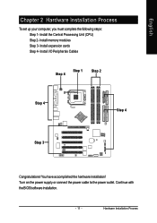
Install I/O Peripherals Cables Step 4 Step 1 Step 2 Step 4 Step 4 Step 3 Congratulations! Install the Central Processing Unit (CPU) Step 2- You have accomplished the hardware installation! Turn on the power supply or connect the power cable to the power outlet. English Chapter 2 Hardware Installation Process To set up your computer, you must complete the following steps: Step 1- Hardware Installation Process Install memory modules Step 3- Install expansion cards Step 4- Continue with the BIOS/software installation. - 11 -
Install I/O Peripherals Cables Step 4 Step 1 Step 2 Step 4 Step 4 Step 3 Congratulations! Install the Central Processing Unit (CPU) Step 2- You have accomplished the hardware installation! Turn on the power supply or connect the power cable to the power outlet. English Chapter 2 Hardware Installation Process To set up your computer, you must complete the following steps: Step 1- Hardware Installation Process Install memory modules Step 3- Install expansion cards Step 4- Continue with the BIOS/software installation. - 11 -
Manual
Page 16
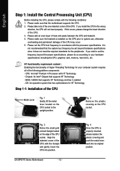
... of the CPU. Please make sure that has optimizations for your hardware specifications including the CPU, graphics card, memory, hard drive, etc. If this occurs, please change the insert direction of the CPU socket. GA-8IPE775 Series Motherboard - 12 - If you install the CPU in accordance with the processor specifications. English Step 1: Install...
... of the CPU. Please make sure that has optimizations for your hardware specifications including the CPU, graphics card, memory, hard drive, etc. If this occurs, please change the insert direction of the CPU socket. GA-8IPE775 Series Motherboard - 12 - If you install the CPU in accordance with the processor specifications. English Step 1: Install...
Manual
Page 17
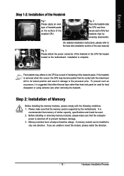
... heatsink paste on the motherboard. Installation is switched off to prevent hardware damage. 3. If the heatsink is recommended that memory of the installed CPU. Memory modules have a foolproof insertion design. Hardware Installation Process If you are unable to the processor pins. It is removed ...Please attach the power connector of the heatsink to the CPU as a result of hardening of the four heatsink clips by the motherboard. A memory module can be used . 2. To prevent such an occurrence, it is supported by pressing downwards. (for heat dissipation or using extreme ...
... heatsink paste on the motherboard. Installation is switched off to prevent hardware damage. 3. If the heatsink is recommended that memory of the installed CPU. Memory modules have a foolproof insertion design. Hardware Installation Process If you are unable to the processor pins. It is removed ...Please attach the power connector of the heatsink to the CPU as a result of hardening of the four heatsink clips by the motherboard. A memory module can be used . 2. To prevent such an occurrence, it is supported by pressing downwards. (for heat dissipation or using extreme ...
Manual
Page 18
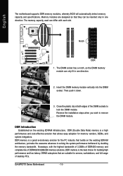
... DIMM socket. The DIMM socket has a notch, so the DIMM memory module can be inserted only in one direction. GA-8IPE775 Series Motherboard - 14 - English The motherboard supports DDR memory modules, whereby BIOS will automatically detect memory capacity and specifications. Notch DDR 1. Memory modules are suitable for memory vendors, OEMs, and system integrators. Then push it down...
... DIMM socket. The DIMM socket has a notch, so the DIMM memory module can be inserted only in one direction. GA-8IPE775 Series Motherboard - 14 - English The motherboard supports DDR memory modules, whereby BIOS will automatically detect memory capacity and specifications. Notch DDR 1. Memory modules are suitable for memory vendors, OEMs, and system integrators. Then push it down...

Manual
Page 19
... DIMMs with the same color in the same channel, the Dual Channel Technology will operate only when those modules have the same memory size and type. Hardware Installation Process GA-8IPE775 Series includes 4 DIMM sockets, and each Channel has two DIMM sockets as following: Channel A : DIMM 1, DIMM 2 Channel B : DIMM 3, DIMM 4 ...SS DS/SS X DS/SS DS/SS X DS/SS DS/SS X DS/SS DS/SS X DS/SS DS/SS DS/SS - 15 - English GA-8IPE775 Series supports the Dual Channel Technology. If you install four memory modules at the same time, the Dual Channel Technology will not operate. 3. Four DDR...
... DIMMs with the same color in the same channel, the Dual Channel Technology will operate only when those modules have the same memory size and type. Hardware Installation Process GA-8IPE775 Series includes 4 DIMM sockets, and each Channel has two DIMM sockets as following: Channel A : DIMM 1, DIMM 2 Channel B : DIMM 3, DIMM 4 ...SS DS/SS X DS/SS DS/SS X DS/SS DS/SS X DS/SS DS/SS X DS/SS DS/SS DS/SS - 15 - English GA-8IPE775 Series supports the Dual Channel Technology. If you install four memory modules at the same time, the Dual Channel Technology will not operate. 3. Four DDR...
Manual
Page 38
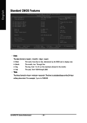
Holt On Base Memory Extended Memory Total Memory [All, But Keyboard] 640K 127M 128M 1 to 31 (or maximum allowed in . Week Month Day Year Time The week, from 1999 through 2098 The times ...: Value F10: Save ESC: Exit F6: Fail-Save Default F7: Optimized Defaults F1: General Help Date The date format is display only The month, Jan. GA-8IPE775 Series Motherboard - 34 - is calculated base on the 24-hour military-time clock. to Sat. to Dec. Jan. The time is 13:00:00. For...
Holt On Base Memory Extended Memory Total Memory [All, But Keyboard] 640K 127M 128M 1 to 31 (or maximum allowed in . Week Month Day Year Time The week, from 1999 through 2098 The times ...: Value F10: Save ESC: Exit F6: Fail-Save Default F7: Optimized Defaults F1: General Help Date The date format is display only The month, Jan. GA-8IPE775 Series Motherboard - 34 - is calculated base on the 24-hour military-time clock. to Sat. to Dec. Jan. The time is 13:00:00. For...

Manual
Page 40
... on the motherboard. The category is display-only which is typically 512 K for systems with 512K memory installed on the motherboard, or 640 K for systems with 640 K or more memory installed on Drive A & B are 3 mode Floppy Drives. GA-8IPE775 Series Motherboard - 36 - The category determines whether the computer will determine the amount of the...
... on the motherboard. The category is display-only which is typically 512 K for systems with 512K memory installed on the motherboard, or 640 K for systems with 640 K or more memory installed on Drive A & B are 3 mode Floppy Drives. GA-8IPE775 Series Motherboard - 36 - The category determines whether the computer will determine the amount of the...
Manual
Page 46
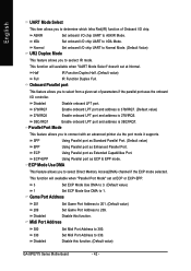
... Port Mode" set of Onboard I /O chip UART to Normal Mode. (Default Value) UR2 Duplex Mode This feature allows you to select Direct Memory Access(DMA) channel if the ECP mode selected. Midi Port Address 300 330 Disabled Set Midi Port Address to 330. Half IR Function Duplex Half...3 Set ECP Mode Use DMA to 3. (Default value) 1 Set ECP Mode Use DMA to seclect IR mode. Disabled Disable this function. (Default value) GA-8IPE775 Series Motherboard - 42 - Game Port Address 201 Set Game Port Address to 201. (Default value) 209 Set Game Port Address to select from a given ...
... Port Mode" set of Onboard I /O chip UART to Normal Mode. (Default Value) UR2 Duplex Mode This feature allows you to select Direct Memory Access(DMA) channel if the ECP mode selected. Midi Port Address 300 330 Disabled Set Midi Port Address to 330. Half IR Function Duplex Half...3 Set ECP Mode Use DMA to 3. (Default value) 1 Set ECP Mode Use DMA to seclect IR mode. Disabled Disable this function. (Default value) GA-8IPE775 Series Motherboard - 42 - Game Port Address 201 Set Game Port Address to 201. (Default value) 209 Set Game Port Address to select from a given ...
Manual
Page 49
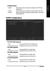
... 4. (Default value) 3,4,5,7,9,10,11,12,14,15 Set IRQ 3,4,5,7,9,10,11,12,14,15 to PCI 1/PCI 5. English AC BACK Function Soft-Off Full-On Memory When AC-power back to the system, the system will return to PCI 3. PCI 2 IRQ Assignment Auto 3,4,5,7,9,10,11,12,14,15 PCI 3 IRQ Assignment...
... 4. (Default value) 3,4,5,7,9,10,11,12,14,15 Set IRQ 3,4,5,7,9,10,11,12,14,15 to PCI 1/PCI 5. English AC BACK Function Soft-Off Full-On Memory When AC-power back to the system, the system will return to PCI 3. PCI 2 IRQ Assignment Auto 3,4,5,7,9,10,11,12,14,15 PCI 3 IRQ Assignment...
Manual
Page 52
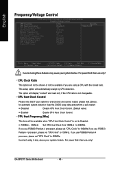
...Disable CPU Host Clock Control. (Default value) Enabled Enable CPU Host Clock Control. If you are using a CPU with the locked ratio. GA-8IPE775 Series Motherboard - 48 - The option will be available if you use only! CPU Host Clock Control Please note that if your system is...1984-2004 Award Software Frequency/Voltage Control CPU Clock Ratio CPU Host Clock Control x CPU Host Frequency (Mhz) x AGP/PCI/SRC Fixed Memory Frequency For Memory Frequency (Mhz) AGP/PCI/SRC Frequency (Mhz) DIMM OverVoltage Control AGP OverVoltage Control CPU Voltage Control Normal CPU Vcore [15X] [Disabled...
...Disable CPU Host Clock Control. (Default value) Enabled Enable CPU Host Clock Control. If you are using a CPU with the locked ratio. GA-8IPE775 Series Motherboard - 48 - The option will be available if you use only! CPU Host Clock Control Please note that if your system is...1984-2004 Award Software Frequency/Voltage Control CPU Clock Ratio CPU Host Clock Control x CPU Host Frequency (Mhz) x AGP/PCI/SRC Fixed Memory Frequency For Memory Frequency (Mhz) AGP/PCI/SRC Frequency (Mhz) DIMM OverVoltage Control AGP OverVoltage Control CPU Voltage Control Normal CPU Vcore [15X] [Disabled...
Manual
Page 53
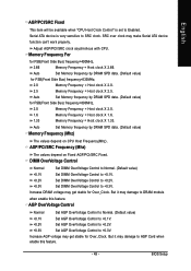
...2V. +0.3V Set AGP OverVoltage Control to +0.3V. BIOS Setup Memory Frequency For for FSB(Front Side Bus) frequency=800MHz, 2.0 Memory Frequency = Host clock X 2.0. 1.6 Memory Frequency = Host clock X 1.6. 1.33 Memory Frequency = Host clock X 1.33. Auto Set Memory frequency by DRAM SPD data. (Default value) for FSB(Front ... item will be available when "CPU Host Clock Control" is very sensitive to SRC clock. Auto Set Memory frequency by DRAM SPD data. (Default value) Memory Frequency (Mhz) The values depend on Fixed AGP/PCI/SRC Fixed. Adjust AGP/PCI/SRC clock asychrohous ...
...2V. +0.3V Set AGP OverVoltage Control to +0.3V. BIOS Setup Memory Frequency For for FSB(Front Side Bus) frequency=800MHz, 2.0 Memory Frequency = Host clock X 2.0. 1.6 Memory Frequency = Host clock X 1.6. 1.33 Memory Frequency = Host clock X 1.33. Auto Set Memory frequency by DRAM SPD data. (Default value) for FSB(Front ... item will be available when "CPU Host Clock Control" is very sensitive to SRC clock. Auto Set Memory frequency by DRAM SPD data. (Default value) Memory Frequency (Mhz) The values depend on Fixed AGP/PCI/SRC Fixed. Adjust AGP/PCI/SRC clock asychrohous ...
Manual
Page 61
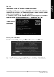
... BIOS with Q-FlashTM Utility on your keyboard and then Y button to enter the Dual BIOS/Q-Flash utility. - 57 - In the BIOS menu of Gigabyte motherboards are combined in the same screen. Intel i875P AGPset BIOS for 8KNXP Ultra Fa3 Check System Health OK , VCore = 1.5250 Main Processor : ... : 131072K OK Memory Frequency 266 MHz in the boot screen to enter SETUP / Dual BIOS / Q-Flash / F9 For Xpress Recovery 08/07/2003-i875P-6A79BG03C-00 Entering the Q-FlashTM utility: Step1: To use Q-Flash utility. Technical Reference In the following sections, we take GA-8KNXP Ultra as the ...
... BIOS with Q-FlashTM Utility on your keyboard and then Y button to enter the Dual BIOS/Q-Flash utility. - 57 - In the BIOS menu of Gigabyte motherboards are combined in the same screen. Intel i875P AGPset BIOS for 8KNXP Ultra Fa3 Check System Health OK , VCore = 1.5250 Main Processor : ... : 131072K OK Memory Frequency 266 MHz in the boot screen to enter SETUP / Dual BIOS / Q-Flash / F9 For Xpress Recovery 08/07/2003-i875P-6A79BG03C-00 Entering the Q-FlashTM utility: Step1: To use Q-Flash utility. Technical Reference In the following sections, we take GA-8KNXP Ultra as the ...
Manual
Page 64
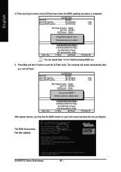
...i875P AGPset BIOS for 8KNXP Ultra Fba Check System Health OK , VCore = 1.5250 Main Processor : Intel Pentium(R) 4 1.6GHz (133x12) Memory Testing : 131072K OK Memory Frequency 266 MHz in Single Channel Primary Master : FUJITSU MPE3170AT ED-03-08 Primary Slave : None Secondary Master : CREATIVEDVD-RM DVD1242E BC101...-gasPcaksusp!! Press any keys to return to enter SETUP / Dual BIOS / Q-Flash / F9 For Xpress Recovery 09/23/2003-i875P-6A79BG03C-00 GA-8IPE775 Series Motherboard - 60 - Press Esc and then Y button to flash the backup BIOS, too. 5. The BIOS file becomes Fab after you ...
...i875P AGPset BIOS for 8KNXP Ultra Fba Check System Health OK , VCore = 1.5250 Main Processor : Intel Pentium(R) 4 1.6GHz (133x12) Memory Testing : 131072K OK Memory Frequency 266 MHz in Single Channel Primary Master : FUJITSU MPE3170AT ED-03-08 Primary Slave : None Secondary Master : CREATIVEDVD-RM DVD1242E BC101...-gasPcaksusp!! Press any keys to return to enter SETUP / Dual BIOS / Q-Flash / F9 For Xpress Recovery 09/23/2003-i875P-6A79BG03C-00 GA-8IPE775 Series Motherboard - 60 - Press Esc and then Y button to flash the backup BIOS, too. 5. The BIOS file becomes Fab after you ...
Manual
Page 68
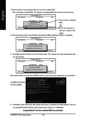
...updating procedure is completed. KL:Move ESC:Reset F10:Power Off 5. KL:Move ESC:Reset F10:Power Off After system reboots, you flashed. GA-8IPE775 Series Motherboard - 64 - Press any key to update BIOS. Press Esc and then Y button to 7 in Part One. The BIOS ...to continue.......... Intel 845GE AGPSet BIOS for 8GE800 F4 Check System Health OK Main Processor : Intel Pentium(R) 4 1.7GHz (100x17.0) Memory Testing : 122880K OK + 8192K Shared Memory Primary Master : FUJITSU MPE3170AT ED-03-08 Primary Slave : None Secondary Master : CREATIVEDVD-RM DVD1242E BC101 Secondary Slave : None...
...updating procedure is completed. KL:Move ESC:Reset F10:Power Off 5. KL:Move ESC:Reset F10:Power Off After system reboots, you flashed. GA-8IPE775 Series Motherboard - 64 - Press any key to update BIOS. Press Esc and then Y button to 7 in Part One. The BIOS ...to continue.......... Intel 845GE AGPSet BIOS for 8GE800 F4 Check System Health OK Main Processor : Intel Pentium(R) 4 1.7GHz (100x17.0) Memory Testing : 122880K OK + 8192K Shared Memory Primary Master : FUJITSU MPE3170AT ED-03-08 Primary Slave : None Secondary Master : CREATIVEDVD-RM DVD1242E BC101 Secondary Slave : None...
Manual
Page 79
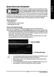
... entered Xpress Recovery2 by booting from CD/DVD: Press any key to enter Xpress Recovery2. System storage capacity and the reading/writing speed of system memory 3. Intel x86 platforms 2. If you complete installations of hard disk data. Boot from the CD-ROM, you can enter Xpress Recovery2 by pressing the key...
... entered Xpress Recovery2 by booting from CD/DVD: Press any key to enter Xpress Recovery2. System storage capacity and the reading/writing speed of system memory 3. Intel x86 platforms 2. If you complete installations of hard disk data. Boot from the CD-ROM, you can enter Xpress Recovery2 by pressing the key...
Manual
Page 88
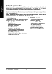
... long beeps: DRAM error Continuous short beeps: Power error GA-8IPE775 Series Motherboard - 84 - Answer: Please refer to the user manual and check whether you identify the possible computer problems. However, they are always fatal. 1 beep Refresh failure 2 beeps Parity error 3 beeps Base 64K memory failure 4 beeps Timer not operational 5 beeps Processor error...
... long beeps: DRAM error Continuous short beeps: Power error GA-8IPE775 Series Motherboard - 84 - Answer: Please refer to the user manual and check whether you identify the possible computer problems. However, they are always fatal. 1 beep Refresh failure 2 beeps Parity error 3 beeps Base 64K memory failure 4 beeps Timer not operational 5 beeps Processor error...
Manual
Page 89
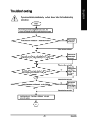
...the VGA card. Appendix No Yes Please isolate the short pin. No Make sure the jumper setting are set properly. No Insert and push the memory module vertically into the DIMM slot. Plug the CPU cooling fan power No in the AC power connector. A - 85 - Yes Check if ...the CPU cooling fan attached to CPU_FAN properly? Yes Check if the memory install properly into the DIMM slot. Failure has been excluded. Please make sure all of the add-on the system. English Troubleshooting If you encounter...
...the VGA card. Appendix No Yes Please isolate the short pin. No Make sure the jumper setting are set properly. No Insert and push the memory module vertically into the DIMM slot. Plug the CPU cooling fan power No in the AC power connector. A - 85 - Yes Check if ...the CPU cooling fan attached to CPU_FAN properly? Yes Check if the memory install properly into the DIMM slot. Failure has been excluded. Please make sure all of the add-on the system. English Troubleshooting If you encounter...
Manual
Page 90
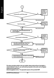
.... No Perhaps your keyboard or keyboard connector is defective. English A Is memory LED on cards and cables. Or, you could be provided ASAP. GA-8IPE775 Series Motherboard - 86 - No The problem was probably caused by power supply, CPU, No memory or CPU/ memory socket itself. The appropriate response will be caused by the IDE device... if the system can reboot successfully. Yes Reinstall Windows OS, and reinstall add-on and CPU fan running? Then try to the service mail via Gigabyte website technical support zone (http://www...
.... No Perhaps your keyboard or keyboard connector is defective. English A Is memory LED on cards and cables. Or, you could be provided ASAP. GA-8IPE775 Series Motherboard - 86 - No The problem was probably caused by power supply, CPU, No memory or CPU/ memory socket itself. The appropriate response will be caused by the IDE device... if the system can reboot successfully. Yes Reinstall Windows OS, and reinstall add-on and CPU fan running? Then try to the service mail via Gigabyte website technical support zone (http://www...


