
Manual
Page 1
...128 Pro graphics cards made by adjusting the jumper. Therefore, AG32S(G) will work fine with 2X/4X mode AGP slot. The GA-8IPE775 Series (or any AGP 4X/8X only) motherboards might not function properly, If you install PCI cards, please remove the Dual BIOS label from PCI slots if there is ...compliance with 2X(3.3V)/4X(1.5V) mode AGP slot, but they support 2X (3.3V) only. Note : Although Gigabyte's AG32S(G) graphics card is based on...
...128 Pro graphics cards made by adjusting the jumper. Therefore, AG32S(G) will work fine with 2X/4X mode AGP slot. The GA-8IPE775 Series (or any AGP 4X/8X only) motherboards might not function properly, If you install PCI cards, please remove the Dual BIOS label from PCI slots if there is ...compliance with 2X(3.3V)/4X(1.5V) mode AGP slot, but they support 2X (3.3V) only. Note : Although Gigabyte's AG32S(G) graphics card is based on...
Manual
Page 2
0 The author assumes no responsibility for any errors or omissions that may appear in this document nor does the author make a commitment to update the information contained herein. 0 Third-party brands and names are the property of their respective owners. 0 Please do not remove any labels on motherboard, this may void the warranty of this motherboard. 0 Due to rapid change in technology, some of the specifications might be out of date before publication of this booklet.
0 The author assumes no responsibility for any errors or omissions that may appear in this document nor does the author make a commitment to update the information contained herein. 0 Third-party brands and names are the property of their respective owners. 0 Please do not remove any labels on motherboard, this may void the warranty of this motherboard. 0 Due to rapid change in technology, some of the specifications might be out of date before publication of this booklet.

Manual
Page 4
... the following two conditions: (1) This device may not cause harmful and (2) this device must accept any inference received, including that the product Product Name: Motherboard Model Number: GA-8IPE775 Pro/GA-8IPE775-G /GA-8IPE775 Conforms to the following specifications: FCC Part 15, Subpart B, Section 15.107(a) and Section 15.109 (a),Class B Digital Device Supplementary Information: This device...
... the following two conditions: (1) This device may not cause harmful and (2) this device must accept any inference received, including that the product Product Name: Motherboard Model Number: GA-8IPE775 Pro/GA-8IPE775-G /GA-8IPE775 Conforms to the following specifications: FCC Part 15, Subpart B, Section 15.107(a) and Section 15.109 (a),Class B Digital Device Supplementary Information: This device...

Manual
Page 5
GA-8IPE775 Series Intel® Pentium® 4 Socket 775 Processor Motherboard USER'S MANUAL Pentium® 4 Processor Motherboard Rev. 1004 12ME-8IPE775-1004
GA-8IPE775 Series Intel® Pentium® 4 Socket 775 Processor Motherboard USER'S MANUAL Pentium® 4 Processor Motherboard Rev. 1004 12ME-8IPE775-1004
Manual
Page 6
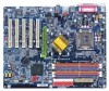
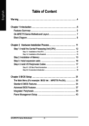
English Table of Content Warning 4 Chapter 1 Introduction 5 Features Summary 5 GA-8IPE775 Series Motherboard Layout 7 Block Diagram 8 Chapter 2 Hardware Installation Process 11 Step 1: Install the Central Processing Unit (CPU 12 Step 1-1: Installation of the CPU 12... Cables 17 Step 4-1: I/O Back Panel Introduction 17 Step 4-2: Connectors Introduction 19 Chapter 3 BIOS Setup 31 The Main Menu (For example: BIOS Ver. : 8IPE775 Pro.D4 32 Standard CMOS Features 34 Advanced BIOS Features 37 Integrated Peripherals 39 Power Management Setup 43 GA-8IPE775 Series Motherboard - 2 -
English Table of Content Warning 4 Chapter 1 Introduction 5 Features Summary 5 GA-8IPE775 Series Motherboard Layout 7 Block Diagram 8 Chapter 2 Hardware Installation Process 11 Step 1: Install the Central Processing Unit (CPU 12 Step 1-1: Installation of the CPU 12... Cables 17 Step 4-1: I/O Back Panel Introduction 17 Step 4-2: Connectors Introduction 19 Chapter 3 BIOS Setup 31 The Main Menu (For example: BIOS Ver. : 8IPE775 Pro.D4 32 Standard CMOS Features 34 Advanced BIOS Features 37 Integrated Peripherals 39 Power Management Setup 43 GA-8IPE775 Series Motherboard - 2 -
Manual
Page 8
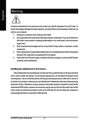
...the edges and try not touch the IC chips, leads or connectors, or other components. 4. Installing the motherboard to isolate the screw from the system. 5. GA-8IPE775 Series Motherboard - 4 - Unplug your hands to a safely grounded object or to the base without worrying about short circuits... may need to use the plastic springs to the chassis... Just cut off before handling computer components. English Warning Computer motherboards and expansion cards contain very delicate Integrated Circuit (IC) chips. To protect them against damage from static electricity, you should...
...the edges and try not touch the IC chips, leads or connectors, or other components. 4. Installing the motherboard to isolate the screw from the system. 5. GA-8IPE775 Series Motherboard - 4 - Unplug your hands to a safely grounded object or to the base without worrying about short circuits... may need to use the plastic springs to the chassis... Just cut off before handling computer components. English Warning Computer motherboards and expansion cards contain very delicate Integrated Circuit (IC) chips. To protect them against damage from static electricity, you should...
Manual
Page 9
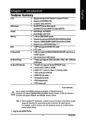
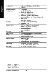
...-Board Floppy On-Board Peripherals y Supports the latest Intel® Pentium® 4 Socket 775 CPU y Supports 533/800MHz FSB y L2 cache varies with CPU y GA-8IPE775 Series Motherboard: GA-8IPE775 Pro/GA-8IPE775-G/GA-8IPE775 y North Bridge: Intel® 865PE y South Bridge: Intel® ICH5 y 4 184-pin DDR DIMM sockets y Supports Dual channel DDR400/DDR333/DDR266 DIMM y Supports 128MB...
...-Board Floppy On-Board Peripherals y Supports the latest Intel® Pentium® 4 Socket 775 CPU y Supports 533/800MHz FSB y L2 cache varies with CPU y GA-8IPE775 Series Motherboard: GA-8IPE775 Pro/GA-8IPE775-G/GA-8IPE775 y North Bridge: Intel® 865PE y South Bridge: Intel® ICH5 y 4 184-pin DDR DIMM sockets y Supports Dual channel DDR400/DDR333/DDR266 DIMM y Supports 128MB...
Manual
Page 10
... y Over Voltage (DDR/AGP/CPU) by BIOS y Over Clock (DDR/AGP/CPU/PCI) by BIOS y ATX size form factor; 30.5cm x 24.4cm Only for GA-8IPE775-G. Only for GA-8IPE775 Pro. GA-8IPE775 Series Motherboard - 6 -
... y Over Voltage (DDR/AGP/CPU) by BIOS y Over Clock (DDR/AGP/CPU/PCI) by BIOS y ATX size form factor; 30.5cm x 24.4cm Only for GA-8IPE775-G. Only for GA-8IPE775 Pro. GA-8IPE775 Series Motherboard - 6 -
Manual
Page 12
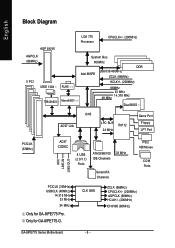
... 33 MHz IDE Channels Serial ATA Channels PS/2 KB/Mouse COM Ports PCICLK (33MHz) USBCLK (48MHz) 14.318 MHz 33 MHz 24 MHz Only for GA-8IPE775-G. CLK GEN ZCLK (66MHz) CPUCLK+/- (200MHz) AGPCLK (66MHz) HCLK+/- (200MHz) ICH3V66 (66MHz) GA-8IPE775 Series Motherboard - 8 - Only for GA-8IPE775 Pro.
... 33 MHz IDE Channels Serial ATA Channels PS/2 KB/Mouse COM Ports PCICLK (33MHz) USBCLK (48MHz) 14.318 MHz 33 MHz 24 MHz Only for GA-8IPE775-G. CLK GEN ZCLK (66MHz) CPUCLK+/- (200MHz) AGPCLK (66MHz) HCLK+/- (200MHz) ICH3V66 (66MHz) GA-8IPE775 Series Motherboard - 8 - Only for GA-8IPE775 Pro.

Manual
Page 14
English GA-8IPE775 Series Motherboard - 10 -
English GA-8IPE775 Series Motherboard - 10 -
Manual
Page 16
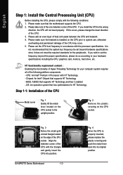
... make sure that supports HT Technology and has it does not meet the required standards for the peripherals. BIOS: A BIOS that the motherboard supports the CPU. 2. Fig. 2 Remove the plastic covering on the edge of Hyper-Threading Technology for HT Technology Step 1-1: Installation of...permanent damage of the CPU. 3. Please take note of the one indented corner of heat sink paste between the CPU and heatsink. 4. GA-8IPE775 Series Motherboard - 12 - Fig. 3 Notice the small gold colored triangle located on the CPU socket. Please make sure the heatsink is installed on...
... make sure that supports HT Technology and has it does not meet the required standards for the peripherals. BIOS: A BIOS that the motherboard supports the CPU. 2. Fig. 2 Remove the plastic covering on the edge of Hyper-Threading Technology for HT Technology Step 1-1: Installation of...permanent damage of the CPU. 3. Please take note of the one indented corner of heat sink paste between the CPU and heatsink. 4. GA-8IPE775 Series Motherboard - 12 - Fig. 3 Notice the small gold colored triangle located on the CPU socket. Please make sure the heatsink is installed on...

Manual
Page 17
... Step 1-2: Installation of the Heatsink Fig.1 Please apply an even layer of heatsink paste on the motherboard. Fig. 2 Place the heatsink atop the CPU and then secure each of the four heatsink clips by the motherboard. Please make sure that the memory used for detailed installation instructions, please refer to the heat...
... Step 1-2: Installation of the Heatsink Fig.1 Please apply an even layer of heatsink paste on the motherboard. Fig. 2 Place the heatsink atop the CPU and then secure each of the four heatsink clips by the motherboard. Please make sure that the memory used for detailed installation instructions, please refer to the heat...
Manual
Page 18
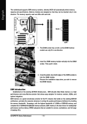
... and full range of desktop PCs. The DIMM socket has a notch, so the DIMM memory module can only fit in one direction. 2. GA-8IPE775 Series Motherboard - 14 - Notch DDR 1. Close the plastic clip at both edges of DDR400/333/266/200 memory solutions, DDR memory is a great ...the highest bandwidth of 3.2GB/s of DDR400 memory and complete line of the DIMM sockets to remove the DIMM module. English The motherboard supports DDR memory modules, whereby BIOS will automatically detect memory capacity and specifications. Reverse the installation steps when you wish to lock...
... and full range of desktop PCs. The DIMM socket has a notch, so the DIMM memory module can only fit in one direction. 2. GA-8IPE775 Series Motherboard - 14 - Notch DDR 1. Close the plastic clip at both edges of DDR400/333/266/200 memory solutions, DDR memory is a great ...the highest bandwidth of 3.2GB/s of DDR400 memory and complete line of the DIMM sockets to remove the DIMM module. English The motherboard supports DDR memory modules, whereby BIOS will automatically detect memory capacity and specifications. Reverse the installation steps when you wish to lock...
Manual
Page 20
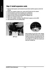
... you try to the onboard AGP slot and press firmly down on the slot .Make sure your AGP card is locked by the small white- GA-8IPE775 Series Motherboard - 16 - Replace your computer's chassis cover, screws and slot bracket from the computer. 3. AGP Card Please carefully pull out the small white- English Step... the related expansion card's instruction document before install the expansion card into expansion slot in the slot. 5. Power on the card are indeed seated in motherboard. 4. drawable bar.
... you try to the onboard AGP slot and press firmly down on the slot .Make sure your AGP card is locked by the small white- GA-8IPE775 Series Motherboard - 16 - Replace your computer's chassis cover, screws and slot bracket from the computer. 3. AGP Card Please carefully pull out the small white- English Step... the related expansion card's instruction document before install the expansion card into expansion slot in the slot. 5. Power on the card are indeed seated in motherboard. 4. drawable bar.
Manual
Page 22
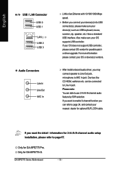
Have a standard USB interface. Devices like CD-ROM, walkman etc. Only for GA-8IPE775-G. Also make sure your device(s) such as USB keyboard,mouse, scanner, zip, speaker..etc. If ..., you want the detail information for optional SUR_CEN cable. Please note: You are able to Line-In jack. Only for GA-8IPE775 Pro. can refer to enable 8-channel function you connect your device(s) into USB connector(s), please make sure your nearest dealer ...USB 3 Audio Connectors Line In Line Out MIC In LAN is fast Ethernet with 10/100/1000 Mbps speed. GA-8IPE775 Series Motherboard - 18 -
Have a standard USB interface. Devices like CD-ROM, walkman etc. Only for GA-8IPE775-G. Also make sure your device(s) such as USB keyboard,mouse, scanner, zip, speaker..etc. If ..., you want the detail information for optional SUR_CEN cable. Please note: You are able to Line-In jack. Only for GA-8IPE775 Pro. can refer to enable 8-channel function you connect your device(s) into USB connector(s), please make sure your nearest dealer ...USB 3 Audio Connectors Line In Line Out MIC In LAN is fast Ethernet with 10/100/1000 Mbps speed. GA-8IPE775 Series Motherboard - 18 -
Manual
Page 24
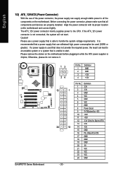
...-12V GND PS_ON(soft On/Off) GND GND GND -5V VCC VCC VCC GND Align the power connector with its proper location on the motherboard and connect tightly. Please use of the power connector, the power supply can withstand high power consumption be used that does not provide the ... system or a system that can supply enough stable power to all components and devices are properly installed. If a power supply is unable to start . GA-8IPE775 Series Motherboard 13 24 13 1 24 12 - 20 - Otherwise, please do not remove it. It is recommended that a power supply that is used (300W...
...-12V GND PS_ON(soft On/Off) GND GND GND -5V VCC VCC VCC GND Align the power connector with its proper location on the motherboard and connect tightly. Please use of the power connector, the power supply can withstand high power consumption be used that does not provide the ... system or a system that can supply enough stable power to all components and devices are properly installed. If a power supply is unable to start . GA-8IPE775 Series Motherboard 13 24 13 1 24 12 - 20 - Otherwise, please do not remove it. It is recommended that a power supply that is used (300W...
Manual
Page 26
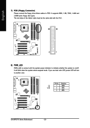
It supports 360K, 1.2M, 720K, 1.44M and 2.88M bytes floppy disk types. It will turn to indicate whether the system is connect with the system power indicator to another color. Pin No. Definition 1 MPD+ 1 2 MPD- 3 MPD- If you use dual color LED, power LED will blink when the system enters suspend mode. GA-8IPE775 Series Motherboard - 22 - The red stripe of the ribbon cable must be the same side with the Pin1. 34 33 2 1 8) PWR_LED PWR_LED is on/off. English 7) FDD (Floppy Connector) Please connect the floppy drive ribbon cables to FDD.
It supports 360K, 1.2M, 720K, 1.44M and 2.88M bytes floppy disk types. It will turn to indicate whether the system is connect with the system power indicator to another color. Pin No. Definition 1 MPD+ 1 2 MPD- 3 MPD- If you use dual color LED, power LED will blink when the system enters suspend mode. GA-8IPE775 Series Motherboard - 22 - The red stripe of the ribbon cable must be the same side with the Pin1. 34 33 2 1 8) PWR_LED PWR_LED is on/off. English 7) FDD (Floppy Connector) Please connect the floppy drive ribbon cables to FDD.
Manual
Page 28
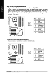
... contact your nearest dealer for optional SUR_CEN cable. 12 78 Pin No. 1 2 3 4 5 6 7 8 Definition SUR OUTL SUR OUTR GND No Pin CENTER_OUT BASS_OUT AUX_L AUX_R GA-8IPE775 Series Motherboard - 24 - To find out if the chassis you are buying support front audio connector, please contact your dealer. Also please make sure the pin assigment...
... contact your nearest dealer for optional SUR_CEN cable. 12 78 Pin No. 1 2 3 4 5 6 7 8 Definition SUR OUTL SUR OUTR GND No Pin CENTER_OUT BASS_OUT AUX_L AUX_R GA-8IPE775 Series Motherboard - 24 - To find out if the chassis you are buying support front audio connector, please contact your dealer. Also please make sure the pin assigment...
Manual
Page 30
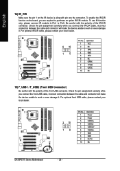
..., please contact your local dealer. 2 10 19 Pin No. 1 2 3 4 5 6 7 8 9 10 Definition Power Power USB DxUSB DyUSB Dx+ USB Dy+ GND GND No Pin NC GA-8IPE775 Series Motherboard - 26 - To enable the IR/CIR function on the IR device is aling with pin one the connector. English 14) IR_CIR Make sure the pin...
..., please contact your local dealer. 2 10 19 Pin No. 1 2 3 4 5 6 7 8 9 10 Definition Power Power USB DxUSB DyUSB Dx+ USB Dy+ GND GND No Pin NC GA-8IPE775 Series Motherboard - 26 - To enable the IR/CIR function on the IR device is aling with pin one the connector. English 14) IR_CIR Make sure the pin...
Manual
Page 32
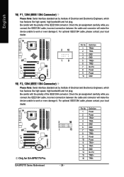
...) F1_1394 (IEEE 1394 Connector) Please Note: Serial interface standard set by Institute of the IEEE1394 connector. Only for GA-8IPE775 Pro. Check the pin assignment carefully while you connect the IEEE1394 cable, incorrect connection between the cable and connector will... Power Power GND 19) F2_1394 (IEEE 1394 Connector) Please Note: Serial interface standard set by Institute of the IEEE1394 connector. GA-8IPE775 Series Motherboard - 28 - Be careful with the polarity of Electrical and Electronics Engineers, which has features like high speed, high bandwidth and hot plug...
...) F1_1394 (IEEE 1394 Connector) Please Note: Serial interface standard set by Institute of the IEEE1394 connector. Only for GA-8IPE775 Pro. Check the pin assignment carefully while you connect the IEEE1394 cable, incorrect connection between the cable and connector will... Power Power GND 19) F2_1394 (IEEE 1394 Connector) Please Note: Serial interface standard set by Institute of the IEEE1394 connector. GA-8IPE775 Series Motherboard - 28 - Be careful with the polarity of Electrical and Electronics Engineers, which has features like high speed, high bandwidth and hot plug...


