
Owners Manual
Page 1
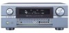
"SERIAL NO. Be sure to offer, read these instructions carefully and use the set properly. PLEASE RECORD UNIT SERIAL NUMBER ATTACHED TO THE REAR OF THE CABINET FOR FUTURE REFERENCE" AV SURROUND RECEIVER AVR-3805 OPERATING INSTRUCTIONS CH SEL ENTER 2 We greatly appreciate your purchase of the AVR-3805. 2 To be sure you take maximum advantage of all the features the AVR-3805 has to keep this manual for future reference, should any questions or problems arise.
"SERIAL NO. Be sure to offer, read these instructions carefully and use the set properly. PLEASE RECORD UNIT SERIAL NUMBER ATTACHED TO THE REAR OF THE CABINET FOR FUTURE REFERENCE" AV SURROUND RECEIVER AVR-3805 OPERATING INSTRUCTIONS CH SEL ENTER 2 We greatly appreciate your purchase of the AVR-3805. 2 To be sure you take maximum advantage of all the features the AVR-3805 has to keep this manual for future reference, should any questions or problems arise.
Owners Manual
Page 2
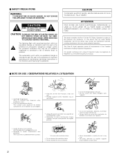
... exclamation point within the product's enclosure that may be of sufficient magnitude to constitute a risk of important operating and maintenance (servicing) instructions in any interference received, including interference that may not cause harmful interference, and (2) this device must accept any way. • Ne jamais démonter ou modifier l'appareil d'une mani...
... exclamation point within the product's enclosure that may be of sufficient magnitude to constitute a risk of important operating and maintenance (servicing) instructions in any interference received, including interference that may not cause harmful interference, and (2) this device must accept any way. • Ne jamais démonter ou modifier l'appareil d'une mani...
Owners Manual
Page 4
... differ from the actual set To prevent short circuits or damaged wires in addition to the main unit: q Operating instructions.....1 w Warranty ( for choosing the DENON AVR-3805 Digital A / V Surround Receiver. As this unit or any other components. 4 inch/10 cm or more CH SEL ENTER 4 inch/10 cm or more Wall 4 If this happens...
... differ from the actual set To prevent short circuits or damaged wires in addition to the main unit: q Operating instructions.....1 w Warranty ( for choosing the DENON AVR-3805 Digital A / V Surround Receiver. As this unit or any other components. 4 inch/10 cm or more CH SEL ENTER 4 inch/10 cm or more Wall 4 If this happens...

Owners Manual
Page 18
... indicator. w INPUT SIGNAL CHANNEL indicator The channels included in ZONE2/REC SELECT. REC OUT mode is operating. 18 o DENON LINK indicator This lights during playback in a DENON LINK connection. !0 V.OFF indicator This lights when the operation of the video circuit has been turned off. !1 AL24 ...selected in the AUTO tuning mode. !4 TUNED indicator This lights when an FM/AM broadcast has been received. !5 STEREO indicator This lights when an FM stereo broadcast has been received. !6 Decoder indicator This lights when each decoder is selected in the input source will light. e...
... indicator. w INPUT SIGNAL CHANNEL indicator The channels included in ZONE2/REC SELECT. REC OUT mode is operating. 18 o DENON LINK indicator This lights during playback in a DENON LINK connection. !0 V.OFF indicator This lights when the operation of the video circuit has been turned off. !1 AL24 ...selected in the AUTO tuning mode. !4 TUNED indicator This lights when an FM/AM broadcast has been received. !5 STEREO indicator This lights when an FM stereo broadcast has been received. !6 Decoder indicator This lights when each decoder is selected in the input source will light. e...
Owners Manual
Page 21
... the output level the zone2 output jacks. This menu is not displayed, when "ZONE2" is not displayed when headphone are output with priority to the AVR-3805 from the monitor output terminal. Subwoofer = +15 dB DVD VDP TV DBS VCR-1 VCR-2 V. VIDEO1 NONE VIDEO2 VIDEO3 NONE NONE NONE - - 4 ...the on-screen display that they cannot be output from a video source (VDP, etc.) connected to both the AVR-3805's S-Video and video monitor output jacks and signals are received automatically and stored in the memory. ZONE=2 PHONO CD TUNER CDR/TAPE DVD VDP TV ON ON ON ON ...
... the output level the zone2 output jacks. This menu is not displayed, when "ZONE2" is not displayed when headphone are output with priority to the AVR-3805 from the monitor output terminal. Subwoofer = +15 dB DVD VDP TV DBS VCR-1 VCR-2 V. VIDEO1 NONE VIDEO2 VIDEO3 NONE NONE NONE - - 4 ...the on-screen display that they cannot be output from a video source (VDP, etc.) connected to both the AVR-3805's S-Video and video monitor output jacks and signals are received automatically and stored in the memory. ZONE=2 PHONO CD TUNER CDR/TAPE DVD VDP TV ON ON ON ON ...

Owners Manual
Page 25
... have not been detected. When there is not displayed. About the error message These error screens will be made due to the input level to receive proper result of the measurements. Check that their position is not connected, or when all of the speaker arrangement, measurement environment, or other factors...
... have not been detected. When there is not displayed. About the error message These error screens will be made due to the input level to receive proper result of the measurements. Check that their position is not connected, or when all of the speaker arrangement, measurement environment, or other factors...

Owners Manual
Page 85
..." indicators turn off. • When the manual tuning mode is set, FM stereo broadcasts are 3 Press the MODE button to set the manual tuning mode. received in . (Remote control unit) If tuning does not stop at the desired station, use to the "Manual tuning" operation. 4 2 Manual tuning 1 Set the input function...
..." indicators turn off. • When the manual tuning mode is set, FM stereo broadcasts are 3 Press the MODE button to set the manual tuning mode. received in . (Remote control unit) If tuning does not stop at the desired station, use to the "Manual tuning" operation. 4 2 Manual tuning 1 Set the input function...
Owners Manual
Page 88
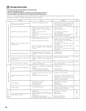
... function • Set to a suitable position. 63 button. • Volume control set 's power, then ventilate it well to cool it down. Have you operated the receiver according to on. 49 • Ground wire of turntable not connected • Connect securely. 7 Humming noise produced when Record is on. • Switch off the...
... function • Set to a suitable position. 63 button. • Volume control set 's power, then ventilate it well to cool it down. Have you operated the receiver according to on. 49 • Ground wire of turntable not connected • Connect securely. 7 Humming noise produced when Record is on. • Switch off the...
Owners Manual
Page 97
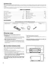
... 1 Speaker Configuration corresponding sizes (SMALL for regular speakers, LARGE for fullsize, full-range) to be output from the monitor output terminal. AUTO FM stations are received automatically and stored in order to obtain optimum effects. 4 Crossover Frequency Set the frequency (Hz) below which the audio signals are produced from the speakers...
... 1 Speaker Configuration corresponding sizes (SMALL for regular speakers, LARGE for fullsize, full-range) to be output from the monitor output terminal. AUTO FM stations are received automatically and stored in order to obtain optimum effects. 4 Crossover Frequency Set the frequency (Hz) below which the audio signals are produced from the speakers...

Owners Manual
Page 101
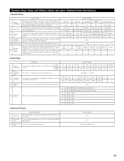
.../CR signal - 0.7Vp-p, 75 Ω/ohms Frequency response: DC ~ 100 MHz - +0, -3 dB 2 Tuner section [FM] (note: µV at 75 Ω/ohms, 0 dBf=1 x 10-15 W) [AM] Receiving Range: 87.50 MHz ~ 107.90 MHz 520 kHz ~ 1710 kHz Usable Sensitivity: 1.0 µV (11.2 dBf) 18 µV 50 dB Quieting Sensitivity: MONO 1.6 µV (15...
.../CR signal - 0.7Vp-p, 75 Ω/ohms Frequency response: DC ~ 100 MHz - +0, -3 dB 2 Tuner section [FM] (note: µV at 75 Ω/ohms, 0 dBf=1 x 10-15 W) [AM] Receiving Range: 87.50 MHz ~ 107.90 MHz 520 kHz ~ 1710 kHz Usable Sensitivity: 1.0 µV (11.2 dBf) 18 µV 50 dB Quieting Sensitivity: MONO 1.6 µV (15...

