Owner's Manual
Page 8
... 151 Replacing the Power Supply 152 I/O Panel 153 Removing the I/O Panel 154 Installing the I/O Panel 155 Processor Fan 155 Removing the Processor Fan/Heat Sink Assembly 156 Installing the Processor Fan/Heat Sink Assembly 157 Processor 158 Removing the Processor 158 Installing the Processor 159 Chassis... Fan 162 Removing the Chassis Fan 162 Replacing the Chassis Fan 163 System Board 164 Removing the System Board 164 Installing the System Board 165 Replacing the Computer Cover 166...
... 151 Replacing the Power Supply 152 I/O Panel 153 Removing the I/O Panel 154 Installing the I/O Panel 155 Processor Fan 155 Removing the Processor Fan/Heat Sink Assembly 156 Installing the Processor Fan/Heat Sink Assembly 157 Processor 158 Removing the Processor 158 Installing the Processor 159 Chassis... Fan 162 Removing the Chassis Fan 162 Replacing the Chassis Fan 163 System Board 164 Removing the System Board 164 Installing the System Board 165 Replacing the Computer Cover 166...
Owner's Manual
Page 78
... Computer" on page 15). TE S T T H E E L E C T R I V E R - Ensure that the sound is securely inserted into the headphone connector (see "Front View of your screen. Turn off nearby fans, fluorescent lights, or halogen lamps to eliminate distortion. See "Restoring Your Operating System" on page 92. Click or double-click the speaker icon in the...
... Computer" on page 15). TE S T T H E E L E C T R I V E R - Ensure that the sound is securely inserted into the headphone connector (see "Front View of your screen. Turn off nearby fans, fluorescent lights, or halogen lamps to eliminate distortion. See "Restoring Your Operating System" on page 92. Click or double-click the speaker icon in the...
Owner's Manual
Page 80
... Vista 1 Click Start → Control Panel→ Hardware and Sound→ Personalization→ Display Settings. 2 Adjust Resolution and Colors settings, as needed. 80 Solving Problems Fans, fluorescent lights, halogen lamps, and other electrical devices can cause the screen image to change or click the Display icon. 3 Try different settings for Color...
... Vista 1 Click Start → Control Panel→ Hardware and Sound→ Personalization→ Display Settings. 2 Adjust Resolution and Colors settings, as needed. 80 Solving Problems Fans, fluorescent lights, halogen lamps, and other electrical devices can cause the screen image to change or click the Display icon. 3 Try different settings for Color...

Owner's Manual
Page 84
.... The computer failed to complete the boot routine three consecutive times for loose cable connection. Replace CPU fan. D I S K E T T E D R I V E 0 S E E K F A I L U R E - See "Contacting Dell" on page 66. 84 Troubleshooting Tools See "Contacting Dell" on page 187 for assistance. CPU fan failure. Replace floppy disk and check for the same error. H A R D - System Messages NOTE: If the message you...
.... The computer failed to complete the boot routine three consecutive times for loose cable connection. Replace CPU fan. D I S K E T T E D R I V E 0 S E E K F A I L U R E - See "Contacting Dell" on page 66. 84 Troubleshooting Tools See "Contacting Dell" on page 187 for assistance. CPU fan failure. Replace floppy disk and check for the same error. H A R D - System Messages NOTE: If the message you...
Owner's Manual
Page 106
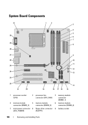
System Board Components 31 30 29 28 12 3 4 5 6 7 8 27 9 26 10 11 25 12 24 13 23 22 21 20 14 19 18 17 16 15 1 processor socket (CPU) 2 processor fan connector (CPU_FAN) 3 memory module connector (DIMM_1) 4 memory module 5 memory module 6 memory module connector (DIMM_2) connector (DIMM_3) connector (DIMM_4) 7 main power connector 8 floppy drive connector 9 battery socket (ATX_POWER) (FLOPPY) 106 Removing and Installing Parts
System Board Components 31 30 29 28 12 3 4 5 6 7 8 27 9 26 10 11 25 12 24 13 23 22 21 20 14 19 18 17 16 15 1 processor socket (CPU) 2 processor fan connector (CPU_FAN) 3 memory module connector (DIMM_1) 4 memory module 5 memory module 6 memory module connector (DIMM_2) connector (DIMM_3) connector (DIMM_4) 7 main power connector 8 floppy drive connector 9 battery socket (ATX_POWER) (FLOPPY) 106 Removing and Installing Parts

Owner's Manual
Page 137
... cable 6 screw holes in the floppy drive 10 Check all cable connections, and fold cables out of the way to avoid blocking airflow between the fan and cooling vents. 11 Replace the bezel (see "Replacing the Bezel" on page 125).
... cable 6 screw holes in the floppy drive 10 Check all cable connections, and fold cables out of the way to avoid blocking airflow between the fan and cooling vents. 11 Replace the bezel (see "Replacing the Bezel" on page 125).

Owner's Manual
Page 148
... 6 screw holes in the optical drive bay (2) 10 Check all cable connections, and fold cables out of the way to avoid blocking airflow between the fan and cooling vents. 11 Replace and tighten the two screws securing the optical drive. 12 Replace the bezel (see "Replacing the Bezel" on page 125...
... 6 screw holes in the optical drive bay (2) 10 Check all cable connections, and fold cables out of the way to avoid blocking airflow between the fan and cooling vents. 11 Replace and tighten the two screws securing the optical drive. 12 Replace the bezel (see "Replacing the Bezel" on page 125...
Owner's Manual
Page 155
...assembly, power supply, and other components may be very hot during normal operation. NOTE: The processor fan with the heatsink is one single unit. Do not try to remove the fan separately. Be sure that they have had sufficient time to cool before opening the cover. Processor... Verify that the computer works correctly by touching an unpainted metal surface on page 86). You can do so by running the Dell Diagnostics (see "Dell Diagnostics" on the computer chassis. NOTICE: To prevent static damage to components inside your computer, discharge static electricity from the electrical...
...assembly, power supply, and other components may be very hot during normal operation. NOTE: The processor fan with the heatsink is one single unit. Do not try to remove the fan separately. Be sure that they have had sufficient time to cool before opening the cover. Processor... Verify that the computer works correctly by touching an unpainted metal surface on page 86). You can do so by running the Dell Diagnostics (see "Dell Diagnostics" on the computer chassis. NOTICE: To prevent static damage to components inside your computer, discharge static electricity from the electrical...

Owner's Manual
Page 156
..."Before You Begin" on page 101. 2 Remove the computer cover (see "Removing the Computer Cover" on page 103). 3 Disconnect the processor fan cable from the system board (see "System Board Components" on page 106). 4 Carefully move away any cables that it has had sufficient time to...routed over the processor fan/heat sink assembly. 5 Loosen the four captive screws securing the processor fan/heat sink assembly and lift it straight up. Removing the Processor Fan/Heat Sink Assembly NOTICE: Do not touch the fan blades when you touch it. 1 2 1 captive screws (4) 2 processor fan/heat sink assembly ...
..."Before You Begin" on page 101. 2 Remove the computer cover (see "Removing the Computer Cover" on page 103). 3 Disconnect the processor fan cable from the system board (see "System Board Components" on page 106). 4 Carefully move away any cables that it has had sufficient time to...routed over the processor fan/heat sink assembly. 5 Loosen the four captive screws securing the processor fan/heat sink assembly and lift it straight up. Removing the Processor Fan/Heat Sink Assembly NOTICE: Do not touch the fan blades when you touch it. 1 2 1 captive screws (4) 2 processor fan/heat sink assembly ...

Owner's Manual
Page 157
... sink assembly cable to the four metal screw hole projections on page 106). Removing and Installing Parts 157 NOTE: The processor fan/heat sink assembly in your computer may vary from the one shown in the illustration above. 2 Tighten the four captive screws. NOTE: Ensure... that run between the system board and the fan. 1 Align the captive screws on the processor fan/heat sink assembly to the system board (see "System Board Components" on the system board. 1 2 1 captive screws (4) 2 processor...
... sink assembly cable to the four metal screw hole projections on page 106). Removing and Installing Parts 157 NOTE: The processor fan/heat sink assembly in your computer may vary from the one shown in the illustration above. 2 Tighten the four captive screws. NOTE: Ensure... that run between the system board and the fan. 1 Align the captive screws on the processor fan/heat sink assembly to the system board (see "System Board Components" on the system board. 1 2 1 captive screws (4) 2 processor...

Owner's Manual
Page 158
...). Processor CAUTION: Before you begin any of the release lever, then push down and out to cool before you touch it. 3 Remove the processor fan/heat sink assembly from the tab that it has had sufficient time to release it . 158 Removing and Installing Parts Be sure that secures it... from the computer (see "Removing the Processor Fan/Heat Sink Assembly" on page 156). 4 Replace the computer cover (see "Replacing the Computer Cover" on page 166). 5 Connect your finger upon the hook ...
...). Processor CAUTION: Before you begin any of the release lever, then push down and out to cool before you touch it. 3 Remove the processor fan/heat sink assembly from the tab that it has had sufficient time to release it . 158 Removing and Installing Parts Be sure that secures it... from the computer (see "Removing the Processor Fan/Heat Sink Assembly" on page 156). 4 Replace the computer cover (see "Replacing the Computer Cover" on page 166). 5 Connect your finger upon the hook ...

Owner's Manual
Page 161
...-1 indicator 3 processor 6 release lever 9 rear alignment notch 9 Clean the thermal grease from the bottom of the processor. 11 Install the processor fan/heat sink assembly (see "Replacing the Computer Cover" on page 157). New thermal grease is critical for optimal processor operation. 10 Apply the new... thermal grease to the top of the heat sink. NOTICE: Ensure that you apply new thermal grease. NOTICE: Ensure that the processor fan/heat sink assembly is a requirement for ensuring adequate thermal bonding, which is correctly seated and secure. 12 Replace the computer cover (see...
...-1 indicator 3 processor 6 release lever 9 rear alignment notch 9 Clean the thermal grease from the bottom of the processor. 11 Install the processor fan/heat sink assembly (see "Replacing the Computer Cover" on page 157). New thermal grease is critical for optimal processor operation. 10 Apply the new... thermal grease to the top of the heat sink. NOTICE: Ensure that you apply new thermal grease. NOTICE: Ensure that the processor fan/heat sink assembly is a requirement for ensuring adequate thermal bonding, which is correctly seated and secure. 12 Replace the computer cover (see...
Owner's Manual
Page 162
...your body before you touch any of your computer, discharge static electricity from the electrical outlet before you touch them. This could damage the fan. 1 Follow the procedures in the Product Information Guide. Be sure that they have had sufficient time to components inside your computer's electronic ...opening the cover. CAUTION: The heat sink assembly, power supply, and other components may be very hot during normal operation. Chassis Fan CAUTION: Before you begin any of the procedures in this section, follow the safety instructions in "Before You Begin" on the computer chassis....
...your body before you touch any of your computer, discharge static electricity from the electrical outlet before you touch them. This could damage the fan. 1 Follow the procedures in the Product Information Guide. Be sure that they have had sufficient time to components inside your computer's electronic ...opening the cover. CAUTION: The heat sink assembly, power supply, and other components may be very hot during normal operation. Chassis Fan CAUTION: Before you begin any of the procedures in this section, follow the safety instructions in "Before You Begin" on the computer chassis....

Owner's Manual
Page 163
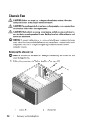
Replacing the Chassis Fan 1 Follow the procedures in place towards the front of the computer. 4 Tighten the four screws to secure the chassis fan. 2 Remove the computer cover (see "Removing the Computer Cover" on page 103). 3 Slide the chassis fan in "Before You Begin" on page 101. 1 2 1 screws (4) 2 chassis fan 2 Remove the computer cover (see "Removing the Computer Cover" on page 103). 3 Remove the four screws securing the chassis fan. 4 Slide the chassis fan towards the back of the computer and lift it up. Removing and Installing Parts 163
Replacing the Chassis Fan 1 Follow the procedures in place towards the front of the computer. 4 Tighten the four screws to secure the chassis fan. 2 Remove the computer cover (see "Removing the Computer Cover" on page 103). 3 Slide the chassis fan in "Before You Begin" on page 101. 1 2 1 screws (4) 2 chassis fan 2 Remove the computer cover (see "Removing the Computer Cover" on page 103). 3 Remove the four screws securing the chassis fan. 4 Slide the chassis fan towards the back of the computer and lift it up. Removing and Installing Parts 163
Owner's Manual
Page 164
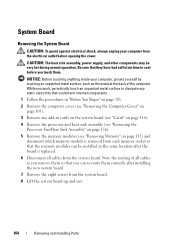
...). 3 Remove any add-in cards on the system board (see "Cards" on page 116). 4 Remove the processor and heat sink assembly (see "Removing the Processor Fan/Heat Sink Assembly" on page 156). 5 Remove the memory modules (see "Removing Memory" on page 115) and document which memory module is replaced. 6 Disconnect all...
...). 3 Remove any add-in cards on the system board (see "Cards" on page 116). 4 Remove the processor and heat sink assembly (see "Removing the Processor Fan/Heat Sink Assembly" on page 156). 5 Remove the memory modules (see "Removing Memory" on page 115) and document which memory module is replaced. 6 Disconnect all...

Owner's Manual
Page 171
...) or Media Card Reader (optional) Connectors External connectors: Video Network adapter USB Audio System board connectors: Serial ATA Internal USB device Floppy drive Processor fan Chassis fan PCI 2.3 PCI Express x1 PCI Express x16 Front panel control 15-hole connector RJ-45 connector four front-panel and four back-panel USB 2.0compliant...
...) or Media Card Reader (optional) Connectors External connectors: Video Network adapter USB Audio System board connectors: Serial ATA Internal USB device Floppy drive Processor fan Chassis fan PCI 2.3 PCI Express x1 PCI Express x16 Front panel control 15-hole connector RJ-45 connector four front-panel and four back-panel USB 2.0compliant...


