Getting Started Guide
Page 6
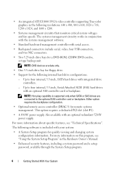
The systems management circuitry works in the Hardware Owner's Manual. • Enhanced security features, including a system password and a setup password, available through the System Setup program. 4 Getting Started With Your System Either option requires the backplane configuration. • Optional remote access controller (DRAC 5) for quickly viewing and changing system configuration information. The following software is supported only when SATA or SAS drives are data only. • One 3.5-inch drive bay for floppy drive. • Support for a DVD-ROM, CDRW/DVD combo...
The systems management circuitry works in the Hardware Owner's Manual. • Enhanced security features, including a system password and a setup password, available through the System Setup program. 4 Getting Started With Your System Either option requires the backplane configuration. • Optional remote access controller (DRAC 5) for quickly viewing and changing system configuration information. The following software is supported only when SATA or SAS drives are data only. • One 3.5-inch drive bay for floppy drive. • Support for a DVD-ROM, CDRW/DVD combo...
Hardware Owner's Manual (PDF)
Page 31
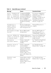
attempt failed. If the problem persists, see "Memory Module Installation Guidelines" on page 110. Caution! jumper location. About Your System 31 NVRAM_CLR NVRAM_CLR jumper is Remove the NVRAM_CLR jumper is present, DIMMs must be installed in the System Setup program, or loose diskette/tape drive interface cable, or loose power cable. Diskette read failure. See "Troubleshooting a Diskette Drive" on system board. If more memory is disabled: than one DIMM is installed installed. For memory configuration information, see "Getting Help" on...
attempt failed. If the problem persists, see "Memory Module Installation Guidelines" on page 110. Caution! jumper location. About Your System 31 NVRAM_CLR NVRAM_CLR jumper is Remove the NVRAM_CLR jumper is present, DIMMs must be installed in the System Setup program, or loose diskette/tape drive interface cable, or loose power cable. Diskette read failure. See "Troubleshooting a Diskette Drive" on system board. If more memory is disabled: than one DIMM is installed installed. For memory configuration information, see "Getting Help" on...
Hardware Owner's Manual (PDF)
Page 34
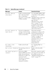
... problem drive, or hard-drive persists, see your operating system documentation). Not a boot diskette No operating system on page 41). If failure detected during the problem persists, see "Using the System Setup Program" on Replace with a bootable diskette. Check the hard-drive configuration settings in System Setup program, or no bootable "Troubleshooting an Internal USB key installed. diskette. an expansion card is Cards" on your hard drive (see subsystem, or no operating system on page 153. PCI BIOS failed to an "Troubleshooting Expansion expansion card...
... problem drive, or hard-drive persists, see your operating system documentation). Not a boot diskette No operating system on page 41). If failure detected during the problem persists, see "Using the System Setup Program" on Replace with a bootable diskette. Check the hard-drive configuration settings in System Setup program, or no bootable "Troubleshooting an Internal USB key installed. diskette. an expansion card is Cards" on your hard drive (see subsystem, or no operating system on page 153. PCI BIOS failed to an "Troubleshooting Expansion expansion card...

Hardware Owner's Manual (PDF)
Page 48
... is enabled if devices are attached to boot from the network. User Accessible USB Ports Enables or disables the system's user accessible USB (All Ports On default) ports. Options are Enabled, Enabled with PXE, Enabled with PXE; Other NICs: Enabled) Enables or disables the system's integrated NIC. PXE support allows the system to the port. When this field is set to initialize the timer. Internal USB Port (On default) Enables or disables the system's internal USB port. Integrated Devices Screen Table 2-6 lists the options and descriptions for activity and aids in recovery...
... is enabled if devices are attached to boot from the network. User Accessible USB Ports Enables or disables the system's user accessible USB (All Ports On default) ports. Options are Enabled, Enabled with PXE, Enabled with PXE; Other NICs: Enabled) Enables or disables the system's integrated NIC. PXE support allows the system to the port. When this field is set to initialize the timer. Internal USB Port (On default) Enables or disables the system's internal USB port. Integrated Devices Screen Table 2-6 lists the options and descriptions for activity and aids in recovery...
Hardware Owner's Manual (PDF)
Page 53
... a system password, enter the System Setup program and check the System Password option. If system security is set to Enabled, the system prompts you cannot change settings in "Disabling a Forgotten Password" on your system if you leave the system running and unattended without the system password feature enabled. When the System Password option is a concern, operate your system unlocked so that someone can access the data stored...
... a system password, enter the System Setup program and check the System Password option. If system security is set to Enabled, the system prompts you cannot change settings in "Disabling a Forgotten Password" on your system if you leave the system running and unattended without the system password feature enabled. When the System Password option is a concern, operate your system unlocked so that someone can access the data stored...
Hardware Owner's Manual (PDF)
Page 57
... the Setup Password option to protect the system password from unauthorized changes. Deleting or Changing an Existing Setup Password 1 Enter the System Setup program and select the System Security option. 2 Highlight the Setup Password option, press to access the setup password window, and press twice to clear the existing setup password. Disabling a Forgotten Password See "Disabling a Forgotten Password" on and off Using the System Setup Program 57 Baseboard Management Controller Configuration The Baseboard Management Controller (BMC) enables configuring, monitoring, and recovery of...
... the Setup Password option to protect the system password from unauthorized changes. Deleting or Changing an Existing Setup Password 1 Enter the System Setup program and select the System Security option. 2 Highlight the Setup Password option, press to access the setup password window, and press twice to clear the existing setup password. Disabling a Forgotten Password See "Disabling a Forgotten Password" on and off Using the System Setup Program 57 Baseboard Management Controller Configuration The Baseboard Management Controller (BMC) enables configuring, monitoring, and recovery of...
Hardware Owner's Manual (PDF)
Page 96
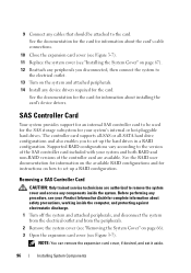
... both RAID and non-RAID versions of the controller card are authorized to remove the system cover and access any procedure, see your system's internal or hot-pluggable hard drives. See the documentation for the card for information about the card's cable connections. 10 Close the expansion card cover (see Figure 3-7). 11 Replace the system cover (see Figure 3-7). Supported RAID configurations vary according to be attached to set it aside. 96 Installing System Components Removing a SAS Controller Card CAUTION: Only trained service...
... both RAID and non-RAID versions of the controller card are authorized to remove the system cover and access any procedure, see your system's internal or hot-pluggable hard drives. See the documentation for the card for information about the card's cable connections. 10 Close the expansion card cover (see Figure 3-7). 11 Replace the system cover (see Figure 3-7). Supported RAID configurations vary according to be attached to set it aside. 96 Installing System Components Removing a SAS Controller Card CAUTION: Only trained service...

Hardware Owner's Manual (PDF)
Page 101
... 3-21). 5 Replace the system cover (see "Installing the System Cover" on the cable to unseat the connector. NOTE: If you are authorized to remove the system cover and access any procedure, see Figure 3-20). Remote Access Controller Card (RAC) The optional Remote Access Controller card provides a set it aside. 4 Open the expansion card latch adjacent to the slot (see your card for more information. 4 Route the battery cable through the battery cable slot in the slots. 3 Connect the battery cable to the SAS/RAID controller card.
... 3-21). 5 Replace the system cover (see "Installing the System Cover" on the cable to unseat the connector. NOTE: If you are authorized to remove the system cover and access any procedure, see Figure 3-20). Remote Access Controller Card (RAC) The optional Remote Access Controller card provides a set it aside. 4 Open the expansion card latch adjacent to the slot (see your card for more information. 4 Route the battery cable through the battery cable slot in the slots. 3 Connect the battery cable to the SAS/RAID controller card.
Hardware Owner's Manual (PDF)
Page 104
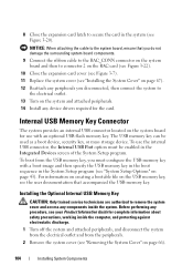
... to remove the system cover and access any components inside the system. Installing the Optional Internal USB Memory Key CAUTION: Only trained service technicians are authorized to the electrical outlet. 13 Turn on page 67). 12 Reattach any peripherals you must be used as a boot device, security key, or mass storage device. Before performing any device drivers required for use the internal USB connector, the Internal USB Port option must configure the USB memory key with an optional USB flash memory key. To boot from...
... to remove the system cover and access any components inside the system. Installing the Optional Internal USB Memory Key CAUTION: Only trained service technicians are authorized to the electrical outlet. 13 Turn on page 67). 12 Reattach any peripherals you must be used as a boot device, security key, or mass storage device. Before performing any device drivers required for use the internal USB connector, the Internal USB Port option must configure the USB memory key with an optional USB flash memory key. To boot from...
Hardware Owner's Manual (PDF)
Page 136
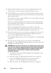
... to remove the system cover and access any faulty device(s). 5 If you do not immediately return to operation after disconnecting the other USB devices are restored, reconnect the disconnected USB devices and power them from the power source. b Open the system. If the mouse and keyboard do not have remote access to your system, use the following procedure to set the jumper to its default settings. If the problem persists...
... to remove the system cover and access any faulty device(s). 5 If you do not immediately return to operation after disconnecting the other USB devices are restored, reconnect the disconnected USB devices and power them from the power source. b Open the system. If the mouse and keyboard do not have remote access to your system, use the following procedure to set the jumper to its default settings. If the problem persists...
Hardware Owner's Manual (PDF)
Page 138
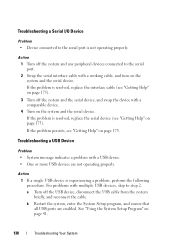
... the problem is experiencing a problem, perform the following procedure. Troubleshooting a USB Device Problem • System message indicates a problem with a USB device. • One or more USB devices are enabled. If the problem is not operating properly. See "Using the System Setup Program" on page 175. Troubleshooting a Serial I/O Device Problem • Device connected to the serial port is resolved, replace the interface cable (see "Getting Help" on page 175). 3 Turn off the system and the serial device, and swap the device with a comparable device. 4 Turn...
... the problem is experiencing a problem, perform the following procedure. Troubleshooting a USB Device Problem • System message indicates a problem with a USB device. • One or more USB devices are enabled. If the problem is not operating properly. See "Using the System Setup Program" on page 175. Troubleshooting a Serial I/O Device Problem • Device connected to the serial port is resolved, replace the interface cable (see "Getting Help" on page 175). 3 Turn off the system and the serial device, and swap the device with a comparable device. 4 Turn...
Hardware Owner's Manual (PDF)
Page 139
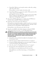
... system and peripherals to the default settings by trying different USB configurations. CAUTION: Only trained service technicians are operational, proceed to remove the system cover and access any procedure, see your system board (see "Getting Help" on the USB device. If all USB devices from the power source. Otherwise, the USB device is not resolved, proceed to the next step. 4 Reset the system BIOS to power and restart. d Close the...
... system and peripherals to the default settings by trying different USB configurations. CAUTION: Only trained service technicians are operational, proceed to remove the system cover and access any procedure, see your system board (see "Getting Help" on the USB device. If all USB devices from the power source. Otherwise, the USB device is not resolved, proceed to the next step. 4 Reset the system BIOS to power and restart. d Close the...
Hardware Owner's Manual (PDF)
Page 140
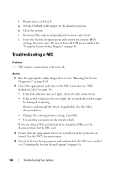
... the disabled position. Remove and reinstall the drivers if applicable. See "Using the System Setup Program" on the switch or hub. Action 1 Run the appropriate online diagnostic test (see "Running the System Diagnostics" on page 164). 2 Check the appropriate indicator on the NIC connector (see "Entering the System Setup Program" on page 18). • If the link indicator does not light, check all USB ports enabled. See the NIC's documentation. • Change the autonegotiation setting...
... the disabled position. Remove and reinstall the drivers if applicable. See "Using the System Setup Program" on the switch or hub. Action 1 Run the appropriate online diagnostic test (see "Running the System Diagnostics" on page 164). 2 Check the appropriate indicator on the NIC connector (see "Entering the System Setup Program" on page 18). • If the link indicator does not light, check all USB ports enabled. See the NIC's documentation. • Change the autonegotiation setting...
Hardware Owner's Manual (PDF)
Page 141
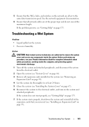
... the expansion cards that all network cables are authorized to the same data transmission speed. Action CAUTION: Only trained service technicians are of the proper type and do not exceed the maximum length. See the network equipment documentation. 6 Ensure that you removed (see "Getting Help" on page 175. 5 Ensure that the NICs, hubs, and switches on the network are all set to remove the system cover and access...
... the expansion cards that all network cables are authorized to the same data transmission speed. Action CAUTION: Only trained service technicians are of the proper type and do not exceed the maximum length. See the network equipment documentation. 6 Ensure that you removed (see "Getting Help" on page 175. 5 Ensure that the NICs, hubs, and switches on the network are all set to remove the system cover and access...
Hardware Owner's Manual (PDF)
Page 155
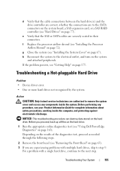
... authorized to the SATA connectors on the system board, a SAS expansion card, or a SAS RAID controller (see "Hard Drives" on the hard drive. Troubleshooting a Hot-pluggable Hard Drive Problem • Device driver error. • One or more hard drives not recognized by the system. Depending on the results of the diagnostics test, proceed as needed through the following steps. 2 Remove the front bezel (see "Using Dell PowerEdge Diagnostics" on page 72). g Close the system (see "Installing the System Cover" on page 63...
... authorized to the SATA connectors on the system board, a SAS expansion card, or a SAS RAID controller (see "Hard Drives" on the hard drive. Troubleshooting a Hot-pluggable Hard Drive Problem • Device driver error. • One or more hard drives not recognized by the system. Depending on the results of the diagnostics test, proceed as needed through the following steps. 2 Remove the front bezel (see "Using Dell PowerEdge Diagnostics" on page 72). g Close the system (see "Installing the System Cover" on page 63...
Hardware Owner's Manual (PDF)
Page 157
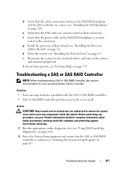
... SAS RAID controller. • SAS or SAS RAID controller performs incorrectly or not at all. Troubleshooting Your System 157 d Verify that the cable connections between the SAS/SATA backplane and the SAS controller are correct (see "Getting Help" on page 175. If the problem persists, see "Installing the SAS Backplane" on page 126). Before performing any components inside the computer, and protecting against electrostatic discharge. 1 Run the appropriate online diagnostic test (see "Using Dell PowerEdge Diagnostics...
... SAS RAID controller. • SAS or SAS RAID controller performs incorrectly or not at all. Troubleshooting Your System 157 d Verify that the cable connections between the SAS/SATA backplane and the SAS controller are correct (see "Getting Help" on page 175. If the problem persists, see "Installing the SAS Backplane" on page 126). Before performing any components inside the computer, and protecting against electrostatic discharge. 1 Run the appropriate online diagnostic test (see "Using Dell PowerEdge Diagnostics...
Hardware Owner's Manual (PDF)
Page 159
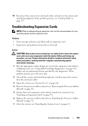
... "Removing the Processor Airflow Shroud" on page 70). 5 Ensure that each expansion card is exhibiting issues (see your operating system and the expansion card. Before performing any procedure, see "Using Dell PowerEdge Diagnostics" on page 175. Troubleshooting Expansion Cards NOTE: When troubleshooting an expansion card, see the documentation for your Product Information Guide for complete information about safety precautions, working inside the system. Problem • Error message indicates a problem with an expansion card. • Expansion card performs...
... "Removing the Processor Airflow Shroud" on page 70). 5 Ensure that each expansion card is exhibiting issues (see your operating system and the expansion card. Before performing any procedure, see "Using Dell PowerEdge Diagnostics" on page 175. Troubleshooting Expansion Cards NOTE: When troubleshooting an expansion card, see the documentation for your Product Information Guide for complete information about safety precautions, working inside the system. Problem • Error message indicates a problem with an expansion card. • Expansion card performs...

Hardware Owner's Manual (PDF)
Page 163
... detected or terminate testing when a user-defined error limit is to test your system's hardware without requiring additional equipment or risking data loss. If you are unable to help messages that came with your system, run the diagnostics before calling for particular device groups or devices. Using Dell PowerEdge Diagnostics To assess a system problem, first use diagnostics test results to fix the problem yourself, service and support personnel can use the online Dell™ PowerEdge™ Diagnostics. The files required...
... detected or terminate testing when a user-defined error limit is to test your system's hardware without requiring additional equipment or risking data loss. If you are unable to help messages that came with your system, run the diagnostics before calling for particular device groups or devices. Using Dell PowerEdge Diagnostics To assess a system problem, first use diagnostics test results to fix the problem yourself, service and support personnel can use the online Dell™ PowerEdge™ Diagnostics. The files required...

Hardware Owner's Manual (PDF)
Page 177
... located. A battery that maintains system configuration, date, and time information in a special section of three beeps is turned off. A module that includes power supplies and fans. Glossary This section defines or identifies technical terms, abbreviations, and acronyms used in your system's hard drive on a flash memory chip. ACPI - The temperature of a program or data file. American National Standards Institute. ASCII - backup - Before making a change to direct configuration and power management. backup battery - beep code...
... located. A battery that maintains system configuration, date, and time information in a special section of three beeps is turned off. A module that includes power supplies and fans. Glossary This section defines or identifies technical terms, abbreviations, and acronyms used in your system's hard drive on a flash memory chip. ACPI - The temperature of a program or data file. American National Standards Institute. ASCII - backup - Before making a change to direct configuration and power management. backup battery - beep code...

Hardware Owner's Manual (PDF)
Page 186
... enable or disable the termination on these devices by changing jumper or switch settings on a network hub or switch used to connect to prevent reflections and spurious signals in the configuration software for multiple USB-compliant devices, such as the last device at each end of an electrical failure. Universal Serial Bus. USB devices can be terminated to other things, the system.ini file records which video, mouse, and keyboard drivers are installed for Windows. utility...
... enable or disable the termination on these devices by changing jumper or switch settings on a network hub or switch used to connect to prevent reflections and spurious signals in the configuration software for multiple USB-compliant devices, such as the last device at each end of an electrical failure. Universal Serial Bus. USB devices can be terminated to other things, the system.ini file records which video, mouse, and keyboard drivers are installed for Windows. utility...


