
Getting Started Guide
Page 9
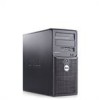
Next, plug the other end of the power cable into a grounded electrical outlet or a separate power source such as an uninterrupted power supply (UPS) or a power distribution unit (PDU). Getting Started With Your System 7 Connect the System to Power Connect the system's power cable to the system. Adjust the monitor's controls until the displayed image is satisfactory. The power indicators should light. Turn on the System and Monitor Press the power button on the system and the monitor.
Next, plug the other end of the power cable into a grounded electrical outlet or a separate power source such as an uninterrupted power supply (UPS) or a power distribution unit (PDU). Getting Started With Your System 7 Connect the System to Power Connect the system's power cable to the system. Adjust the monitor's controls until the displayed image is satisfactory. The power indicators should light. Turn on the System and Monitor Press the power button on the system and the monitor.
Getting Started Guide
Page 12
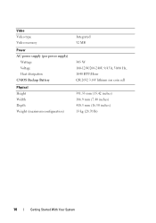
Video Video type Video memory Power AC power supply (per power supply) Wattage Voltage Heat dissipation CMOS Backup Battery Physical Height Width Depth Weight (maximum configuration) Integrated 32 MB 305 W 100-120V/200-240V, 9/4.5A, 50/60 Hz, 1040 BTU/Hour CR 2032 3.0-V lithium ion coin cell 391.55 mm (15.42 inches) 186.9 mm (7.40 inches) 418.5 mm (16.50 inches) 13 kg (28.70 lb) 10 Getting Started With Your System
Video Video type Video memory Power AC power supply (per power supply) Wattage Voltage Heat dissipation CMOS Backup Battery Physical Height Width Depth Weight (maximum configuration) Integrated 32 MB 305 W 100-120V/200-240V, 9/4.5A, 50/60 Hz, 1040 BTU/Hour CR 2032 3.0-V lithium ion coin cell 391.55 mm (15.42 inches) 186.9 mm (7.40 inches) 418.5 mm (16.50 inches) 13 kg (28.70 lb) 10 Getting Started With Your System

Hardware Owner's Manual (PDF)
Page 3
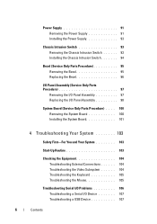
Contents 1 About Your System 11 Other Information You May Need 11 Accessing System Features During Startup 12 Front-Panel Features and Indicators 13 Back-Panel Features and Indicators 15 Connecting External Devices 16 NIC Indicator Codes 16 Power Supply Indicators 17 Diagnostic Lights 18 System Messages 20 Warning Messages 29 Diagnostics Messages 29 Alert Messages 30 2 Using the System Setup Program 31 Entering the System Setup Program 31 Responding to Error Messages 31 Using the System Setup Program 32 Exiting the System Setup Program 33 Contents 3
Contents 1 About Your System 11 Other Information You May Need 11 Accessing System Features During Startup 12 Front-Panel Features and Indicators 13 Back-Panel Features and Indicators 15 Connecting External Devices 16 NIC Indicator Codes 16 Power Supply Indicators 17 Diagnostic Lights 18 System Messages 20 Warning Messages 29 Diagnostics Messages 29 Alert Messages 30 2 Using the System Setup Program 31 Entering the System Setup Program 31 Responding to Error Messages 31 Using the System Setup Program 32 Exiting the System Setup Program 33 Contents 3
Hardware Owner's Manual (PDF)
Page 6
... Removing the Power Supply 91 Installing the Power Supply 93 Chassis Intrusion Switch 93 Removing the Chassis Intrusion Switch 93 Installing the Chassis Intrusion Switch 94 Bezel (Service Only Parts Procedure 95 Removing ...
... Removing the Power Supply 91 Installing the Power Supply 93 Chassis Intrusion Switch 93 Removing the Chassis Intrusion Switch 93 Installing the Chassis Intrusion Switch 94 Bezel (Service Only Parts Procedure 95 Removing ...
Hardware Owner's Manual (PDF)
Page 7
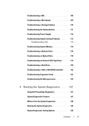
...108 Troubleshooting a Wet System 109 Troubleshooting a Damaged System 110 Troubleshooting the System Battery 111 Troubleshooting Power Supply 112 Troubleshooting System Cooling Problems 113 Troubleshooting a Fan 113 Troubleshooting System Memory 114 Troubleshooting a... . . . 122 Troubleshooting Expansion Cards 123 Troubleshooting the Microprocessor 125 5 Running the System Diagnostics 127 Using Dell PowerEdge Diagnostics 127 System Diagnostics Features 127 When to Use the System Diagnostics 128 Running the System Diagnostics 128 System Diagnostics Testing Options 128 Contents 7
...108 Troubleshooting a Wet System 109 Troubleshooting a Damaged System 110 Troubleshooting the System Battery 111 Troubleshooting Power Supply 112 Troubleshooting System Cooling Problems 113 Troubleshooting a Fan 113 Troubleshooting System Memory 114 Troubleshooting a... . . . 122 Troubleshooting Expansion Cards 123 Troubleshooting the Microprocessor 125 5 Running the System Diagnostics 127 Using Dell PowerEdge Diagnostics 127 System Diagnostics Features 127 When to Use the System Diagnostics 128 Running the System Diagnostics 128 System Diagnostics Testing Options 128 Contents 7

Hardware Owner's Manual (PDF)
Page 14
...system is pressed. See "Diagnostic Lights" on . There is in a low power state. Blinking green - Holds an optional optical or tape backup unit drive. Front-Panel Components (continued) Item Component Icon 2 power button 3 power light 4 flex bay 5 lower 5.25-inch drive bay 6 upper 5.25-inch... drive bay Description The power button controls the DC power supply output to the system. Holds an optical drive. 14 ...
...system is pressed. See "Diagnostic Lights" on . There is in a low power state. Blinking green - Holds an optional optical or tape backup unit drive. Front-Panel Components (continued) Item Component Icon 2 power button 3 power light 4 flex bay 5 lower 5.25-inch drive bay 6 upper 5.25-inch... drive bay Description The power button controls the DC power supply output to the system. Holds an optical drive. 14 ...

Hardware Owner's Manual (PDF)
Page 15
Back-Panel Features and Indicators 1 2 1 voltage selection switch 3 USB connectors (5) 5 video connector 7 I/O expansion-card slots (4) 3 4 5 6 7 2 power connector 4 NIC connector 6 serial connector About Your System 15 Figure 1-2. Back-Panel Features and Indicators Figure 1-2 shows the controls, indicators, and connectors located on the system's back panel.
Back-Panel Features and Indicators 1 2 1 voltage selection switch 3 USB connectors (5) 5 video connector 7 I/O expansion-card slots (4) 3 4 5 6 7 2 power connector 4 NIC connector 6 serial connector About Your System 15 Figure 1-2. Back-Panel Features and Indicators Figure 1-2 shows the controls, indicators, and connectors located on the system's back panel.

Hardware Owner's Manual (PDF)
Page 17
...1-4. Table 1-4. About Your System 17 See "Using the System Setup Program" on page 31. 1000-Mbps connection 100-Mbps connection 10-Mbps connection Power Supply Indicators The voltage selection switch on page 31. Indicates that the activity indicator is off , the NIC is not connected to : 110 ...V 115 220 V 230 For information on system power requirements, see "Technical Specifications" in your power source is being sent or received. When off at the same time that the switch is disabled in the System Setup ...
...1-4. Table 1-4. About Your System 17 See "Using the System Setup Program" on page 31. 1000-Mbps connection 100-Mbps connection 10-Mbps connection Power Supply Indicators The voltage selection switch on page 31. Indicates that the activity indicator is off , the NIC is not connected to : 110 ...V 115 220 V 230 For information on system power requirements, see "Technical Specifications" in your power source is being sent or received. When off at the same time that the switch is disabled in the System Setup ...

Hardware Owner's Manual (PDF)
Page 18
..." on page 114. See "Troubleshooting System Memory" on page 137. system is in a normal Information only. NOTE: If the power LEDs blink amber, there is on the system front panel display error codes during system startup. Table 1-5 lists the causes and possible... occurred. Possible processor failure. Memory failure. The system is off condition or a electrical outlet and press the possible pre-BIOS failure power button. BIOS checksum failure detected; The diagnostic lights are not lit after POST. a non-highlighted circle indicates the light is in ...
..." on page 114. See "Troubleshooting System Memory" on page 137. system is in a normal Information only. NOTE: If the power LEDs blink amber, there is on the system front panel display error codes during system startup. Table 1-5 lists the causes and possible... occurred. Possible processor failure. Memory failure. The system is off condition or a electrical outlet and press the possible pre-BIOS failure power button. BIOS checksum failure detected; The diagnostic lights are not lit after POST. a non-highlighted circle indicates the light is in ...

Hardware Owner's Manual (PDF)
Page 30
Alert Messages Systems management software generates alert messages for drive, temperature, fan, and power conditions. For more information, see the systems management software documentation. 30 About Your System Alert messages include information, status, warning, and failure messages for your ...
Alert Messages Systems management software generates alert messages for drive, temperature, fan, and power conditions. For more information, see the systems management software documentation. 30 About Your System Alert messages include information, status, warning, and failure messages for your ...

Hardware Owner's Manual (PDF)
Page 36
... and will be unchoosable. When the SAS Card is installed in the processor. CPU Information Screen Option 64-Bit Core Speed Bus Speed Demand-Based Power Management Processor 1 ID Level2 Cache Number of cores in the system, the SATA Configuration screen changes. When set to the operating system. This option does...
... and will be unchoosable. When the SAS Card is installed in the processor. CPU Information Screen Option 64-Bit Core Speed Bus Speed Demand-Based Power Management Processor 1 ID Level2 Cache Number of cores in the system, the SATA Configuration screen changes. When set to the operating system. This option does...
Hardware Owner's Manual (PDF)
Page 38
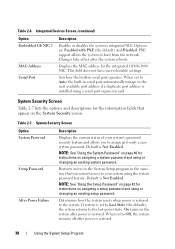
...System Security Screen Table 2-7 lists the options and descriptions for the integrated 10/100/1000 NIC. Determines how the system reacts when power is set to your system's password security feature and allows you restrict access to Off, the system remains off after the system ... Password" on page 40 for instructions on the System Security screen. Table 2-6. System Security Screen Option System Password Setup Password After Power Failure Description Displays the current status of your system using or changing an existing setup password. If system is restored to boot from...
...System Security Screen Table 2-7 lists the options and descriptions for the integrated 10/100/1000 NIC. Determines how the system reacts when power is set to your system's password security feature and allows you restrict access to Off, the system remains off after the system ... Password" on page 40 for instructions on the System Security screen. Table 2-6. System Security Screen Option System Password Setup Password After Power Failure Description Displays the current status of your system using or changing an existing setup password. If system is restored to boot from...

Hardware Owner's Manual (PDF)
Page 45
...; Optical and tape drives • Hard drives • Expansion cards • SAS controller card • Memory • Microprocessor • Cooling fans • System battery • Power supply • Chassis intrusion switch • Bezel • I/O panel • System board Recommended Tools You may need the following items to perform the procedures in...
...; Optical and tape drives • Hard drives • Expansion cards • SAS controller card • Memory • Microprocessor • Cooling fans • System battery • Power supply • Chassis intrusion switch • Bezel • I/O panel • System board Recommended Tools You may need the following items to perform the procedures in...

Hardware Owner's Manual (PDF)
Page 46
Drive bays in the front of the system. Inside the System 10 1 9 8 2 3 7 6 5 1 power supply 3 system board 5 3.5-inch drive bay 7 5.25-inch drive bays (2) 9 drive cage 4 2 heat sink and shroud assembly 4 hard drives (2) 6 tape backup unit 8 bezel sliding plate ...
Drive bays in the front of the system. Inside the System 10 1 9 8 2 3 7 6 5 1 power supply 3 system board 5 3.5-inch drive bay 7 5.25-inch drive bays (2) 9 drive cage 4 2 heat sink and shroud assembly 4 hard drives (2) 6 tape backup unit 8 bezel sliding plate ...

Hardware Owner's Manual (PDF)
Page 47
... against electrostatic discharge. 1 Turn off the system and attached peripherals, and disconnect the system from the electrical outlet. 2 Press the power button to the electrical outlet, and turn on its side as shown in Figure 3-2. 4 Open the system by sliding the cover ... intrusion detector, if enabled, causes the following message to the system board and internal peripherals through a single nonredundant power supply. Cover was previously opened. Power is required for complete information about safety precautions, working inside the system. Closing the System 1 Ensure that all ...
... against electrostatic discharge. 1 Turn off the system and attached peripherals, and disconnect the system from the electrical outlet. 2 Press the power button to the electrical outlet, and turn on its side as shown in Figure 3-2. 4 Open the system by sliding the cover ... intrusion detector, if enabled, causes the following message to the system board and internal peripherals through a single nonredundant power supply. Cover was previously opened. Power is required for complete information about safety precautions, working inside the system. Closing the System 1 Ensure that all ...

Hardware Owner's Manual (PDF)
Page 53
... Bezel" on page 49. If you are replacing the diskette drive, see "Installing a Diskette Drive" on page 54. 8 Replace the front drive bezel. 4 Disconnect the power and data cables from the diskette drive. See Figure 3-6. 6 Hold the lever in the direction of the bay. See Figure 3-6. 5 Slide the lever on front...
... Bezel" on page 49. If you are replacing the diskette drive, see "Installing a Diskette Drive" on page 54. 8 Replace the front drive bezel. 4 Disconnect the power and data cables from the diskette drive. See Figure 3-6. 6 Hold the lever in the direction of the bay. See Figure 3-6. 5 Slide the lever on front...

Hardware Owner's Manual (PDF)
Page 55
See Figure 3-8 and Figure 6-2. Installing System Components 55 Figure 3-7. Installing Diskette Drive Shoulder Screws 1 1 screws (4) 9 From the front of the chassis, slide the drive into the drive bay until the shoulder screws fit into their slots and snap securely into the sliding plate. 10 Connect the P7 power cable to the diskette drive connector (FLOPPY) on the system board. See Figure 3-8. 11 Connect the data cable from the drive to the drive.
See Figure 3-8 and Figure 6-2. Installing System Components 55 Figure 3-7. Installing Diskette Drive Shoulder Screws 1 1 screws (4) 9 From the front of the chassis, slide the drive into the drive bay until the shoulder screws fit into their slots and snap securely into the sliding plate. 10 Connect the P7 power cable to the diskette drive connector (FLOPPY) on the system board. See Figure 3-8. 11 Connect the data cable from the drive to the drive.
Hardware Owner's Manual (PDF)
Page 56
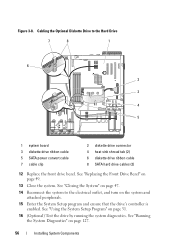
... the system diagnostics. See "Closing the System" on page 47. 14 Reconnect the system to the Hard Drive 7 8 1 6 2 3 4 5 1 system board 3 diskette drive ribbon cable 5 SATA power convert cable 7 cable clip 2 diskette drive connector 4 heat sink shroud tab (2) 6 diskette drive ribbon cable 8 SATA hard drive cables (2) 12 Replace the front drive bezel...
... the system diagnostics. See "Closing the System" on page 47. 14 Reconnect the system to the Hard Drive 7 8 1 6 2 3 4 5 1 system board 3 diskette drive ribbon cable 5 SATA power convert cable 7 cable clip 2 diskette drive connector 4 heat sink shroud tab (2) 6 diskette drive ribbon cable 8 SATA hard drive cables (2) 12 Replace the front drive bezel...

Hardware Owner's Manual (PDF)
Page 57
... the system. See "Removing the Front Drive Bezel" on page 47. 3 Remove the front drive bezel. See "Opening the System" on page 49. 4 Disconnect the power and data cables from the drive bay. In the lower 5.25-inch drive bay, you can install either an optical or a tape backup unit. Before...
... the system. See "Removing the Front Drive Bezel" on page 47. 3 Remove the front drive bezel. See "Opening the System" on page 49. 4 Disconnect the power and data cables from the drive bay. In the lower 5.25-inch drive bay, you can install either an optical or a tape backup unit. Before...

Hardware Owner's Manual (PDF)
Page 61
Installing Optical or Tape Drive Shoulder Screws 1 1 screws (3) 8 Gently slide the drive into place until you hear a click or feel the drive securely installed. 9 Attach the SCSI power cable (see Figure 3-12) or SATA power cable (see Figure 3-13) to the bottom row of holes and two to the drive. Figure 3-11. Ensure that cables are secured in their respective clips. 7 Remove the three shoulder screws from the insert, and attach one of them to the row of holes on the drive. Installing System Components 61 See Figure 3-11.
Installing Optical or Tape Drive Shoulder Screws 1 1 screws (3) 8 Gently slide the drive into place until you hear a click or feel the drive securely installed. 9 Attach the SCSI power cable (see Figure 3-12) or SATA power cable (see Figure 3-13) to the bottom row of holes and two to the drive. Figure 3-11. Ensure that cables are secured in their respective clips. 7 Remove the three shoulder screws from the insert, and attach one of them to the row of holes on the drive. Installing System Components 61 See Figure 3-11.


