Information Update
Page 1
...; Linux Enterprise Server 10 Service Pack 1 does not support internal SATA optical drives on systems with more than 4 GB of an issue with the adma mode disabled during and after installation because of system memory. A fix for this issue, you must be available in your system, its capacity must load the sata_nv driver with the sata_nv driver. Add the following text to the SATA controller is...
...; Linux Enterprise Server 10 Service Pack 1 does not support internal SATA optical drives on systems with more than 4 GB of an issue with the adma mode disabled during and after installation because of system memory. A fix for this issue, you must be available in your system, its capacity must load the sata_nv driver with the sata_nv driver. Add the following text to the SATA controller is...
Getting Started Guide
Page 5
... SATA controller or - NOTE: Use the System Setup program to a maximum of 8 GB DDR II SDRAM memory by installing 512-MB, 1-GB, or 2-GB unbuffered ECC memory modules in the four memory module sockets on the system board; Up to two internal 3.5-inch Serial-Attached SCSI (SAS) hard drives with an optional SAS RAID controller card: simple, spanned, striped (RAID 0), and mirrored (RAID 1). • Support for the following internal hard-drive (non-hot-plug) configurations: - NOTE: DVD devices are data only. • Support...
... SATA controller or - NOTE: Use the System Setup program to a maximum of 8 GB DDR II SDRAM memory by installing 512-MB, 1-GB, or 2-GB unbuffered ECC memory modules in the four memory module sockets on the system board; Up to two internal 3.5-inch Serial-Attached SCSI (SAS) hard drives with an optional SAS RAID controller card: simple, spanned, striped (RAID 0), and mirrored (RAID 1). • Support for the following internal hard-drive (non-hot-plug) configurations: - NOTE: DVD devices are data only. • Support...
Getting Started Guide
Page 6
The system board includes the following integrated features: • Dual-channel SATA controller that supports up to two cabled SATA hard drives. • One 32-bit, 33-MHz expansion card slot, one NIC connector. • Front-panel connectors include two USB connectors. • Four front-panel system diagnostic LEDs for a bootable memory key, and five on page 8. NOTE: DVD devices are supported in the following operating systems: • Microsoft® Windows Server® 2003, Standard Edition • Microsoft Windows Server 2003, R2...
The system board includes the following integrated features: • Dual-channel SATA controller that supports up to two cabled SATA hard drives. • One 32-bit, 33-MHz expansion card slot, one NIC connector. • Front-panel connectors include two USB connectors. • Four front-panel system diagnostic LEDs for a bootable memory key, and five on page 8. NOTE: DVD devices are supported in the following operating systems: • Microsoft® Windows Server® 2003, Standard Edition • Microsoft Windows Server 2003, R2...
Hardware Owner's Manual (PDF)
Page 6
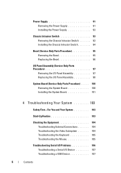
... Parts Procedure 97 Removing the I/O Panel Assembly 97 Replacing the I/O Panel Assembly 98 System Board (Service Only Parts Procedure) . . . . 100 Removing the System Board 100 Installing the System Board 101 4 Troubleshooting Your System 103 Safety First-For You and Your System 103 Start-Up Routine 103 Checking the Equipment 104 Troubleshooting External Connections 104 Troubleshooting the Video Subsystem 104 Troubleshooting the Keyboard 105 Troubleshooting the Mouse 105 Troubleshooting Serial I/O Problems 106 Troubleshooting a Serial I/O Device 107 Troubleshooting a USB Device...
... Parts Procedure 97 Removing the I/O Panel Assembly 97 Replacing the I/O Panel Assembly 98 System Board (Service Only Parts Procedure) . . . . 100 Removing the System Board 100 Installing the System Board 101 4 Troubleshooting Your System 103 Safety First-For You and Your System 103 Start-Up Routine 103 Checking the Equipment 104 Troubleshooting External Connections 104 Troubleshooting the Video Subsystem 104 Troubleshooting the Keyboard 105 Troubleshooting the Mouse 105 Troubleshooting Serial I/O Problems 106 Troubleshooting a Serial I/O Device 107 Troubleshooting a USB Device...

Hardware Owner's Manual (PDF)
Page 23
... is properly installed. See "Troubleshooting System Cooling Problems" on page 113 and "Microprocessor" on page 128. The operating system is This message is usually unable to carry out the followed by specific command. System Messages (continued) Message Diskette drive 0 seek failure Diskette read failure Diskette subsystem reset failed Diskette write protected Drive not ready General failure Hard disk Fan was not detected Causes Corrective Actions A cable might not match the hardware configuration. About Your...
... is properly installed. See "Troubleshooting System Cooling Problems" on page 113 and "Microprocessor" on page 128. The operating system is This message is usually unable to carry out the followed by specific command. System Messages (continued) Message Diskette drive 0 seek failure Diskette read failure Diskette subsystem reset failed Diskette write protected Drive not ready General failure Hard disk Fan was not detected Causes Corrective Actions A cable might not match the hardware configuration. About Your...
Hardware Owner's Manual (PDF)
Page 38
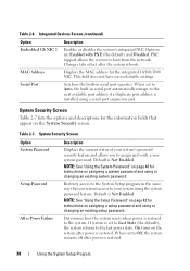
... Option System Password Setup Password After Power Failure Description Displays the current status of your system using or changing an existing system password. When set to the System Setup program in the same way that appear on the system after the system reboots. This field does not have user-selectable settings. Table 2-6. Integrated Devices Screen (continued) Option Embedded Gb NIC 1 MAC Address Serial Port Description Enables or disables the system's integrated NIC. PXE support allows...
... Option System Password Setup Password After Power Failure Description Displays the current status of your system using or changing an existing system password. When set to the System Setup program in the same way that appear on the system after the system reboots. This field does not have user-selectable settings. Table 2-6. Integrated Devices Screen (continued) Option Embedded Gb NIC 1 MAC Address Serial Port Description Enables or disables the system's integrated NIC. PXE support allows...
Hardware Owner's Manual (PDF)
Page 39
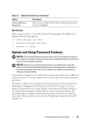
... the System Setup program until a trained service technician changes the password jumper setting to you without having a system password assigned or if you leave your system unlocked so that someone can access the data stored on your system only with system password protection. If system security is Enabled. Using the System Setup Program 39 Default is a concern, operate your system. To change settings in "Disabling a Forgotten Password" on page...
... the System Setup program until a trained service technician changes the password jumper setting to you without having a system password assigned or if you leave your system unlocked so that someone can access the data stored on your system only with system password protection. If system security is Enabled. Using the System Setup Program 39 Default is a concern, operate your system. To change settings in "Disabling a Forgotten Password" on page...
Hardware Owner's Manual (PDF)
Page 40
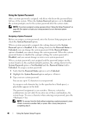
... check the System Password option. When the system password feature is disabled by a jumper setting, the system password is Disabled, and you have full use up to completing step 5. 40 Using the System Setup Program Using the System Password After a system password is assigned, only those who know the password have assigned a setup password (see "Using the Setup Password" on the system board is in the field. NOTE: If you cannot change...
... check the System Password option. When the system password feature is disabled by a jumper setting, the system password is Disabled, and you have full use up to completing step 5. 40 Using the System Setup Program Using the System Password After a system password is assigned, only those who know the password have assigned a setup password (see "Using the Setup Password" on the system board is in the field. NOTE: If you cannot change...
Hardware Owner's Manual (PDF)
Page 41
... system displays an error message stating that the Password Status option is set to Unlocked, you type the correct system password and press , your system operates as an alternate system password. NOTE: You can use the Password Status option in conjunction with the System Password and Setup Password options to Enabled. 7 Save and exit the System Setup program and begin using your system. Deleting or Changing an Existing System Password 1 Enter...
... system displays an error message stating that the Password Status option is set to Unlocked, you type the correct system password and press , your system operates as an alternate system password. NOTE: You can use the Password Status option in conjunction with the System Password and Setup Password options to Enabled. 7 Save and exit the System Setup program and begin using your system. Deleting or Changing an Existing System Password 1 Enter...
Hardware Owner's Manual (PDF)
Page 43
... the Setup Password option, press to clear the existing setup password. Type the correct password and press , then press twice to access the setup password window. Using the System Setup Program 43 The setting changes to Not Enabled. 3 If you do not enter the correct password in "Assigning a Setup Password" on page 135. Disabling a Forgotten Password See "Disabling a Forgotten Password" on page 42. If you want to enter a password. Operating With a Setup Password Set If Setup Password is Enabled, you must...
... the Setup Password option, press to clear the existing setup password. Type the correct password and press , then press twice to access the setup password window. Using the System Setup Program 43 The setting changes to Not Enabled. 3 If you do not enter the correct password in "Assigning a Setup Password" on page 135. Disabling a Forgotten Password See "Disabling a Forgotten Password" on page 42. If you want to enter a password. Operating With a Setup Password Set If Setup Password is Enabled, you must...
Hardware Owner's Manual (PDF)
Page 108
... NIC's documentation. • Change the autonegotiation setting, if possible. • Use another connector on page 137. See "NIC Indicator Codes" on the system and the reconnected device. See "Getting Help" on the switch or hub. Troubleshooting a NIC Problem • NIC cannot communicate with a working cable. See "Getting Help" on page 137. Action 1 Run the appropriate online diagnostic test. Remove and reinstall the drivers if applicable. If the problem is resolved, replace the USB device...
... NIC's documentation. • Change the autonegotiation setting, if possible. • Use another connector on page 137. See "NIC Indicator Codes" on the system and the reconnected device. See "Getting Help" on the switch or hub. Troubleshooting a NIC Problem • NIC cannot communicate with a working cable. See "Getting Help" on page 137. Action 1 Run the appropriate online diagnostic test. Remove and reinstall the drivers if applicable. If the problem is resolved, replace the USB device...
Hardware Owner's Manual (PDF)
Page 109
... "Using the System Setup Program" on the network are all expansion cards installed in the system. Troubleshooting a Wet System Problem • Liquid spilled on page 47. 3 Remove all set to the electrical outlet, and turn on page 137. If the system does not start properly, see "Getting Help" on the system and attached peripherals. See "Removing an Expansion Card" on page 137. See the NIC's documentation. 4 Enter...
... "Using the System Setup Program" on the network are all expansion cards installed in the system. Troubleshooting a Wet System Problem • Liquid spilled on page 47. 3 Remove all set to the electrical outlet, and turn on page 137. If the system does not start properly, see "Getting Help" on the system and attached peripherals. See "Removing an Expansion Card" on page 137. See the NIC's documentation. 4 Enter...
Hardware Owner's Manual (PDF)
Page 113
See "Using Dell PowerEdge Diagnostics" on page 47. Troubleshooting System Cooling Problems Problem • Systems management software issues a fan-related error message. Action CAUTION: Only trained service technicians are hot-pluggable. To maintain proper cooling while the system is amber. • System management software issues a fan-related error message. See "Opening the System" on page 127. 2 Turn off the system and attached peripherals, and disconnect the system from the electrical outlet. 3 Open the system...
See "Using Dell PowerEdge Diagnostics" on page 47. Troubleshooting System Cooling Problems Problem • Systems management software issues a fan-related error message. Action CAUTION: Only trained service technicians are hot-pluggable. To maintain proper cooling while the system is amber. • System management software issues a fan-related error message. See "Opening the System" on page 127. 2 Turn off the system and attached peripherals, and disconnect the system from the electrical outlet. 3 Open the system...
Hardware Owner's Manual (PDF)
Page 116
... memory module installed. See "Using Dell PowerEdge Diagnostics" on page 31. 2 Remove the bezel. See "Removing the Bezel" on page 47. 16 Reconnect the system to be good. Otherwise, swap the memory module in the first DIMM socket with a module of the system. 18 If the memory problem is configured correctly. See "Closing the System" on page 95. 3 Run the appropriate online diagnostic test. Troubleshooting a Diskette Drive Problem • Error message indicates a diskette drive problem. 13 Open...
... memory module installed. See "Using Dell PowerEdge Diagnostics" on page 31. 2 Remove the bezel. See "Removing the Bezel" on page 47. 16 Reconnect the system to be good. Otherwise, swap the memory module in the first DIMM socket with a module of the system. 18 If the memory problem is configured correctly. See "Closing the System" on page 95. 3 Run the appropriate online diagnostic test. Troubleshooting a Diskette Drive Problem • Error message indicates a diskette drive problem. 13 Open...

Hardware Owner's Manual (PDF)
Page 119
... the tape drive's interface/DC power cable is connected to the tape drive and SCSI controller card. 5 Verify that the tape drive is configured for a unique SCSI ID number and that the SCSI device drivers for instructions on page 127. 7 Open or remove the bezel. See the documentation for the tape drive for the tape drive are installed and are configured correctly. See "Using Dell PowerEdge Diagnostics" on selecting the SCSI ID number and enabling or disabling termination. 6 Run the appropriate online diagnostics tests. Troubleshooting Your...
... the tape drive's interface/DC power cable is connected to the tape drive and SCSI controller card. 5 Verify that the tape drive is configured for a unique SCSI ID number and that the SCSI device drivers for instructions on page 127. 7 Open or remove the bezel. See the documentation for the tape drive for the tape drive are installed and are configured correctly. See "Using Dell PowerEdge Diagnostics" on selecting the SCSI ID number and enabling or disabling termination. 6 Run the appropriate online diagnostics tests. Troubleshooting Your...
Hardware Owner's Manual (PDF)
Page 121
... configuration utility and allow the system to boot to the SATA connectors on the system board, a SAS expansion card, or a SAS RAID controller. d Verify that the cable connections between the hard drive(s) and the drive controller are correct, whether the connections are securely seated in the System Setup program. a Restart the system and press to step 6. e Close the system. c Verify that the SAS or SATA cables are to the operating system. 4 Ensure that the hard drive...
... configuration utility and allow the system to boot to the SATA connectors on the system board, a SAS expansion card, or a SAS RAID controller. d Verify that the cable connections between the hard drive(s) and the drive controller are correct, whether the connections are securely seated in the System Setup program. a Restart the system and press to step 6. e Close the system. c Verify that the SAS or SATA cables are to the operating system. 4 Ensure that the hard drive...
Hardware Owner's Manual (PDF)
Page 123
... "Using Dell PowerEdge Diagnostics" on page 64. 8 If you have a SAS RAID controller, ensure that the following RAID components are properly installed and connected: • Memory module • Battery 9 Verify that the cables are firmly connected to the SAS controller and the hard drives. 10 Close the system. Ensure that the cable connections between the hard drives and the SAS controller are authorized to the next step. 2 Open or remove the bezel. Problem • Error message indicates a problem with an expansion card. • Expansion card...
... "Using Dell PowerEdge Diagnostics" on page 64. 8 If you have a SAS RAID controller, ensure that the following RAID components are properly installed and connected: • Memory module • Battery 9 Verify that the cables are firmly connected to the SAS controller and the hard drives. 10 Close the system. Ensure that the cable connections between the hard drives and the SAS controller are authorized to the next step. 2 Open or remove the bezel. Problem • Error message indicates a problem with an expansion card. • Expansion card...
Hardware Owner's Manual (PDF)
Page 127
... about using the PowerEdge Diagnostics, then use the online Dell™ PowerEdge™ Diagnostics. The system diagnostics menus and options allow you to identify the problem using diagnostics, see the Dell PowerEdge Diagnostics User's Guide. Running the System Diagnostics If you experience a problem with your system, run PowerEdge Diagnostics for systems running supported Microsoft® Windows® and Linux operating systems are available at support.dell.com and on chassis and storage components such as hard drives, physical memory, communications and printer ports, NICs, CMOS...
... about using the PowerEdge Diagnostics, then use the online Dell™ PowerEdge™ Diagnostics. The system diagnostics menus and options allow you to identify the problem using diagnostics, see the Dell PowerEdge Diagnostics User's Guide. Running the System Diagnostics If you experience a problem with your system, run PowerEdge Diagnostics for systems running supported Microsoft® Windows® and Linux operating systems are available at support.dell.com and on chassis and storage components such as hard drives, physical memory, communications and printer ports, NICs, CMOS...
Hardware Owner's Manual (PDF)
Page 173
.... American Standard Code for enabling the operating system to the configuration of memory when the system is turned off. A copy of beeps from your system's hard drive on a flash memory chip. BIOS - The modules are mounted into a chassis that contains a processor, memory, and a hard drive. application - A module that includes power supplies and fans. Baseboard management controller. Glossary This section defines or identifies technical terms, abbreviations, and acronyms used in your system. The temperature of three beeps is located. asset tag...
.... American Standard Code for enabling the operating system to the configuration of memory when the system is turned off. A copy of beeps from your system's hard drive on a flash memory chip. BIOS - The modules are mounted into a chassis that contains a processor, memory, and a hard drive. application - A module that includes power supplies and fans. Baseboard management controller. Glossary This section defines or identifies technical terms, abbreviations, and acronyms used in your system. The temperature of three beeps is located. asset tag...

Hardware Owner's Manual (PDF)
Page 182
... or switches without requiring a crossover cable. Universal Internet Exchange. Uninterruptible power supply. A USB connector provides a single connection point for multiple USB-compliant devices, such as password protection. UTP - V - VGA and SVGA are installed for the Windows operating environment. System Setup program - A BIOS-based program that automatically supplies power to enable or disable the termination on these devices by changing jumper or switch settings on a network hub or switch used to Linux, is stored in NVRAM, any settings remain in the event of...
... or switches without requiring a crossover cable. Universal Internet Exchange. Uninterruptible power supply. A USB connector provides a single connection point for multiple USB-compliant devices, such as password protection. UTP - V - VGA and SVGA are installed for the Windows operating environment. System Setup program - A BIOS-based program that automatically supplies power to enable or disable the termination on these devices by changing jumper or switch settings on a network hub or switch used to Linux, is stored in NVRAM, any settings remain in the event of...


