

Getting Started Guide
Page 5
... the top cover is available on the system board. • Support for symmetric multiprocessing (SMP), which is opened. • An 800-W power supply. • Six system cooling fans. NOTE: DVD devices are data only. • An intrusion switch that supports multiprocessing. Getting Started ...With Your System 3 The upgrade kit from Dell. System Features The major hardware and software features of your system by installing a second processor, you must order the processor upgrade kits from...
... the top cover is available on the system board. • Support for symmetric multiprocessing (SMP), which is opened. • An 800-W power supply. • Six system cooling fans. NOTE: DVD devices are data only. • An intrusion switch that supports multiprocessing. Getting Started ...With Your System 3 The upgrade kit from Dell. System Features The major hardware and software features of your system by installing a second processor, you must order the processor upgrade kits from...
Getting Started Guide
Page 9
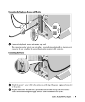
...With Your System 7 Connecting the Keyboard, Mouse, and Monitor Connect the keyboard, mouse, and monitor (optional). Plug the other end of the power supply and connect it to the cable clasp at the top of the cable into each connector. Be sure to plug into a grounded electrical ...outlet or a separate power source such as an uninterrupted power supply (UPS) or a power distribution unit (PDU). The connectors on the back of your system have icons indicating which cable to tighten the screws...
...With Your System 7 Connecting the Keyboard, Mouse, and Monitor Connect the keyboard, mouse, and monitor (optional). Plug the other end of the power supply and connect it to the cable clasp at the top of the cable into each connector. Be sure to plug into a grounded electrical ...outlet or a separate power source such as an uninterrupted power supply (UPS) or a power distribution unit (PDU). The connectors on the back of your system have icons indicating which cable to tighten the screws...
Getting Started Guide
Page 10
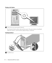
Turning on the System Turn on the system and the monitor. Installing the Bezel Install the bezel. 8 Getting Started With Your System Press the power button on the system and monitor (optional). Adjust the monitor's controls until the displayed image is satisfactory. The power indicators should light.
Turning on the System Turn on the system and the monitor. Installing the Bezel Install the bezel. 8 Getting Started With Your System Press the power button on the system and monitor (optional). Adjust the monitor's controls until the displayed image is satisfactory. The power indicators should light.
Getting Started Guide
Page 12
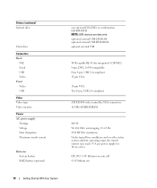
Drives (continued) Optical drive Flash drive Connectors Back NIC Serial USB Video Front Video USB Video Video type Video memory Power AC power supply Wattage Voltage Heat dissipation Maximum inrush current Batteries System battery RAID battery (optional) one optional CD, DVD, or combination CD-RW/DVD ...-63 Hz 2320 BTU/hr maximum Under typical line conditions and over the entire system ambient operating range, the inrush current may reach 55 A per power supply for integrated 1-GB NIC) 9-pin, DTE, 16550-compatible Four 4-pin, USB 2.0-compliant 15-pin VGA 15-pin VGA Two 4-pin, USB 2.0-compliant...
Drives (continued) Optical drive Flash drive Connectors Back NIC Serial USB Video Front Video USB Video Video type Video memory Power AC power supply Wattage Voltage Heat dissipation Maximum inrush current Batteries System battery RAID battery (optional) one optional CD, DVD, or combination CD-RW/DVD ...-63 Hz 2320 BTU/hr maximum Under typical line conditions and over the entire system ambient operating range, the inrush current may reach 55 A per power supply for integrated 1-GB NIC) 9-pin, DTE, 16550-compatible Four 4-pin, USB 2.0-compliant 15-pin VGA 15-pin VGA Two 4-pin, USB 2.0-compliant...
Hardware Owner's Manual (PDF)
Page 4
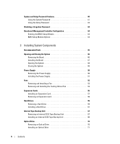
... and Closing the System 46 Removing the Bezel 46 Installing the Bezel 47 Opening the System 48 Closing the System 48 Power Supply 50 Removing the Power Supply 50 Installing the Power Supply 51 Fans 52 Removing and Installing a Fan 53 Removing and Installing the Cooling Shroud Fan 54 Expansion Cards 56 Installing...
... and Closing the System 46 Removing the Bezel 46 Installing the Bezel 47 Opening the System 48 Closing the System 48 Power Supply 50 Removing the Power Supply 50 Installing the Power Supply 51 Fans 52 Removing and Installing a Fan 53 Removing and Installing the Cooling Shroud Fan 54 Expansion Cards 56 Installing...
Hardware Owner's Manual (PDF)
Page 6
... a Serial I/O Device 105 Troubleshooting a USB Device 105 Troubleshooting a NIC 106 Troubleshooting a Wet System 106 Troubleshooting a Damaged System 107 Troubleshooting the System Battery 108 Troubleshooting the Power Supply 108 Troubleshooting System Cooling Problems 109 Troubleshooting a Fan 109 Troubleshooting System Memory 110 Troubleshooting a Diskette Drive 112 Troubleshooting an Optical Drive 113 Troubleshooting an...
... a Serial I/O Device 105 Troubleshooting a USB Device 105 Troubleshooting a NIC 106 Troubleshooting a Wet System 106 Troubleshooting a Damaged System 107 Troubleshooting the System Battery 108 Troubleshooting the Power Supply 108 Troubleshooting System Cooling Problems 109 Troubleshooting a Fan 109 Troubleshooting System Memory 110 Troubleshooting a Diskette Drive 112 Troubleshooting an Optical Drive 113 Troubleshooting an...

Hardware Owner's Manual (PDF)
Page 12
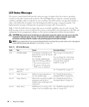
... pushed, the LCD panel on the front and the blue system status indicator on the back blink until one of whether the system has been powered on. 12 About Your System The LCD lights amber when the system needs attention, and the LCD panel displays an error code followed by the... operating system's documentation. The power button controls the DC power supply output to AC power and an error has been detected, the LCD lights amber regardless of the buttons is on the front and back panels...
... pushed, the LCD panel on the front and the blue system status indicator on the back blink until one of whether the system has been powered on. 12 About Your System The LCD lights amber when the system needs attention, and the LCD panel displays an error code followed by the... operating system's documentation. The power button controls the DC power supply output to AC power and an error has been detected, the LCD lights amber regardless of the buttons is on the front and back panels...
Hardware Owner's Manual (PDF)
Page 14
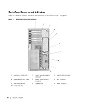
Figure 1-2. Back-Panel Features and Indicators 1 2 3 4 5 6 7 8 1 expansion-card slots (6) 4 system identification button 7 USB connectors (4) 10 serial connector 10 2 remote access connector (optional) 5 system status indicator connector 8 power supply 9 3 system status indicator 6 NIC connector 9 video connector 14 About Your System Back-Panel Features and Indicators Figure 1-2 shows the controls, indicators, and connectors located on the system's back panel.
Figure 1-2. Back-Panel Features and Indicators 1 2 3 4 5 6 7 8 1 expansion-card slots (6) 4 system identification button 7 USB connectors (4) 10 serial connector 10 2 remote access connector (optional) 5 system status indicator connector 8 power supply 9 3 system status indicator 6 NIC connector 9 video connector 14 About Your System Back-Panel Features and Indicators Figure 1-2 shows the controls, indicators, and connectors located on the system's back panel.
Hardware Owner's Manual (PDF)
Page 16
For information on page 108. 16 About Your System Setup program. Program" on page 33. • The power is out of messages with a lower priority. CMOS battery is missing, or the See "Troubleshooting the System voltage is off and active POST errors are... at least five seconds until an error code appears on page 109. NOTE: If your Product Information Guide for each message. Ambient system temperature is powered on page 131. Table 1-4. You can occur and the probable cause for complete information about safety precautions, working inside the system. See under the following...
For information on page 108. 16 About Your System Setup program. Program" on page 33. • The power is out of messages with a lower priority. CMOS battery is missing, or the See "Troubleshooting the System voltage is off and active POST errors are... at least five seconds until an error code appears on page 109. NOTE: If your Product Information Guide for each message. Ambient system temperature is powered on page 131. Table 1-4. You can occur and the probable cause for complete information about safety precautions, working inside the system. See under the following...
Hardware Owner's Manual (PDF)
Page 17
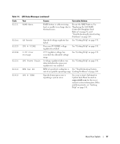
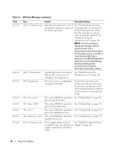
...Status Messages (continued) Code E1211 E12nn E1229 E122B E122C E1310 E1410 Text ROMB Batt XX PwrGd CPU # VCORE 0.9V Over Voltage CPU Power Fault RPM Fan ## CPU # IERR Causes Corrective Actions RAID battery is either missing, Reseat the RAID battery. Table 1-4. See bad,...issues. Processor # VCORE voltage regulator has failed. Controller Daughter Card Battery" on page 92, and "Troubleshooting System Cooling Problems" on support.dell.com for the most current system information. failed. See "Getting Help" on page 131. 0.9 V regulator voltage has exceeded the allowable ...
...Status Messages (continued) Code E1211 E12nn E1229 E122B E122C E1310 E1410 Text ROMB Batt XX PwrGd CPU # VCORE 0.9V Over Voltage CPU Power Fault RPM Fan ## CPU # IERR Causes Corrective Actions RAID battery is either missing, Reseat the RAID battery. Table 1-4. See bad,...issues. Processor # VCORE voltage regulator has failed. Controller Daughter Card Battery" on page 92, and "Troubleshooting System Cooling Problems" on support.dell.com for the most current system information. failed. See "Getting Help" on page 131. 0.9 V regulator voltage has exceeded the allowable ...
Hardware Owner's Manual (PDF)
Page 18
...LCD continues to display this message until the system's power cord is disconnected and reconnected to the type described in the Microprocessor Technical Specifications outlined in a configuration unsupported by Dell. specified power Supply" on page 131. The system BIOS has ...reported a See "Getting Help" on page 131. See the Dell OpenManage Baseboard Management Controller User's Guide for information about...
...LCD continues to display this message until the system's power cord is disconnected and reconnected to the type described in the Microprocessor Technical Specifications outlined in a configuration unsupported by Dell. specified power Supply" on page 131. The system BIOS has ...reported a See "Getting Help" on page 131. See the Dell OpenManage Baseboard Management Controller User's Guide for information about...
Hardware Owner's Manual (PDF)
Page 19
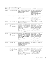
...expansion cards. LCD Status Messages (continued) Code E161C E1620 E1710 E1711 E1712 E1714 E171F Text Causes Corrective Actions PS # Input Lost Power source for specified power supply is unable to determine its origin. PCI PERR B## D## F## PCI PERR Slot # The system BIOS has reported a ... on page 131. If the problem persists, the The system BIOS has reported a system board is faulty. Check the AC power source for the specified power supply. If problem persists, see "Troubleshooting space at bus ##, device ##, function ##. Unknown Err The system BIOS has determined ...
...expansion cards. LCD Status Messages (continued) Code E161C E1620 E1710 E1711 E1712 E1714 E171F Text Causes Corrective Actions PS # Input Lost Power source for specified power supply is unable to determine its origin. PCI PERR B## D## F## PCI PERR Slot # The system BIOS has reported a ... on page 131. If the problem persists, the The system BIOS has reported a system board is faulty. Check the AC power source for the specified power supply. If problem persists, see "Troubleshooting space at bus ##, device ##, function ##. Unknown Err The system BIOS has determined ...
Hardware Owner's Manual (PDF)
Page 22
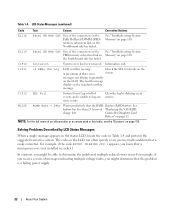
... Status Messages (continued) Code Text Causes Corrective Actions E2118 Fatal NB Mem CRC One of three error events. In contrast, you know that is a failing power supply. 22 About Your System The fourth message displays as the standard overflow message. The code on the LCD can display sequentially on page 110...
... Status Messages (continued) Code Text Causes Corrective Actions E2118 Fatal NB Mem CRC One of three error events. In contrast, you know that is a failing power supply. 22 About Your System The fourth message displays as the standard overflow message. The code on the LCD can display sequentially on page 110...
Hardware Owner's Manual (PDF)
Page 23
... explanation of the components inside the computer, and protecting against electrostatic discharge. wait approximately ten seconds, reconnect the power cable, and restart the system. See your Product Information Guide for the system. • Power cycle - been detected and is complete. when the temperature returns to the acceptable range, the message is running...
... explanation of the components inside the computer, and protecting against electrostatic discharge. wait approximately ten seconds, reconnect the power cable, and restart the system. See your Product Information Guide for the system. • Power cycle - been detected and is complete. when the temperature returns to the acceptable range, the message is running...
Hardware Owner's Manual (PDF)
Page 25
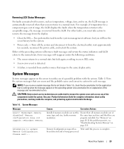
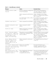
... "Troubleshooting a Diskette Drive" on page 80. Memory size reduced. Remote Access Controller initialization failure Ensure that only Dell-qualified memory is properly installed. Ensure that the Remote Access Controller is used. Faulty or improperly installed diskette Replace...failure Incorrect configuration settings in diskette drive. Loose diskette drive interface cable, or Reseat diskette drive interface cable, or loose power cable. Replace the diskette. correct the settings. Faulty or improperly seated memory See "Troubleshooting System Memory" module(s). See ...
... "Troubleshooting a Diskette Drive" on page 80. Memory size reduced. Remote Access Controller initialization failure Ensure that only Dell-qualified memory is properly installed. Ensure that the Remote Access Controller is used. Faulty or improperly installed diskette Replace...failure Incorrect configuration settings in diskette drive. Loose diskette drive interface cable, or Reseat diskette drive interface cable, or loose power cable. Replace the diskette. correct the settings. Faulty or improperly seated memory See "Troubleshooting System Memory" module(s). See ...

Hardware Owner's Manual (PDF)
Page 31
About Your System 31 For more information, see the systems management software documentation. Alert messages include information, status, warning, and failure messages for your system. Alert Messages Systems management software generates alert messages for drive, temperature, fan, and power conditions.
About Your System 31 For more information, see the systems management software documentation. Alert messages include information, status, warning, and failure messages for your system. Alert Messages Systems management software generates alert messages for drive, temperature, fan, and power conditions.
Hardware Owner's Manual (PDF)
Page 37
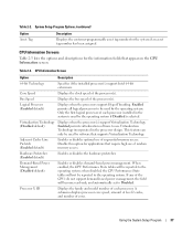
... software that appear on the CPU Information screen. Only the first logical processor of the CPUs do not support demand-based power management, the field will become read-only, and automatically set to be used by the operating system. Demand-Based... Power Management (Disabled default) Enables or disables demand-based power management. A submenu displays processor core speed, amount of level 2 cache, and number of the processor(s). System Setup Program Options (continued)...
... software that appear on the CPU Information screen. Only the first logical processor of the CPUs do not support demand-based power management, the field will become read-only, and automatically set to be used by the operating system. Demand-Based... Power Management (Disabled default) Enables or disables demand-based power management. A submenu displays processor core speed, amount of level 2 cache, and number of the processor(s). System Setup Program Options (continued)...
Hardware Owner's Manual (PDF)
Page 40
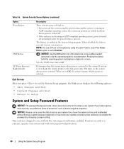
...or by changing a jumper setting. NOTICE: Use the NMI button only if directed to the system. NOTE: You can perform an orderly shutdown before power is turned off. • If the system is not running and unattended without the system password feature enabled. On turns on the system by ...using the power button and the system is running an ACPI-compliant operating system, the system can still turn on your data requires more security, use additional ...
...or by changing a jumper setting. NOTICE: Use the NMI button only if directed to the system. NOTE: You can perform an orderly shutdown before power is turned off. • If the system is not running and unattended without the system password feature enabled. On turns on the system by ...using the power button and the system is running an ACPI-compliant operating system, the system can still turn on your data requires more security, use additional ...
Hardware Owner's Manual (PDF)
Page 44
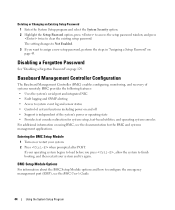
...; Fault logging and SNMP alerting • Access to system event log and sensor status • Control of system functions including power on and off • Support is independent of systems remotely. Entering the BMC Setup Module 1 Turn on page 43. Deleting...prompted after POST. Baseboard Management Controller Configuration The Baseboard Management Controller (BMC) enables configuring, monitoring, and recovery of the system's power or operating state • Provides text console redirection for the BMC and systems management applications. If your operating system begins to load...
...; Fault logging and SNMP alerting • Access to system event log and sensor status • Control of system functions including power on and off • Support is independent of systems remotely. Entering the BMC Setup Module 1 Turn on page 43. Deleting...prompted after POST. Baseboard Management Controller Configuration The Baseboard Management Controller (BMC) enables configuring, monitoring, and recovery of the system's power or operating state • Provides text console redirection for the BMC and systems management applications. If your operating system begins to load...
Hardware Owner's Manual (PDF)
Page 45
Installing System Components This section describes how to install the following system components: • Power supply • Cooling fans • Expansion cards • Hard drives • Tape, optical, and diskette drives • System battery • System memory • RAC card &#...
Installing System Components This section describes how to install the following system components: • Power supply • Cooling fans • Expansion cards • Hard drives • Tape, optical, and diskette drives • System battery • System memory • RAC card &#...


