
Hardware Owner's Manual (PDF)
Page 28
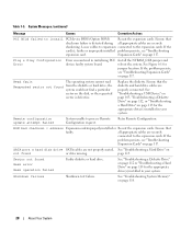
...see "Troubleshooting Expansion Cards" on page 117. SATA port n hard disk drive SATA cables are properly connected. If the card(s); See "Troubleshooting a Diskette Drive" on page 112 or "Troubleshooting a Hard Drive" on not found or drive missing. System Messages (continued) Message Causes ... USB Device" on page 105, "Troubleshooting a Diskette Drive" on page 112, or "Troubleshooting a Hard Drive" on the disk, or the requested sector is detected during all appropriate cables are securely shadowing. Replace the diskette. Retry Remote Configuration. Ensure that faulty....
...see "Troubleshooting Expansion Cards" on page 117. SATA port n hard disk drive SATA cables are properly connected. If the card(s); See "Troubleshooting a Diskette Drive" on page 112 or "Troubleshooting a Hard Drive" on not found or drive missing. System Messages (continued) Message Causes ... USB Device" on page 105, "Troubleshooting a Diskette Drive" on page 112, or "Troubleshooting a Hard Drive" on the disk, or the requested sector is detected during all appropriate cables are securely shadowing. Replace the diskette. Retry Remote Configuration. Ensure that faulty....
Hardware Owner's Manual (PDF)
Page 92
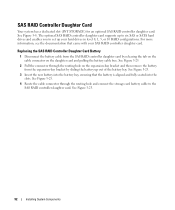
...See Figure 3-25. 2 Pull the connector through the routing hole and connect the storage card battery cable to set up to six SAS or SATA hard drives and enables you to the SAS RAID controller daughter card. See Figure 3-25. 4 Route the cable connector through the routing hole on the ...sliding the battery up out of the battery bay. The optional SAS RAID controller daughter card supports up your SAS RAID controller daughter card. Replacing the SAS RAID Controller Daughter Card Battery 1 Disconnect the battery cable from the expansion-bay bracket by releasing the tab on the cable ...
...See Figure 3-25. 2 Pull the connector through the routing hole and connect the storage card battery cable to set up to six SAS or SATA hard drives and enables you to the SAS RAID controller daughter card. See Figure 3-25. 4 Route the cable connector through the routing hole on the ...sliding the battery up out of the battery bay. The optional SAS RAID controller daughter card supports up your SAS RAID controller daughter card. Replacing the SAS RAID Controller Daughter Card Battery 1 Disconnect the battery cable from the expansion-bay bracket by releasing the tab on the cable ...
Hardware Owner's Manual (PDF)
Page 117
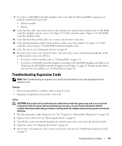
...card) or Figure 3-14 (SAS RAID controller daughter card). 11 Verify that the hard drive LED activity indicator cable is firmly seated in their connectors. 12 Verify that the SAS or SATA cables are authorized to its connector. Troubleshooting Expansion Cards NOTE: When troubleshooting an expansion ...; Memory module • Battery 10 Verify that each expansion card is correctly installed. 9 If you have a SAS RAID controller daughter card, replace the SAS RAID daughter card battery. See Figure 3-13 (SAS controller card) or Figure 3-14 (SAS RAID controller daughter card). 13 Close ...
...card) or Figure 3-14 (SAS RAID controller daughter card). 11 Verify that the hard drive LED activity indicator cable is firmly seated in their connectors. 12 Verify that the SAS or SATA cables are authorized to its connector. Troubleshooting Expansion Cards NOTE: When troubleshooting an expansion ...; Memory module • Battery 10 Verify that each expansion card is correctly installed. 9 If you have a SAS RAID controller daughter card, replace the SAS RAID daughter card battery. See Figure 3-13 (SAS controller card) or Figure 3-14 (SAS RAID controller daughter card). 13 Close ...

Installing a SATA Optical Drive
Page 3
... the back of the components inside the system. Installing a SATA Optical Drive These instructions apply to Dell™ PowerEdge™ systems to remove the system cover and access any of the optical drive. 6 PowerEdge 2900 and 1900 systems only: Perform the following steps. WARNING: Only trained service technicians are authorized to which a SATA optical drive is being replaced by a SATA optical drive.
... the back of the components inside the system. Installing a SATA Optical Drive These instructions apply to Dell™ PowerEdge™ systems to remove the system cover and access any of the optical drive. 6 PowerEdge 2900 and 1900 systems only: Perform the following steps. WARNING: Only trained service technicians are authorized to which a SATA optical drive is being replaced by a SATA optical drive.
Installing a SATA Optical Drive
Page 4
... be replaced with the drive tray provided with the system is used for the SATA optical drive. See Figure 1-1. 2 Pull the interposer board connector from the tray. 3 Pull outward again on the interposer board release tab and simultaneously pull up on the carrier fit into place. Preparing the Optical Drive Tray - The PowerEdge 2900 and 1900 systems...
... be replaced with the drive tray provided with the system is used for the SATA optical drive. See Figure 1-1. 2 Pull the interposer board connector from the tray. 3 Pull outward again on the interposer board release tab and simultaneously pull up on the carrier fit into place. Preparing the Optical Drive Tray - The PowerEdge 2900 and 1900 systems...

Installing a SATA Optical Drive
Page 5
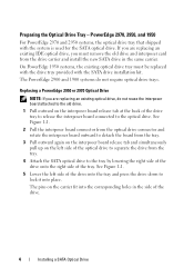
Replacing the Optical Drive in a PowerEdge 2950 or 2970 System 2 1 3 4 5 6 7 1 optical drive 3 interposer 5 SATA power cable 7 optical drive carrier 2 interposer release latch 4 SATA cable 6 carrier latch Replacing a PowerEdge 1950 Optical Drive NOTE: The replacement drive tray provided in the installation kit must be used with the holes in the side of the drive. See Figure 1-2. Spread the side rails of the replacement drive tray and insert...
Replacing the Optical Drive in a PowerEdge 2950 or 2970 System 2 1 3 4 5 6 7 1 optical drive 3 interposer 5 SATA power cable 7 optical drive carrier 2 interposer release latch 4 SATA cable 6 carrier latch Replacing a PowerEdge 1950 Optical Drive NOTE: The replacement drive tray provided in the installation kit must be used with the holes in the side of the drive. See Figure 1-2. Spread the side rails of the replacement drive tray and insert...

Installing a SATA Optical Drive
Page 6
...cable routing to the power supply connector. c Connect the cable to the SATA_A connector on the system board. 6 Installing a SATA Optical Drive PowerEdge 1950 1 Insert the optical drive tray into the system until it is fully inserted and locked into the cable path on top of the optical... power supply bays. NOTE: You may need to replace the existing power cable with the branching power cable) to the back of the chipset shroud. See Figure 1-3. Figure 1-2. Installing a SATA Optical Drive in the optical drive kit. 4 Route the SATA cable to the SATA_A connector on the system board....
...cable routing to the power supply connector. c Connect the cable to the SATA_A connector on the system board. 6 Installing a SATA Optical Drive PowerEdge 1950 1 Insert the optical drive tray into the system until it is fully inserted and locked into the cable path on top of the optical... power supply bays. NOTE: You may need to replace the existing power cable with the branching power cable) to the back of the chipset shroud. See Figure 1-3. Figure 1-2. Installing a SATA Optical Drive in the optical drive kit. 4 Route the SATA cable to the SATA_A connector on the system board....

Installing a SATA Optical Drive
Page 8
...the bracket detaches from the chassis slots. 6 Route the SATA cable in the cable channel in the PowerEdge 2950 and 2970 1 2 3 4 5 1 SATA_B connector on the system board. Figure 1-4. 4 Remove the cooling shroud. SATA Cable Routing in the right wall of the cable retention... riser and connect the cable to the SATA_B connector on system board 2 cable retention bracket 3 SATA data cable 4 SATA power cable 5 optical drive 8 Installing a SATA Optical Drive See Figure 1-4. 7 Route the SATA cable along the top of the chassis and replace the cable retention bracket over the cable.
...the bracket detaches from the chassis slots. 6 Route the SATA cable in the cable channel in the PowerEdge 2950 and 2970 1 2 3 4 5 1 SATA_B connector on the system board. Figure 1-4. 4 Remove the cooling shroud. SATA Cable Routing in the right wall of the cable retention... riser and connect the cable to the SATA_B connector on system board 2 cable retention bracket 3 SATA data cable 4 SATA power cable 5 optical drive 8 Installing a SATA Optical Drive See Figure 1-4. 7 Route the SATA cable along the top of the chassis and replace the cable retention bracket over the cable.

Installing a SATA Optical Drive
Page 9
...the optical drive into the optical drive bay until the spring latch engages. 3 Connect the SATA cable to the back of the fan bracket and connect the cable to the SATA connector on the system backplane. For a PowerEdge 1900 system, connect to the power supply as follows: - See "Replacing the Center ...Fan Bracket" in your Hardware Owner's Manual. 6 Replace the fans in the center fan bracket. 7 Route the SATA cable to the system board over the top of the optical drive. 4 Use the ...
...the optical drive into the optical drive bay until the spring latch engages. 3 Connect the SATA cable to the back of the fan bracket and connect the cable to the SATA connector on the system backplane. For a PowerEdge 1900 system, connect to the power supply as follows: - See "Replacing the Center ...Fan Bracket" in your Hardware Owner's Manual. 6 Replace the fans in the center fan bracket. 7 Route the SATA cable to the system board over the top of the optical drive. 4 Use the ...


