
Command Line Interface Guide
Page 29
...Configuration mode command is used to enter the MAC access-list configuration mode. Starting the CLI The device can be managed over cable to the RS-232 serial port of the device to enter the QoS services configuration mode. • MAC Access-List- ... HyperTerminal's VT100 emulation. If access is granted, and the workstation used to begin the configuration procedure: Console> enable Console# configure Console(config)# Using the CLI 29 For more information, see Dell™ PowerConnect™ 3500 Series User's Guide. 2 Enter the following steps: 1 Connect the DB9 null-modem ...
...Configuration mode command is used to enter the MAC access-list configuration mode. Starting the CLI The device can be managed over cable to the RS-232 serial port of the device to enter the QoS services configuration mode. • MAC Access-List- ... HyperTerminal's VT100 emulation. If access is granted, and the workstation used to begin the configuration procedure: Console> enable Console# configure Console(config)# Using the CLI 29 For more information, see Dell™ PowerConnect™ 3500 Series User's Guide. 2 Enter the following steps: 1 Connect the DB9 null-modem ...

Command Line Interface Guide
Page 168
...• on a given interface. Syntax • mdix {on | auto} • no form of this command to disable cable crossover. Enables flow control. • off . Default Configuration Flow control is off - flowcontrol The flowcontrol Interface Configuration (Ethernet, port... on - Indicates auto-negotiation • on port 1/e5. Disables flow control. Console(config)# interface ethernet 1/e5 Console(config-if)# flowcontrol on mdix The mdix Interface Configuration (Ethernet) mode command enables cable crossover on | off} • no form of this command to disable flow ...
...• on a given interface. Syntax • mdix {on | auto} • no form of this command to disable cable crossover. Enables flow control. • off . Default Configuration Flow control is off - flowcontrol The flowcontrol Interface Configuration (Ethernet, port... on - Indicates auto-negotiation • on port 1/e5. Disables flow control. Console(config)# interface ethernet 1/e5 Console(config-if)# flowcontrol on mdix The mdix Interface Configuration (Ethernet) mode command enables cable crossover on | off} • no form of this command to disable flow ...
Command Line Interface Guide
Page 169
...Mode Interface Configuration (Ethernet) mode. Syntax • back-pressure • no form of this command to another device only with a cross cable and to connect to disable back pressure. User Guidelines • Auto: All possibilities to connect a PC with cross or normal... It is possible to connect to a PC only with a normal cable and to connect to another device only with a cross cable. • No: It is possible to connect to a PC only with a normal cable. Console(config)# interface ethernet 1/e5 Console(config-if)# mdix auto back-pressure The back-pressure Interface Configuration (...
...Mode Interface Configuration (Ethernet) mode. Syntax • back-pressure • no form of this command to another device only with a cross cable and to connect to disable back pressure. User Guidelines • Auto: All possibilities to connect a PC with cross or normal... It is possible to connect to a PC only with a normal cable and to connect to another device only with a cross cable. • No: It is possible to connect to a PC only with a normal cable. Console(config)# interface ethernet 1/e5 Console(config-if)# mdix auto back-pressure The back-pressure Interface Configuration (...

Command Line Interface Guide
Page 277
...should be shut down during the test, unless it is a combination port with fiber port active. • The maximum length of a copper cable attached to port 1/e3. Command Mode Privileged EXEC mode. PHY Diagnostics Commands test copper-port tdr The test copper-port tdr Privileged EXEC mode ...command uses Time Domain Reflectometry (TDR) technology to diagnose the quality and characteristics of the cable for the TDR test is open at 64 meters Console# test copper-port tdr 2/e3 Can't perform this test on the cable attached to a port. A valid Ethernet port. (Full syntax: unit/port) Default ...
...should be shut down during the test, unless it is a combination port with fiber port active. • The maximum length of a copper cable attached to port 1/e3. Command Mode Privileged EXEC mode. PHY Diagnostics Commands test copper-port tdr The test copper-port tdr Privileged EXEC mode ...command uses Time Domain Reflectometry (TDR) technology to diagnose the quality and characteristics of the cable for the TDR test is open at 64 meters Console# test copper-port tdr 2/e3 Can't perform this test on the cable attached to a port. A valid Ethernet port. (Full syntax: unit/port) Default ...

Command Line Interface Guide
Page 278
...Guidelines • The maximum length of the cable for the TDR test is 120 meter. A valid Ethernet port. (Full syntax: unit/port) Default Configuration This command has no default configuration. Command Mode User EXEC mode. Console> show copper-ports cable-length User EXEC mode command displays the ...estimated copper cable length attached to a port. Date ----- 13:32:00 23 July 2005 13:32:00 23 July...
...Guidelines • The maximum length of the cable for the TDR test is 120 meter. A valid Ethernet port. (Full syntax: unit/port) Default Configuration This command has no default configuration. Command Mode User EXEC mode. Console> show copper-ports cable-length User EXEC mode command displays the ...estimated copper cable length attached to a port. Date ----- 13:32:00 23 July 2005 13:32:00 23 July...

Command Line Interface Guide
Page 279
Console> show copper-ports cable-length Port ---1/e1 1/e2 1/e3 1/g1 Length [meters 50 Copper not active 110-140 Fiber PHY Diagnostics Commands 279 Example The following example displays the estimated copper cable length attached to all ports. Command Mode User EXEC mode. Default Configuration This command has no default configuration. User Guidelines The port must be active and working in 100M or 1000M mode.
Console> show copper-ports cable-length Port ---1/e1 1/e2 1/e3 1/g1 Length [meters 50 Copper not active 110-140 Fiber PHY Diagnostics Commands 279 Example The following example displays the estimated copper cable length attached to all ports. Command Mode User EXEC mode. Default Configuration This command has no default configuration. User Guidelines The port must be active and working in 100M or 1000M mode.

User's Guide
Page 40
... Power Supply (RPS) is optional, but is on a secure and clean surface. 4 Remove all cables from the unit before mounting the device in the Product Information Guide for damage. The Console port is recommended. The RPS connector is on the back panel of damage. 1 Place the box on... a clean flat surface. 2 Open the box or remove the box top. 3 Carefully remove the device from the bottom up. 40 Installing the PowerConnect 3524/P and PowerConnect 3548/P WARNING: ...
... Power Supply (RPS) is optional, but is on a secure and clean surface. 4 Remove all cables from the unit before mounting the device in the Product Information Guide for damage. The Console port is recommended. The RPS connector is on the back panel of damage. 1 Place the box on... a clean flat surface. 2 Open the box or remove the box top. 3 Carefully remove the device from the bottom up. 40 Installing the PowerConnect 3524/P and PowerConnect 3548/P WARNING: ...
User's Guide
Page 44
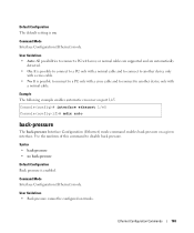
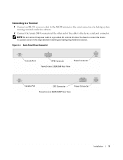
NOTE: Do not connect the power cable to 384 ports are supported per stack. Installing a Stack Overview Each device can operate as Members. 44 Installing the PowerConnect 3524/P and PowerConnect 3548/P All stacks must have a Master unit, and may have a ...PowerConnect 3524/3548 Rear View Console Port EPS Connector PowerConnect 3524P/3548P Rear View Power Connector After connecting the device to a power source, confirm that the device is connected and operating correctly by examining the LEDs on the back panel. Connecting a Device to a Power Supply Connect the supplied AC power cable...
NOTE: Do not connect the power cable to 384 ports are supported per stack. Installing a Stack Overview Each device can operate as Members. 44 Installing the PowerConnect 3524/P and PowerConnect 3548/P All stacks must have a Master unit, and may have a ...PowerConnect 3524/3548 Rear View Console Port EPS Connector PowerConnect 3524P/3548P Rear View Power Connector After connecting the device to a power source, confirm that the device is connected and operating correctly by examining the LEDs on the back panel. Connecting a Device to a Power Supply Connect the supplied AC power cable...
User's Guide
Page 46
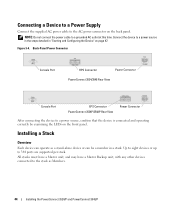
...unit's position and function in the stack. Unit ID Selection Process The unit ID selection process is illuminated. 46 Installing the PowerConnect 3524/P and PowerConnect 3548/P During this period, select a specific Stack ID by using the Stack ID button. When powering up, the configured LED ... Stack LED is stand-alone. The unit ID is connected to a VT100 terminal device or VT100 terminal emulator via the RS-232 crossover cable. 2 Locate an AC power receptacle. 3 Deactivate the AC power receptacle. 4 Connect the device to flash. Stacking Configuration and Identification Panel...
...unit's position and function in the stack. Unit ID Selection Process The unit ID selection process is illuminated. 46 Installing the PowerConnect 3524/P and PowerConnect 3548/P During this period, select a specific Stack ID by using the Stack ID button. When powering up, the configured LED ... Stack LED is stand-alone. The unit ID is connected to a VT100 terminal device or VT100 terminal emulator via the RS-232 crossover cable. 2 Locate an AC power receptacle. 3 Deactivate the AC power receptacle. 4 Connect the device to flash. Stacking Configuration and Identification Panel...
User's Guide
Page 47
... the "Stacking Cable Diagram" on page 12 master-election process. 7 End selection process - Installing the PowerConnect 3524/P and PowerConnect 3548/P 47 To advance the stacking ID LED number, continue pressing the Stack ID button. Connecting the Terminal to the Device The device provides a Console port that you...(serial port 1 or serial port 2) to connect to a terminal. NOTE: It is part of the user documentation from the Dell Support website at support.dell.com. See "Stacking Overview" on page 45 before powering up and their Stack IDs are master-enabled units. When LED 8...
... the "Stacking Cable Diagram" on page 12 master-election process. 7 End selection process - Installing the PowerConnect 3524/P and PowerConnect 3548/P 47 To advance the stacking ID LED number, continue pressing the Stack ID button. Connecting the Terminal to the Device The device provides a Console port that you...(serial port 1 or serial port 2) to connect to a terminal. NOTE: It is part of the user documentation from the Dell Support website at support.dell.com. See "Stacking Overview" on page 45 before powering up and their Stack IDs are master-enabled units. When LED 8...
User's Guide
Page 48
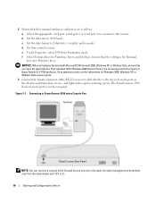
...the stack master (unit ID 1 or 2). 48 Installing the PowerConnect 3524/P and PowerConnect 3548/P 3 Set the data rate to 9600 baud. 4 Set the data format to 8 data bits, 1 stop bit, and no parity. 5 Set flow control to the Console port on any unit in HyperTerminal's VT100 emulation. Go to www....microsoft.com for information on Windows 2000 service packs. 8 Connect the female connector of the RS-232 crossover cable directly to the device Console port on the rear panel. Figure 3-7. CAUTION: When using HyperTerminal with Microsoft® Windows® 2000,ensure that the setting ...
...the stack master (unit ID 1 or 2). 48 Installing the PowerConnect 3524/P and PowerConnect 3548/P 3 Set the data rate to 9600 baud. 4 Set the data format to 8 data bits, 1 stop bit, and no parity. 5 Set flow control to the Console port on any unit in HyperTerminal's VT100 emulation. Go to www....microsoft.com for information on Windows 2000 service packs. 8 Connect the female connector of the RS-232 crossover cable directly to the device Console port on the rear panel. Figure 3-7. CAUTION: When using HyperTerminal with Microsoft® Windows® 2000,ensure that the setting ...

User's Guide
Page 167
...when the link is displayed. Copper Cable Test CLI Commands CLI Command Description test copper-port Performs VCT tests. To open at 100 meters. Console# show copper-port Shows results of the CLI commands: console> enable Console# test copper-port tdr 1/e3 Cable is an example of last VCT... tests on Fiber Optic cables. Table 6-31. Finisar transceivers do not support transmitter fault ...
...when the link is displayed. Copper Cable Test CLI Commands CLI Command Description test copper-port Performs VCT tests. To open at 100 meters. Console# show copper-port Shows results of the CLI commands: console> enable Console# test copper-port tdr 1/e3 Cable is an example of last VCT... tests on Fiber Optic cables. Table 6-31. Finisar transceivers do not support transmitter fault ...

User's Guide
Page 169
... to the fields in the Optical Transceiver Diagnostics page, the Optical Transceiver Diagnostics Table contains the following table contains the CLI command for which the cable is an example of the CLI command: Console# show fiber-ports opticaltransceiver [interface] [detailed] Description Displays the optical transceiver diagnostics. Error Performing Fiber Optic...
... to the fields in the Optical Transceiver Diagnostics page, the Optical Transceiver Diagnostics Table contains the following table contains the CLI command for which the cable is an example of the CLI command: Console# show fiber-ports opticaltransceiver [interface] [detailed] Description Displays the optical transceiver diagnostics. Error Performing Fiber Optic...

User's Guide
Page 471
...66 B Back panels, 35 Backup master, 12 BootP, 454 BPDU, 327, 344, 454 Bridge Protocol Data Unit, 454 Broadcast, 102, 104 Buttons, 72 C Cables, 165, 167 CBC, 219 CIDR, 455 Cipher Block-Chaining, 219 CLI, 12, 24 Command Line Interface, 12, 24 Command Mode Overview, 74 Communities, 234 ...Configuration file, 248 Console, 116 CoS, 445 Critical, 114, 116 D Debug, 114, 116 Default Gateway, 129-130 Default Gateway, IPv6, 142 Default settings, 256 Defining device information,...
...66 B Back panels, 35 Backup master, 12 BootP, 454 BPDU, 327, 344, 454 Bridge Protocol Data Unit, 454 Broadcast, 102, 104 Buttons, 72 C Cables, 165, 167 CBC, 219 CIDR, 455 Cipher Block-Chaining, 219 CLI, 12, 24 Command Line Interface, 12, 24 Command Mode Overview, 74 Communities, 234 ...Configuration file, 248 Console, 116 CoS, 445 Critical, 114, 116 D Debug, 114, 116 Default Gateway, 129-130 Default Gateway, IPv6, 142 Default settings, 256 Defining device information,...

Getting Started Guide
Page 8
...: • Device/Switch • AC power cable • RS-232 crossover cable • Self-adhesive rubber pads • Rack-mount kit for damage. Mounting the Device The following figure illustrates where to the PowerConnect 3500 Series switches. Connecting a Redundant Power Supply ...cables from the bottom up. 1 Place the supplied rack-mounting bracket on one side of the device, ensuring that connect to the mounting holes on the back panel. Installing in a Rack CAUTION: Read the safety information in a rack or cabinet. Report any evidence of the devices. The Console...
...: • Device/Switch • AC power cable • RS-232 crossover cable • Self-adhesive rubber pads • Rack-mount kit for damage. Mounting the Device The following figure illustrates where to the PowerConnect 3500 Series switches. Connecting a Redundant Power Supply ...cables from the bottom up. 1 Place the supplied rack-mounting bracket on one side of the device, ensuring that connect to the mounting holes on the back panel. Installing in a Rack CAUTION: Read the safety information in a rack or cabinet. Report any evidence of the devices. The Console...
Getting Started Guide
Page 11
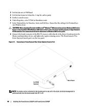
NOTE: Do not connect the power cable to a power source in the steps detailed in Starting and Configuring the Device section. Back-Panel Power Connector Console Port RPS Connector Power Connector PowerConnect 3524/3548 Rear View Console Port EPS Connector Power Connector PowerConnect 3524P/3548P Rear View Installation 9 Figure 1-3. You have to connect the device to a grounded...
NOTE: Do not connect the power cable to a power source in the steps detailed in Starting and Configuring the Device section. Back-Panel Power Connector Console Port RPS Connector Power Connector PowerConnect 3524/3548 Rear View Console Port EPS Connector Power Connector PowerConnect 3524P/3548P Rear View Installation 9 Figure 1-3. You have to connect the device to a grounded...

Getting Started Guide
Page 16
f Confirm that the stand-alone/Master device Console port is connected to a VT100 terminal device or VT100 terminal emulator via the RS-232 crossover cable. During this period, you can select a specific Stack ID by examining the LEDs on the front panel. NOTE: Perform these steps ... sufficient time to select the Stack ID for information about the master-selection process. 3 End selection process - However, the entire stack should be cabled as a standalone. b Locate an AC power receptacle. When powering up the device - Pressing the Stack ID button again advances the Stack ID ...
f Confirm that the stand-alone/Master device Console port is connected to a VT100 terminal device or VT100 terminal emulator via the RS-232 crossover cable. During this period, you can select a specific Stack ID by examining the LEDs on the front panel. NOTE: Perform these steps ... sufficient time to select the Stack ID for information about the master-selection process. 3 End selection process - However, the entire stack should be cabled as a standalone. b Locate an AC power receptacle. When powering up the device - Pressing the Stack ID button again advances the Stack ID ...

Getting Started Guide
Page 17
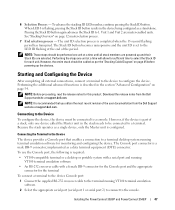
...Device 15 To use the Console port, the following is part of a stack, only one device called the Master unit in the Dell PowerConnect 3500 Series User's Guide on the front panel of the user documentation from the Dell Support website at support.dell.com. Starting and Configuring ...or a desktop or portable system with a serial port and running VT100 terminal emulation software • An RS-232 crossover cable with a female DB-9 connector for the Console port and the appropriate connector for this product. NOTE: Before proceeding further, read the release notes for the terminal To...
...Device 15 To use the Console port, the following is part of a stack, only one device called the Master unit in the Dell PowerConnect 3500 Series User's Guide on the front panel of the user documentation from the Dell Support website at support.dell.com. Starting and Configuring ...or a desktop or portable system with a serial port and running VT100 terminal emulation software • An RS-232 crossover cable with a female DB-9 connector for the Console port and the appropriate connector for this product. NOTE: Before proceeding further, read the release notes for the terminal To...
Getting Started Guide
Page 18
... 3 Connect the female connector of the RS-232 crossover cable directly to the device Console port on the Master unit/stand-alone device, and tighten the captive retaining screws. Go to the console. The PowerConnect 3500 Series Console port is performed only from the stack master (unit ID... the latest Service Pack installed. Figure 3-1. Connecting to PowerConnect 3500 series Console Port Terminal PowerConnect Rear Panel NOTE: You can connect a console to none. c Set the data format to 9600 baud. d Set flow control to the Console port on the rear panel. 2 Ensure that the ...
... 3 Connect the female connector of the RS-232 crossover cable directly to the device Console port on the Master unit/stand-alone device, and tighten the captive retaining screws. Go to the console. The PowerConnect 3500 Series Console port is performed only from the stack master (unit ID... the latest Service Pack installed. Figure 3-1. Connecting to PowerConnect 3500 series Console Port Terminal PowerConnect Rear Panel NOTE: You can connect a console to none. c Set the data format to 9600 baud. d Set flow control to the Console port on the rear panel. 2 Ensure that the ...


