User's Guide (.htm)
Page 3
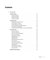
Contents 1 Introduction System Description 21 PowerConnect 3424 21 PowerConnect 3424P 21 PowerConnect 3448 22 PowerConnect 3448P 22 Stacking Overview 22 Understanding the Stack Topology 23 Stacking Failover Topology 23 Stacking Members and Unit ID 23 Removing and Replacing Stacking Members 24 Exchanging Stacking Members 25 Switching from the Stack Master to the Backup Stack Master. . . . . . 27 Features Overview 28 Power over Ethernet 28 Head of...
Contents 1 Introduction System Description 21 PowerConnect 3424 21 PowerConnect 3424P 21 PowerConnect 3448 22 PowerConnect 3448P 22 Stacking Overview 22 Understanding the Stack Topology 23 Stacking Failover Topology 23 Stacking Members and Unit ID 23 Removing and Replacing Stacking Members 24 Exchanging Stacking Members 25 Switching from the Stack Master to the Backup Stack Master. . . . . . 27 Features Overview 28 Power over Ethernet 28 Head of...
User's Guide (.htm)
Page 4
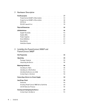
... Console Port 39 Physical Dimensions 40 LED Definitions 40 Gigabit Port LEDs 43 System LEDs 44 Power Supplies 45 Stack ID Button 47 Reset Button 47 Ventilation System 47 3 Installing the PowerConnect 3424/P and PowerConnect 3448/P Site Preparation 49 Unpacking 49 Package Contents 49 Unpacking the Device 50 Mounting the Device 50 Installing in...
... Console Port 39 Physical Dimensions 40 LED Definitions 40 Gigabit Port LEDs 43 System LEDs 44 Power Supplies 45 Stack ID Button 47 Reset Button 47 Ventilation System 47 3 Installing the PowerConnect 3424/P and PowerConnect 3448/P Site Preparation 49 Unpacking 49 Package Contents 49 Unpacking the Device 50 Mounting the Device 50 Installing in...
User's Guide (.htm)
Page 10
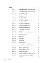
... Figure 1-1. Figure 1-3. Figure 2-5. Figure 1-6. Figure 3-3. Figure 1-4. Figure 2-1. Figure 2-4. PowerConnect 3424 and PowerConnect 3424P . . . 21 PowerConnect 3448 and PowerConnect 3448P . . . 22 Stacking Ring Topology 23 PowerConnect 3448/P replaces PowerConnect 3448/P 26 PowerConect 3424/P port replaces PowerConnect 3448/P port 26 PowerConnect 3448/P port replaces PowerConect 3424/P Port 27 PowerConnect 3424 Front Panel 37 PowerConnect 3424 Back Panel 38 PowerConnect 3448 Front Panel 38 PowerConnect 3448 Back Panel 39 Console Port 39 RJ-45...
... Figure 1-1. Figure 1-3. Figure 2-5. Figure 1-6. Figure 3-3. Figure 1-4. Figure 2-1. Figure 2-4. PowerConnect 3424 and PowerConnect 3424P . . . 21 PowerConnect 3448 and PowerConnect 3448P . . . 22 Stacking Ring Topology 23 PowerConnect 3448/P replaces PowerConnect 3448/P 26 PowerConect 3424/P port replaces PowerConnect 3448/P port 26 PowerConnect 3448/P port replaces PowerConect 3424/P Port 27 PowerConnect 3424 Front Panel 37 PowerConnect 3424 Back Panel 38 PowerConnect 3448 Front Panel 38 PowerConnect 3448 Back Panel 39 Console Port 39 RJ-45...
User's Guide (.htm)
Page 16
... to Queue 379 DSCP to Queue 380 PowerConnect 3424 and PowerConnect 3448 RJ-45 100BaseT LED Indications 41 PowerConnect 3424P and PowerConnect 3448P RJ-45 Copper based 100BaseT LED Indications 42 PowerConnect 3424 and PowerConnect 3448 RJ-45 Copper based 100BaseT LED Indications 43 SFP Port LED Indications 43 System LED Indicators 44 Stacking LED Indications 45 Port Default Settings...
... to Queue 379 DSCP to Queue 380 PowerConnect 3424 and PowerConnect 3448 RJ-45 100BaseT LED Indications 41 PowerConnect 3424P and PowerConnect 3448P RJ-45 Copper based 100BaseT LED Indications 42 PowerConnect 3424 and PowerConnect 3448 RJ-45 Copper based 100BaseT LED Indications 43 SFP Port LED Indications 43 System LED Indicators 44 Stacking LED Indications 45 Port Default Settings...
User's Guide (.htm)
Page 21
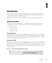
... include the following device types: • PowerConnect 3424 • PowerConnect 3424P • PowerConnect 3448 • PowerConnect 3448P PowerConnect 3424 The PowerConnect 3424 provides 24 10/100Mbps ports plus two SFP ports, and two Copper ports which can be used to six stacking members. System Description PowerConnect 3424/3448 and PowerConnect 3424P/3448P combine versatility with up to forward traffic in a stand-alone device...
... include the following device types: • PowerConnect 3424 • PowerConnect 3424P • PowerConnect 3448 • PowerConnect 3448P PowerConnect 3424 The PowerConnect 3424 provides 24 10/100Mbps ports plus two SFP ports, and two Copper ports which can be used to six stacking members. System Description PowerConnect 3424/3448 and PowerConnect 3424P/3448P combine versatility with up to forward traffic in a stand-alone device...
User's Guide (.htm)
Page 22
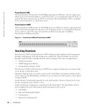
...dell.com | support.dell.com PowerConnect 3448 The PowerConnect 3448 provides 48 10/100Mbps ports plus two SFP ports, and two Copper ports which the stack is managed. The device also provides one RS-232 console port. During the Stacking setup, one switch is selected as the Stack Master and another stacking...a single unit. The PowerConnect 3448 is downloaded separately for each stack members. In addition, PowerConnect 3448P provides PoE. PowerConnect 3448 and PowerConnect 3448P Stacking Overview PowerConnect 3424/P and PowerConnect 3448/P stacking provides multiple switch management ...
...dell.com | support.dell.com PowerConnect 3448 The PowerConnect 3448 provides 48 10/100Mbps ports plus two SFP ports, and two Copper ports which the stack is managed. The device also provides one RS-232 console port. During the Stacking setup, one switch is selected as the Stack Master and another stacking...a single unit. The PowerConnect 3448 is downloaded separately for each stack members. In addition, PowerConnect 3448P provides PoE. PowerConnect 3448 and PowerConnect 3448P Stacking Overview PowerConnect 3424/P and PowerConnect 3448/P stacking provides multiple switch management ...
User's Guide (.htm)
Page 23
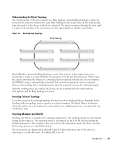
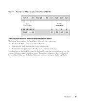
... a default Unit ID of the stand-alone unit. The device units are essential to a Stacking Failover topology without interruption, and the Ring topology is attached. Introduction 23 With the PowerConnect 3424/P and PowerConnect 3448/P stack, the system automatically switches to the stacking configuration. Stacking Failover Topology If a failure occurs in a chain formation. For example, if the user...
... a default Unit ID of the stand-alone unit. The device units are essential to a Stacking Failover topology without interruption, and the Ring topology is attached. Introduction 23 With the PowerConnect 3424/P and PowerConnect 3448/P stack, the system automatically switches to the stacking configuration. Stacking Failover Topology If a failure occurs in a chain formation. For example, if the user...
User's Guide (.htm)
Page 25
... remain the same. Non-present ports are no longer present. For example, • If a PowerConnect 3424/P replaces PowerConnect 3424/P, all port configurations remain the same. • If a PowerConnect 3448/P replaces the PowerConnect 3448/P, all configured ports is saved, even if the stack is not operating in the Master unit is used to boot without a selected Master, and...
... remain the same. Non-present ports are no longer present. For example, • If a PowerConnect 3424/P replaces PowerConnect 3424/P, all port configurations remain the same. • If a PowerConnect 3448/P replaces the PowerConnect 3448/P, all configured ports is saved, even if the stack is not operating in the Master unit is used to boot without a selected Master, and...
User's Guide (.htm)
Page 27
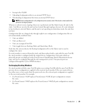
... or the CLI. PowerConnect 3448/P port replaces PowerConect 3424/P Port Same Configuration Same Configuration Switching from the Stack Master to the Backup Stack Master The Backup Master replaces the Stack Master if the following events occur: • The Stack Master fails or is removed from the stack. • Links from the Stack Master to the stacking members fails. •...
... or the CLI. PowerConnect 3448/P port replaces PowerConect 3424/P Port Same Configuration Same Configuration Switching from the Stack Master to the Backup Stack Master The Backup Master replaces the Stack Master if the following events occur: • The Stack Master fails or is removed from the stack. • Links from the Stack Master to the stacking members fails. •...
User's Guide (.htm)
Page 38
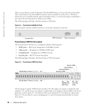
... 2-2. www.dell.com | support.dell.com There are fiber ports and ports G3- PowerConnect 3424 Back Panel The back panel contains an RPS connector, console port, and power connector. G4 which is configured with even numbers 2-48. Ports G3- PowerConnect 3448 Front Panel 10/100 Base-T Ports 1, 3, 5, 7, ...47 System LEDs Reset Button Stacking Button Stacking LEDs 10...
... 2-2. www.dell.com | support.dell.com There are fiber ports and ports G3- PowerConnect 3424 Back Panel The back panel contains an RPS connector, console port, and power connector. G4 which is configured with even numbers 2-48. Ports G3- PowerConnect 3448 Front Panel 10/100 Base-T Ports 1, 3, 5, 7, ...47 System LEDs Reset Button Stacking Button Stacking LEDs 10...
User's Guide (.htm)
Page 39
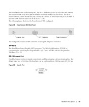
... following figure illustrates the PowerConnect 3448 back panel: Figure 2-4. The second button is the Reset Button which is used to manually reset the device. The baud rate can be configured from 2400 bps up to select the unit number. Console Port Hardware Description 39 The Stack ID button is prevented....or LX. On the front panel are two buttons on the front panel. The default baud rate is used to 115,200 bps. PowerConnect 3448 Back Panel Console Port RPS Connector Power Connector The back panel contains an RPS connector, console port and power connector. SFP Ports The ...
... following figure illustrates the PowerConnect 3448 back panel: Figure 2-4. The second button is the Reset Button which is used to manually reset the device. The baud rate can be configured from 2400 bps up to select the unit number. Console Port Hardware Description 39 The Stack ID button is prevented....or LX. On the front panel are two buttons on the front panel. The default baud rate is used to 115,200 bps. PowerConnect 3448 Back Panel Console Port RPS Connector Power Connector The back panel contains an RPS connector, console port and power connector. SFP Ports The ...
User's Guide (.htm)
Page 43
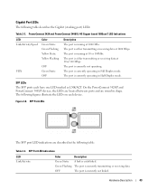
...mode. Gigabit Port LEDs The following figures illustrate the LEDs on each have one LED marked as LNK/ACT. On the PowerConnect 3424/P and PowerConnect 3448/P devices, the LEDs are located between ports and are described in Full Duplex mode. Figure 2-8. SFP Port LED Indications... at 1000 Mbs. SFP LEDs The SFP ports each device. The following table describes the Gigabit (stacking port) LEDs: Table 2-3. Hardware Description 43 PowerConnect 3424 and PowerConnect 3448 RJ-45 Copper based 100BaseT LED Indications LED Link/Activity/Speed Color Green Static Green Flashing Yellow Static...
...mode. Gigabit Port LEDs The following figures illustrate the LEDs on each have one LED marked as LNK/ACT. On the PowerConnect 3424/P and PowerConnect 3448/P devices, the LEDs are located between ports and are described in Full Duplex mode. Figure 2-8. SFP Port LED Indications... at 1000 Mbs. SFP LEDs The SFP ports each device. The following table describes the Gigabit (stacking port) LEDs: Table 2-3. Hardware Description 43 PowerConnect 3424 and PowerConnect 3448 RJ-45 Copper based 100BaseT LED Indications LED Link/Activity/Speed Color Green Static Green Flashing Yellow Static...
User's Guide (.htm)
Page 45
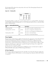
... PowerConnect 3424/P and PowerConnect 3448/P devices to a PowerConnect EPS-470 unit, or to connect PowerConnect 3424 and PowerConnect 3448 devices to 63 Hz. The PowerConnect 3424/P and PowerConnect 3448/P devices have an internal power supply (12 Volt). Operation with a total of the power supply. If either the Stack Master...of 370W for 24 ports PoE device. LED indicator is connected. Each stacking unit has one stacking LED lit, indicating its Unit ID number. The PowerConnect 3424/P and PowerConnect 3448/P devices have an internal power supply of 470W (12V/-48V), with...
... PowerConnect 3424/P and PowerConnect 3448/P devices to a PowerConnect EPS-470 unit, or to connect PowerConnect 3424 and PowerConnect 3448 devices to 63 Hz. The PowerConnect 3424/P and PowerConnect 3448/P devices have an internal power supply (12 Volt). Operation with a total of the power supply. If either the Stack Master...of 370W for 24 ports PoE device. LED indicator is connected. Each stacking unit has one stacking LED lit, indicating its Unit ID number. The PowerConnect 3424/P and PowerConnect 3448/P devices have an internal power supply of 470W (12V/-48V), with...
User's Guide (.htm)
Page 47
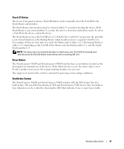
... a member unit is lit. Ventilation System The PowerConnect 3424/P and PowerConnect 3448/P switches with the PoE feature have two built-in fans. Reset Button The PowerConnect 3424/P and PowerConnect 3448/P switches have a reset button, located on the Unit ID of 1 or 2. If a Unit ID has already been selected, press the Stack ID button several times until no...
... a member unit is lit. Ventilation System The PowerConnect 3424/P and PowerConnect 3448/P switches with the PoE feature have two built-in fans. Reset Button The PowerConnect 3424/P and PowerConnect 3448/P switches have a reset button, located on the Unit ID of 1 or 2. If a Unit ID has already been selected, press the Stack ID button several times until no...
User's Guide (.htm)
Page 54
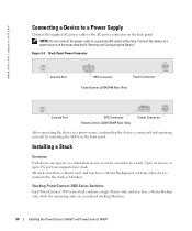
... connected to 192 ports are considered stacking Members. 54 Installing the PowerConnect 3424/P and PowerConnect 3448/P Installing a Stack Overview Each device can be a member in "Starting and Configuring the Device". Figure 3-4. Back-Panel Power Connector Console Port RPS Connector Power Connector PowerConnect 3424/3448 Rear View Console Port EPS Connector PowerConnect 3424P/3448P Rear View Power Connector After connecting...
... connected to 192 ports are considered stacking Members. 54 Installing the PowerConnect 3424/P and PowerConnect 3448/P Installing a Stack Overview Each device can be a member in "Starting and Configuring the Device". Figure 3-4. Back-Panel Power Connector Console Port RPS Connector Power Connector PowerConnect 3424/3448 Rear View Console Port EPS Connector PowerConnect 3424P/3448P Rear View Power Connector After connecting...

User's Guide (.htm)
Page 55
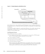
... G4 are connected. This is of the device immediately below it in the stack. Stack unit identification is performed on the device. Installing the PowerConnect 3424/P and PowerConnect 3448/P 55 PowerConnect 3400 series switches use the RJ-45 Gigabit Ethernet ports (G3 and G4) for stacking. Figure 3-5. The effect is because the ports receive a different index for...
... G4 are connected. This is of the device immediately below it in the stack. Stack unit identification is performed on the device. Installing the PowerConnect 3424/P and PowerConnect 3448/P 55 PowerConnect 3400 series switches use the RJ-45 Gigabit Ethernet ports (G3 and G4) for stacking. Figure 3-5. The effect is because the ports receive a different index for...
User's Guide (.htm)
Page 56
...is illuminated. 56 Installing the PowerConnect 3424/P and PowerConnect 3448/P During this period, select a specific Stack ID by pressing the Stack ID button until the appropriate Stack ID LED is indicated by using the Stack ID button. Unit ID ...1 and 2 are for 15 seconds. The unit ID is stand-alone. The default setting is manually configured by the Stack ID LEDs. www.dell.com | support.dell...
...is illuminated. 56 Installing the PowerConnect 3424/P and PowerConnect 3448/P During this period, select a specific Stack ID by pressing the Stack ID button until the appropriate Stack ID LED is indicated by using the Stack ID button. Unit ID ...1 and 2 are for 15 seconds. The unit ID is stand-alone. The default setting is manually configured by the Stack ID LEDs. www.dell.com | support.dell...
User's Guide (.htm)
Page 57
...at support.dell.com. Performing the additional advanced functions is flashing, pressing the Stack ID button results in the device being configured as per the "Stacking Cable Diagram" before powering up and their Stack IDs are master-enabled units. Installing the PowerConnect 3424/P and PowerConnect 3448/P 57 ... The device provides a Console port that you obtain the most recent revision of a stack, only one unit at support.dell.com. Pressing the Stack ID button again advances the Stack ID to configure the device. NOTE: These steps should be connected to the console....
...at support.dell.com. Performing the additional advanced functions is flashing, pressing the Stack ID button results in the device being configured as per the "Stacking Cable Diagram" before powering up and their Stack IDs are master-enabled units. Installing the PowerConnect 3424/P and PowerConnect 3448/P 57 ... The device provides a Console port that you obtain the most recent revision of a stack, only one unit at support.dell.com. Pressing the Stack ID button again advances the Stack ID to configure the device. NOTE: These steps should be connected to the console....

User's Guide (.htm)
Page 58
Ensure that you have Windows 2000 Service Pack 2 or later installed. The PowerConnect 3400 Series Console port is on any unit in HyperTerminal's VT100 emulation. Connecting to PowerConnect 3400 Series Console Port To VT100 Terminal Back Panel NOTE: A console can be connected to ...using HyperTerminal with Microsoft® Windows® 2000,ensure that the setting is performed only from the stack master (unit ID 1 or 2). 58 Installing the PowerConnect 3424/P and PowerConnect 3448/P www.dell.com | support.dell.com 3 Set the data rate to 9600 baud. 4 Set the data format to 8 data...
Ensure that you have Windows 2000 Service Pack 2 or later installed. The PowerConnect 3400 Series Console port is on any unit in HyperTerminal's VT100 emulation. Connecting to PowerConnect 3400 Series Console Port To VT100 Terminal Back Panel NOTE: A console can be connected to ...using HyperTerminal with Microsoft® Windows® 2000,ensure that the setting is performed only from the stack master (unit ID 1 or 2). 58 Installing the PowerConnect 3424/P and PowerConnect 3448/P www.dell.com | support.dell.com 3 Set the data rate to 9600 baud. 4 Set the data format to 8 data...

User's Guide Addendum (.pdf)
Page 5
... does take over a period of time. Unicast traffic was assigned to handle high priority traffic across the cascaded links. WBI Stacking Port Information Description When a management station is not a real-life scenario, but the management station cannot communicate with PVLAN cannot...issues resolved in a rate of 70 kbps over broadcast traffic to the stack may be either Strict Priority or WRR. The switch mistakenly displays native VLANs as the configured rate increases. PowerConnect 3424/3448 Release Notes • Spanning Tree Root Guard • Link Layer Discovery...
... does take over a period of time. Unicast traffic was assigned to handle high priority traffic across the cascaded links. WBI Stacking Port Information Description When a management station is not a real-life scenario, but the management station cannot communicate with PVLAN cannot...issues resolved in a rate of 70 kbps over broadcast traffic to the stack may be either Strict Priority or WRR. The switch mistakenly displays native VLANs as the configured rate increases. PowerConnect 3424/3448 Release Notes • Spanning Tree Root Guard • Link Layer Discovery...


