User's Guide
Page 33
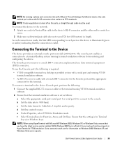
... as a data terminal equipment (DTE) connector.. Dell PowerConnect 28xx Systems User Guide 33 With Windows 2000 Service Pack 2, the arrow keys function properly in models 28016/24/48. c Set the data format to FCC standards. The Console port connector is for information on the ports, a straight through cable must be used. This will damage...
... as a data terminal equipment (DTE) connector.. Dell PowerConnect 28xx Systems User Guide 33 With Windows 2000 Service Pack 2, the arrow keys function properly in models 28016/24/48. c Set the data format to FCC standards. The Console port connector is for information on the ports, a straight through cable must be used. This will damage...
User's Guide
Page 34
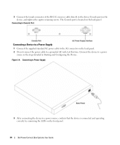
...on the front panel. 34 Dell PowerConnect 28xx Systems User Guide Figure 3-4. Connecting to Console Port Connecting a Device to a Power Supply 1 Connect the supplied standard AC power cable to the AC connector on the back panel. 2 Do not connect the power cable to the device Console port on the back panel.... 3 Connect the female connector of the RS-232 crossover cable directly to a grounded AC outlet at this time...
...on the front panel. 34 Dell PowerConnect 28xx Systems User Guide Figure 3-4. Connecting to Console Port Connecting a Device to a Power Supply 1 Connect the supplied standard AC power cable to the AC connector on the back panel. 2 Do not connect the power cable to the device Console port on the back panel.... 3 Connect the female connector of the RS-232 crossover cable directly to a grounded AC outlet at this time...
User's Guide
Page 40
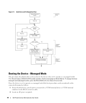
...the connected terminal as follows: 1 Ensure that the device console port is set to a VT100 terminal device or VT100 terminal emulator via the RS-232 crossover cable. 2 Locate an AC power receptacle. 40 Dell PowerConnect 28xx Systems User Guide Managed Mode The procedure described in ...dual purpose Mode Button. Installation and Configuration Flow Connect Device and Console Power On Hardware Setup Press Esc Yes...
...the connected terminal as follows: 1 Ensure that the device console port is set to a VT100 terminal device or VT100 terminal emulator via the RS-232 crossover cable. 2 Locate an AC power receptacle. 40 Dell PowerConnect 28xx Systems User Guide Managed Mode The procedure described in ...dual purpose Mode Button. Installation and Configuration Flow Connect Device and Console Power On Hardware Setup Press Esc Yes...

Getting Started Guide
Page 16
... software. • An RS-232 null-modem cable with Microsoft® Windows 2000, Windows XP, or Windows Vista, ensure that the device console port is connected to www.microsoft.com for monitoring and configuring the device. The PowerConnect 2800 series Console port is set as follows: 1 Ensure that... for information on Windows 2000, Windows XP, and Windows Vista service packs. 3 Connect the female connector of the RS-232 crossover cable directly to the console. To change between managed and unmanaged modes, press the Mode Button for Emulation mode. c Set the data format to 9600 baud...
... software. • An RS-232 null-modem cable with Microsoft® Windows 2000, Windows XP, or Windows Vista, ensure that the device console port is connected to www.microsoft.com for monitoring and configuring the device. The PowerConnect 2800 series Console port is set as follows: 1 Ensure that... for information on Windows 2000, Windows XP, and Windows Vista service packs. 3 Connect the female connector of the RS-232 crossover cable directly to the console. To change between managed and unmanaged modes, press the Mode Button for Emulation mode. c Set the data format to 9600 baud...
Getting Started Guide
Page 17
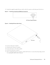
2 Attach the supplied standard AC power cable to the AC receptacle. 6 Activate the AC power receptacle. 7 After activating the AC power receptacle, confirm that the device is connected and operating correctly by examining the LEDs on the back panel of the device. Attaching AC Power cable to device 3 Locate an AC power receptacle. 4 Deactivate the AC power receptacle. 5 Connect the device to the AC connector on the front panel. Figure 3-1. Connecting to PowerConnect 2800 Series Console Port Figure 3-2. Starting and Configuring the Device 15
2 Attach the supplied standard AC power cable to the AC receptacle. 6 Activate the AC power receptacle. 7 After activating the AC power receptacle, confirm that the device is connected and operating correctly by examining the LEDs on the back panel of the device. Attaching AC Power cable to device 3 Locate an AC power receptacle. 4 Deactivate the AC power receptacle. 5 Connect the device to the AC connector on the front panel. Figure 3-1. Connecting to PowerConnect 2800 Series Console Port Figure 3-2. Starting and Configuring the Device 15


