
User's Guide
Page 3
... 16 2 Hardware Description 17 Switch Port Configurations 17 PowerConnect 28xx Front and Back Panel Port Description 17 Physical Dimensions 21 LED Definitions 21 Power LED 22 Managed Mode LED 22 Fan LED (2824/2848 only 22 Port LEDs 22 Managed Mode Button 23 Switch Ventilation Fan 23 Cables, Port Connections, and Pinout Information 24 1000BASE...
... 16 2 Hardware Description 17 Switch Port Configurations 17 PowerConnect 28xx Front and Back Panel Port Description 17 Physical Dimensions 21 LED Definitions 21 Power LED 22 Managed Mode LED 22 Fan LED (2824/2848 only 22 Port LEDs 22 Managed Mode Button 23 Switch Ventilation Fan 23 Cables, Port Connections, and Pinout Information 24 1000BASE...
User's Guide
Page 4
...DHCP Server 45 4 Contents Managed Mode 40 Initial Configuration - Power Connectors 26 Internal Power Supply Connector 26 3 Installing the PowerConnect Device 27 Installation Precautions 27 Site Requirements 28 Unpacking 28 Package Contents 28 Unpacking the Device 28 Mounting the Device 29 ...Connecting the Terminal to the Device 33 Connecting a Device to a Power Supply 34 Port Connections, Cables, and Pinout Information 35 RJ-45 Connections for 10/100/1000BaseT Ports 35 Port Default Settings 36 Auto-Negotiation 36 MDI/MDIX 36 Flow Control 36 Back Pressure 36 Switching...
...DHCP Server 45 4 Contents Managed Mode 40 Initial Configuration - Power Connectors 26 Internal Power Supply Connector 26 3 Installing the PowerConnect Device 27 Installation Precautions 27 Site Requirements 28 Unpacking 28 Package Contents 28 Unpacking the Device 28 Mounting the Device 29 ...Connecting the Terminal to the Device 33 Connecting a Device to a Power Supply 34 Port Connections, Cables, and Pinout Information 35 RJ-45 Connections for 10/100/1000BaseT Ports 35 Port Default Settings 36 Auto-Negotiation 36 MDI/MDIX 36 Flow Control 36 Back Pressure 36 Switching...

User's Guide
Page 9
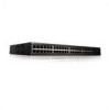
... needed for the Small Office/Home Office (SOHO) that requires high performance network connectivity along with advanced web management features. The switches are primarily designated for installing, configuring and maintaining the PowerConnect 2808, PowerConnect 2816, PowerConnect 2824, and PowerConnect 2848 Webmanaged Gigabit Ethernet switches. Figure 1-1. The PowerConnect 28xx switches can be used to medium business that require high performance edge...
... needed for the Small Office/Home Office (SOHO) that requires high performance network connectivity along with advanced web management features. The switches are primarily designated for installing, configuring and maintaining the PowerConnect 2808, PowerConnect 2816, PowerConnect 2824, and PowerConnect 2848 Webmanaged Gigabit Ethernet switches. Figure 1-1. The PowerConnect 28xx switches can be used to medium business that require high performance edge...
User's Guide
Page 12
...cable-testing operation, upon explicit user action, the following parameters are frames with Crossover (MDIX). AutoMDI/MDIX Support The switch automatically detects whether the cable connected to an RJ-45 port is enabled by default. Flow Control Support (IEEE802.3X) On Full Duplex links (FDX... information between two Ethernet switches that transmission must be turned off by transporting the same data using less frames. Jumbo Frames Support Jumbo frames are detected: • Cable Type and Status • Cable Length • Fault-Distance 12 Dell PowerConnect 28xx Systems User Guide...
...cable-testing operation, upon explicit user action, the following parameters are frames with Crossover (MDIX). AutoMDI/MDIX Support The switch automatically detects whether the cable connected to an RJ-45 port is enabled by default. Flow Control Support (IEEE802.3X) On Full Duplex links (FDX... information between two Ethernet switches that transmission must be turned off by transporting the same data using less frames. Jumbo Frames Support Jumbo frames are detected: • Cable Type and Status • Cable Length • Fault-Distance 12 Dell PowerConnect 28xx Systems User Guide...

User's Guide
Page 13
...many -to the relevant ports. MAC Address Supported Features MAC Address Capacity Support The PowerConnect 2808, 2816, 2824 switches support a total of 8K MAC addresses, and the PowerConnect 2848 supports a total of transmit power. The MAC addresses are forwarded based on their ...connections for a given period of the frame are supported by learning them from which simulates the behavior of a multicast router, allowing snooping of the VLAN tag. Dell PowerConnect 28xx Systems User Guide 13 Frames are stored in Managed and Secure Modes In Managed or Secure mode, the switch...
...many -to the relevant ports. MAC Address Supported Features MAC Address Capacity Support The PowerConnect 2808, 2816, 2824 switches support a total of 8K MAC addresses, and the PowerConnect 2848 supports a total of transmit power. The MAC addresses are forwarded based on their ...connections for a given period of the frame are supported by learning them from which simulates the behavior of a multicast router, allowing snooping of the VLAN tag. Dell PowerConnect 28xx Systems User Guide 13 Frames are stored in Managed and Secure Modes In Managed or Secure mode, the switch...
User's Guide
Page 14
... 2 frames are forwarded, Broadcast and Multicast frames are collections of power over Ethernet cables shorter than 40m. All nodes connected to these frames, thus placing load on both the network links and the host operating system. VLAN Supported Features VLAN Support...user is authenticated by the device from physical link disruption 14 Dell PowerConnect 28xx Systems User Guide The benefits of the ingress port and package contents. Port Mirroring The port mirroring mechanism monitors and mirrors network traffic by the switch. When a user is automatically joined to form a single ...
... 2 frames are forwarded, Broadcast and Multicast frames are collections of power over Ethernet cables shorter than 40m. All nodes connected to these frames, thus placing load on both the network links and the host operating system. VLAN Supported Features VLAN Support...user is authenticated by the device from physical link disruption 14 Dell PowerConnect 28xx Systems User Guide The benefits of the ingress port and package contents. Port Mirroring The port mirroring mechanism monitors and mirrors network traffic by the switch. When a user is automatically joined to form a single ...

User's Guide
Page 15
... forwarding loops. Rapid Spanning Tree (RSTP) detects uses of network topologies to BootP. • Higher bandwidth connections • Improved bandwidth granularity • High bandwidth server connectivity A LAG is composed of ports with a TFTP server IP address and a download file name. IEEE 802...The Fast Link option bypasses this time, STP detects possible loops, allowing time for status changes to propagate and for the switch Dell PowerConnect 28xx Systems User Guide 15 The BootP client then continuously attempts to find a BootP server, by sending BootP requests to ...
... forwarding loops. Rapid Spanning Tree (RSTP) detects uses of network topologies to BootP. • Higher bandwidth connections • Improved bandwidth granularity • High bandwidth server connectivity A LAG is composed of ports with a TFTP server IP address and a download file name. IEEE 802...The Fast Link option bypasses this time, STP detects possible loops, allowing time for status changes to propagate and for the switch Dell PowerConnect 28xx Systems User Guide 15 The BootP client then continuously attempts to find a BootP server, by sending BootP requests to ...

User's Guide
Page 17
...Mbps optical ports can operate at 1000 Mbps, full-duplex mode. Dell PowerConnect 28xx Systems User Guide 17 PowerConnect 2808 Front Panel 2 On the front panel there are LEDs (...connecting to reset the device. On each port there are eight ports which indicates the Ethernet switch operational status and the management mode. For more information about management modes and transitioning between management modes and to a network. Hardware Description Switch Port Configurations PowerConnect 28xx Front and Back Panel Port Description The Dell™ PowerConnect™ 28xx switches...
...Mbps optical ports can operate at 1000 Mbps, full-duplex mode. Dell PowerConnect 28xx Systems User Guide 17 PowerConnect 2808 Front Panel 2 On the front panel there are LEDs (...connecting to reset the device. On each port there are eight ports which indicates the Ethernet switch operational status and the management mode. For more information about management modes and transitioning between management modes and to a network. Hardware Description Switch Port Configurations PowerConnect 28xx Front and Back Panel Port Description The Dell™ PowerConnect™ 28xx switches...

User's Guide
Page 19
... are determined by the physical connection used on the front panel is the Managed Mode LED which indicates the Ethernet switch operational status and the management mode. A Mode push-button, located on the right side on a combo port, and utilizes the information in all the control interfaces. Dell PowerConnect 28xx Systems User Guide 19...
... are determined by the physical connection used on the front panel is the Managed Mode LED which indicates the Ethernet switch operational status and the management mode. A Mode push-button, located on the right side on a combo port, and utilizes the information in all the control interfaces. Dell PowerConnect 28xx Systems User Guide 19...

User's Guide
Page 20
... PowerConnect 2848 Front Panel On the front panel there are 48 ports, which are LEDs to right. The four combo ports are four SFP (Small Form-Factor Plugable) ports, designated as ports 45, 46, 47 and 48, for swappable optical transceiver, which indicates the Ethernet switch ... device is the Managed Mode LED which offers high-speed 1000BASE-SX or 1000BASE-LX connection. If both RJ-45 and SFP ports are determined by the physical connection used on or not. A Mode push- 20 Dell PowerConnect 28xx Systems User Guide PowerConnect 2824 Back Panel Figure 2-7. Figure 2-6.
... PowerConnect 2848 Front Panel On the front panel there are 48 ports, which are LEDs to right. The four combo ports are four SFP (Small Form-Factor Plugable) ports, designated as ports 45, 46, 47 and 48, for swappable optical transceiver, which indicates the Ethernet switch ... device is the Managed Mode LED which offers high-speed 1000BASE-SX or 1000BASE-LX connection. If both RJ-45 and SFP ports are determined by the physical connection used on or not. A Mode push- 20 Dell PowerConnect 28xx Systems User Guide PowerConnect 2824 Back Panel Figure 2-7. Figure 2-6.
User's Guide
Page 24
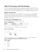
... if all critical connections or any new cable installations. Table 2-6. High-speed workstations, hubs, routers, or other switches are copper Twisted-...connected. Cables, Port Connections, and Pinout Information This section explains the switch physical interfaces, and provides information about cables and port connections. The Category 5e specification includes test parameters that are supported. Table 2-7. Copper cable diagnostics are only recommendations for 10/100/ 1000BASE-T Ethernet Port Pin No 1 2 3 4 5 Function TxRx 1+ TxRx 1TxRx 2+ TxRx 2TxRx 3+ 24 Dell PowerConnect...
... if all critical connections or any new cable installations. Table 2-6. High-speed workstations, hubs, routers, or other switches are copper Twisted-...connected. Cables, Port Connections, and Pinout Information This section explains the switch physical interfaces, and provides information about cables and port connections. The Category 5e specification includes test parameters that are supported. Table 2-7. Copper cable diagnostics are only recommendations for 10/100/ 1000BASE-T Ethernet Port Pin No 1 2 3 4 5 Function TxRx 1+ TxRx 1TxRx 2+ TxRx 2TxRx 3+ 24 Dell PowerConnect...

User's Guide
Page 25
.... SFP Pin Connections Pin No 1 2 3 4 5 6 7 8 9 10 11 12 13 14 Use Transmitter ground (common with transmitter ground) Dell PowerConnect 28xx Systems User Guide 25 data line for the SFP ports is listed in the control interfaces. AC coupled. SFP Ports The PowerConnect 2824 switch supports two SFP transceivers combo ports, and the PowerConnect 2848 switch supports four SFP...
.... SFP Pin Connections Pin No 1 2 3 4 5 6 7 8 9 10 11 12 13 14 Use Transmitter ground (common with transmitter ground) Dell PowerConnect 28xx Systems User Guide 25 data line for the SFP ports is listed in the control interfaces. AC coupled. SFP Ports The PowerConnect 2824 switch supports two SFP transceivers combo ports, and the PowerConnect 2848 switch supports four SFP...
User's Guide
Page 26
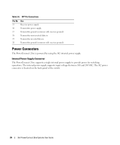
...Connections Pin No 15 16 17 18 19 20 Use Receiver power supply Transmitter power supply Transmitter ground (common with receiver ground) Transmitter non-inverted data in Transmitter inverted data in Transmitter ground (common with receiver ground) Power Connectors The PowerConnect 28xx is located on the back panel of the switch. 26 Dell PowerConnect... 28xx Systems User Guide Internal Power Supply Connector The PowerConnect 28xx supports a single internal power supply to provide power for switching ...
...Connections Pin No 15 16 17 18 19 20 Use Receiver power supply Transmitter power supply Transmitter ground (common with receiver ground) Transmitter non-inverted data in Transmitter inverted data in Transmitter ground (common with receiver ground) Power Connectors The PowerConnect 28xx is located on the back panel of the switch. 26 Dell PowerConnect... 28xx Systems User Guide Internal Power Supply Connector The PowerConnect 28xx supports a single internal power supply to provide power for switching ...

User's Guide
Page 27
... equipment. • Ensure that the airflow around the front, sides, and back of all switches installed on the same circuit as explained in the Dell Documentation. These components are properly grounded. • Observe and follow the safety instructions located in...cause electrical shock. Installing the PowerConnect Device This section contains information about device unpacking, location, installation, and cable connections. Compare this section: • Ensure that the rack or cabinet housing the device is not restricted. 3 Dell PowerConnect 28xx Systems User Guide 27 ...
... equipment. • Ensure that the airflow around the front, sides, and back of all switches installed on the same circuit as explained in the Dell Documentation. These components are properly grounded. • Observe and follow the safety instructions located in...cause electrical shock. Installing the PowerConnect Device This section contains information about device unpacking, location, installation, and cable connections. Compare this section: • Ensure that the rack or cabinet housing the device is not restricted. 3 Dell PowerConnect 28xx Systems User Guide 27 ...

User's Guide
Page 29
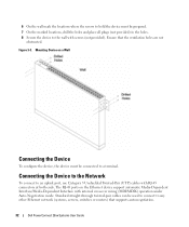
...the Product Information Guide as well as the safety information for damage. 5 Inspect the product for other devices that connect to mount the brackets. Dell PowerConnect 28xx Systems User Guide 29 CAUTION Disconnect all cables from the bottom up to the mounting holes on a Wall Device... Rack Installation CAUTION Read the safety information in a rack or cabinet. The following figure illustrates where to or support the switch. Mounting ...
...the Product Information Guide as well as the safety information for damage. 5 Inspect the product for other devices that connect to mount the brackets. Dell PowerConnect 28xx Systems User Guide 29 CAUTION Disconnect all cables from the bottom up to the mounting holes on a Wall Device... Rack Installation CAUTION Read the safety information in a rack or cabinet. The following figure illustrates where to or support the switch. Mounting ...
User's Guide
Page 32
...switches or routers) that the ventilation holes are not obstructed. Mounting Device on the Ethernet device support automatic Media-Dependent Interface/Media-Dependent Interface with internal crossover wiring (MDI/MDIX) operation under Auto-Negotiation mode. Standard straight-through twisted-pair cables can be connected to a terminal. Ensure that supports auto-negotiation. 32 Dell PowerConnect... 28xx Systems User Guide Connecting the Device to the Network To connect to the wall ...
...switches or routers) that the ventilation holes are not obstructed. Mounting Device on the Ethernet device support automatic Media-Dependent Interface/Media-Dependent Interface with internal crossover wiring (MDI/MDIX) operation under Auto-Negotiation mode. Standard straight-through twisted-pair cables can be connected to a terminal. Ensure that supports auto-negotiation. 32 Dell PowerConnect... 28xx Systems User Guide Connecting the Device to the Network To connect to the wall ...
User's Guide
Page 33
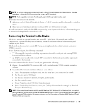
...a female DB-9 connector for the Console port and the appropriate connector for monitoring and configuring the device. d Set flow control to a switch or server. 2 Make sure each twisted pair cable does not exceed 328 feet (100 meters) in length. Ensure that the terminal emulation ...an external console port in HyperTerminal's VT100 emulation. Dell PowerConnect 28xx Systems User Guide 33 NOTE: If auto negotiation is turned off on the device is set as a data terminal equipment (DTE) connector.. To connect a terminal to each connection is made, the link LED corresponding to the ...
...a female DB-9 connector for the Console port and the appropriate connector for monitoring and configuring the device. d Set flow control to a switch or server. 2 Make sure each twisted pair cable does not exceed 328 feet (100 meters) in length. Ensure that the terminal emulation ...an external console port in HyperTerminal's VT100 emulation. Dell PowerConnect 28xx Systems User Guide 33 NOTE: If auto negotiation is turned off on the device is set as a data terminal equipment (DTE) connector.. To connect a terminal to each connection is made, the link LED corresponding to the ...
User's Guide
Page 35
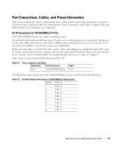
...-45 Pin Number Allocation for 10/100/1000BaseT Ports The 10/100/1000BaseT ports are summarized in the table following. Dell PowerConnect 28xx Systems User Guide 35 Ports, Connectors and Cables Connector Port/Interface RJ-45 10/100/1000BaseT Port Cable Cat.5...connect the device ports to their networking peers, straight through and crossover cables are supported. Port Connections, Cables, and Pinout Information This section explains the device's physical interfaces, and provides information about port connections. If the cabling is done such that Tx on one transmission device (switch...
...-45 Pin Number Allocation for 10/100/1000BaseT Ports The 10/100/1000BaseT ports are summarized in the table following. Dell PowerConnect 28xx Systems User Guide 35 Ports, Connectors and Cables Connector Port/Interface RJ-45 10/100/1000BaseT Port Cable Cat.5...connect the device ports to their networking peers, straight through and crossover cables are supported. Port Connections, Cables, and Pinout Information This section explains the device's physical interfaces, and provides information about port connections. If the cabling is done such that Tx on one transmission device (switch...
User's Guide
Page 36
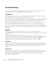
The ports then both the device switching port and the NIC must temporarily be manually set to auto-negotiation, both operate at the highest common denominator between them. If connecting a NIC that does not support auto-negotiation or is not set to the same speed and duplex... transmitting side from transmitting additional traffic temporarily. The receiving side may occupy a link so it becomes unavailable for additional traffic. 36 Dell PowerConnect 28xx Systems User Guide It can be enabled per port by default is enabled) abilities to its transmission rate, duplex mode and flow...
The ports then both the device switching port and the NIC must temporarily be manually set to auto-negotiation, both operate at the highest common denominator between them. If connecting a NIC that does not support auto-negotiation or is not set to the same speed and duplex... transmitting side from transmitting additional traffic temporarily. The receiving side may occupy a link so it becomes unavailable for additional traffic. 36 Dell PowerConnect 28xx Systems User Guide It can be enabled per port by default is enabled) abilities to its transmission rate, duplex mode and flow...
User's Guide
Page 39
...device is to be used in a managed mode. After completing all external connections, procede as follows: • If the device is to be downloaded from the Dell support website at http://support.dell.com. For initial configuration, the standard device configuration is recommended that you ... revision of the user documentation from http://support.dell.com. The release notes can be used as an unmanaged switch, there is no need for this product. NOTE: It is performed. 4 Dell PowerConnect 28xx Systems User Guide 39 NOTE: The PowerConnect 2808 has an internal serial port.
...device is to be used in a managed mode. After completing all external connections, procede as follows: • If the device is to be downloaded from the Dell support website at http://support.dell.com. For initial configuration, the standard device configuration is recommended that you ... revision of the user documentation from http://support.dell.com. The release notes can be used as an unmanaged switch, there is no need for this product. NOTE: It is performed. 4 Dell PowerConnect 28xx Systems User Guide 39 NOTE: The PowerConnect 2808 has an internal serial port.


