Quick Reference Guide
Page 9
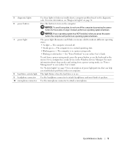
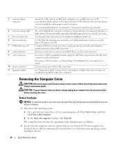
...or the mouse if it is configured as a wake device in the Windows Device Manager. This light flickers when the hard drive is in a power-saving mode. • Blinking or solid amber - NOTICE: To avoid losing data, do not turn on the diagnostic code. Instead, perform an... operating system shutdown. The computer is in a normal operating state. • Blinking green - See "Power Problems" in your online User's Guide. NOTICE: If your operating system has ACPI enabled, when you troubleshoot problems with your online User's Guide. The ...
...or the mouse if it is configured as a wake device in the Windows Device Manager. This light flickers when the hard drive is in a power-saving mode. • Blinking or solid amber - NOTICE: To avoid losing data, do not turn on the diagnostic code. Instead, perform an... operating system shutdown. The computer is in a normal operating state. • Blinking green - See "Power Problems" in your online User's Guide. NOTICE: If your operating system has ACPI enabled, when you troubleshoot problems with your online User's Guide. The ...
Quick Reference Guide
Page 10
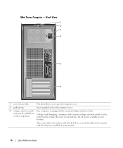
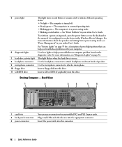
.... 3 voltage selection switch Your computer is equipped with a manual voltage-selection switch. (may not be available on To help avoid damaging a computer with the AC power available in your location. 10 Quick Reference Guide Mini Tower Computer - Back View 1 2 3 4 5 6 1 cover release latch This latch allows you to open the computer cover.... 2 padlock ring Insert a padlock to operate with a manual voltage-selection switch, set the certain computers) switch for the voltage that most closely matches the AC power available in your location.
.... 3 voltage selection switch Your computer is equipped with a manual voltage-selection switch. (may not be available on To help avoid damaging a computer with the AC power available in your location. 10 Quick Reference Guide Mini Tower Computer - Back View 1 2 3 4 5 6 1 cover release latch This latch allows you to open the computer cover.... 2 padlock ring Insert a padlock to operate with a manual voltage-selection switch, set the certain computers) switch for the voltage that most closely matches the AC power available in your location.
Quick Reference Guide
Page 11
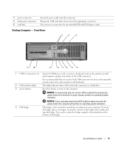
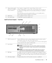
... USB devices such as printers and keyboards. 2 LAN indicator light This light indicates that you press the power button the computer will perform an operating system shutdown. 4 Dell badge The badge can also rotate the badge using the slot provided near the bottom of the USB connectors...Guide 11 It is recommended that a LAN (network) connection is established. 3 power button Press this connector. NOTICE: If your computer. 4 power connector 5 back-panel connectors 6 card slots Insert the power cable into the appropriate connector. You can be rotated to turn on the computer...
... USB devices such as printers and keyboards. 2 LAN indicator light This light indicates that you press the power button the computer will perform an operating system shutdown. 4 Dell badge The badge can also rotate the badge using the slot provided near the bottom of the USB connectors...Guide 11 It is recommended that a LAN (network) connection is established. 3 power button Press this connector. NOTICE: If your computer. 4 power connector 5 back-panel connectors 6 card slots Insert the power cable into the appropriate connector. You can be rotated to turn on the computer...
Quick Reference Guide
Page 12
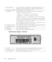
...you troubleshoot a computer problem based on the diagnostic code. Back View 1 2 3 4 5 6 1 card slots 2 back-panel connectors 3 power connector You can help you troubleshoot problems with your computer. Use the microphone connector to indicate different operating states: • No light - Desktop Computer... - Insert the power cable into this connector. 12 Quick Reference Guide See "System Lights" on page 35 for any installed PCI and PCI ...
...you troubleshoot a computer problem based on the diagnostic code. Back View 1 2 3 4 5 6 1 card slots 2 back-panel connectors 3 power connector You can help you troubleshoot problems with your computer. Use the microphone connector to indicate different operating states: • No light - Desktop Computer... - Insert the power cable into this connector. 12 Quick Reference Guide See "System Lights" on page 35 for any installed PCI and PCI ...
Quick Reference Guide
Page 13
... are electrically rated to operate with a manual voltage-selection switch, set certain computers) the switch for devices that most closely matches the AC power available in your location. 5 padlock ring Insert a padlock to lock the computer cover. 6 cover release latch Use this button to turn ... the badge, place fingers around the outside of the USB connectors. This light indicates that you press the power button the computer will perform an operating system shutdown. 3 Dell badge 4 LAN indicator light The badge can also rotate the badge using the slot provided near the bottom ...
... are electrically rated to operate with a manual voltage-selection switch, set certain computers) the switch for devices that most closely matches the AC power available in your location. 5 padlock ring Insert a padlock to lock the computer cover. 6 cover release latch Use this button to turn ... the badge, place fingers around the outside of the USB connectors. This light indicates that you press the power button the computer will perform an operating system shutdown. 3 Dell badge 4 LAN indicator light The badge can also rotate the badge using the slot provided near the bottom ...
Quick Reference Guide
Page 14
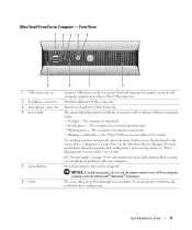
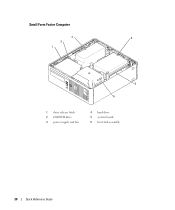
... can access connectors for a description of speakers. Small Form Factor Computer - For more information about sleep modes and exiting from a power-saving mode, press the power button or use . The computer is in use the keyboard or the mouse if it is in the Windows Device Manager. Insert ...a CD or DVD (if applicable) into the appropriate connector. Connect the power cable to attach a microphone. Turns on and blinks or remains solid to help you troubleshoot a computer problem based on page 36. Plug serial,...
... can access connectors for a description of speakers. Small Form Factor Computer - For more information about sleep modes and exiting from a power-saving mode, press the power button or use . The computer is in use the keyboard or the mouse if it is in the Windows Device Manager. Insert ...a CD or DVD (if applicable) into the appropriate connector. Connect the power cable to attach a microphone. Turns on and blinks or remains solid to help you troubleshoot a computer problem based on page 36. Plug serial,...
Quick Reference Guide
Page 15
... voltage-selection switch, set certain computers) the switch for the voltage that your monitor and attached devices are electrically rated to operate with the AC power available in your location. 5 padlock ring Insert a padlock to lock the computer cover. 6 cover release latch Use this latch to the network. The computer is...
... voltage-selection switch, set certain computers) the switch for the voltage that your monitor and attached devices are electrically rated to operate with the AC power available in your location. 5 padlock ring Insert a padlock to lock the computer cover. 6 cover release latch Use this latch to the network. The computer is...
Quick Reference Guide
Page 17
...do not use the keyboard or the mouse if it is turned off the computer. Quick Reference Guide 17 The computer is in a power-saving mode. • Blinking or solid yellow- Press this button to flow through your online User's Guide. Instead, perform a ...shutdown. For more information about sleep modes and exiting from a power-saving mode, press the power button or use the power button to indicate different operating states: • No light - Attach headphones to this connector. See "Power Problems" in your computer. Attach a microphone to this connector...
...do not use the keyboard or the mouse if it is turned off the computer. Quick Reference Guide 17 The computer is in a power-saving mode. • Blinking or solid yellow- Press this button to flow through your online User's Guide. Instead, perform a ...shutdown. For more information about sleep modes and exiting from a power-saving mode, press the power button or use the power button to indicate different operating states: • No light - Attach headphones to this connector. See "Power Problems" in your computer. Attach a microphone to this connector...
Quick Reference Guide
Page 19
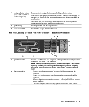
Connect the power cable to flow through your computer. The vents allow air to this connector. If you have a USB printer, plug it into a USB connector. • Green - A ... ensure proper ventilation, do not block these cooling vents. A good connection exists between a 1000-Mbps (1-Gbps) network and the computer. • Off - 3 back-panel connectors 4 power connector 5 vents See the following subsection, "Ultra-Small Form Factor Computer - Back-Panel Connectors 1 2 3 4 5 6 11 10 1 parallel connector 2 link integrity light 9 8 7 Connect a parallel device, such...
Connect the power cable to flow through your computer. The vents allow air to this connector. If you have a USB printer, plug it into a USB connector. • Green - A ... ensure proper ventilation, do not block these cooling vents. A good connection exists between a 1000-Mbps (1-Gbps) network and the computer. • Off - 3 back-panel connectors 4 power connector 5 vents See the following subsection, "Ultra-Small Form Factor Computer - Back-Panel Connectors 1 2 3 4 5 6 11 10 1 parallel connector 2 link integrity light 9 8 7 Connect a parallel device, such...
Quick Reference Guide
Page 20
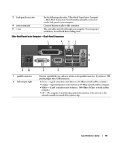
... 5 line-out connector 6 line-in connector to attach a record/playback device such as a cassette player, CD player, or VCR. Connect the power cable to the serial connector. Connect USB devices such as a mouse, keyboard, printer, joystick, and computer speakers into place. Use the blue line...-in connector 7 USB connectors (5) 8 serial connector 9 video connector 10 power connector 11 diagnostic lights Attach the UTP cable to an RJ45 jack wall plate or to attach an amplified speaker set. If your computer and...
... 5 line-out connector 6 line-in connector to attach a record/playback device such as a cassette player, CD player, or VCR. Connect the power cable to the serial connector. Connect USB devices such as a mouse, keyboard, printer, joystick, and computer speakers into place. Use the blue line...-in connector 7 USB connectors (5) 8 serial connector 9 video connector 10 power connector 11 diagnostic lights Attach the UTP cable to an RJ45 jack wall plate or to attach an amplified speaker set. If your computer and...
Quick Reference Guide
Page 21
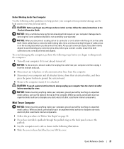
... your own personal safety. CAUTION: Before you connect a cable, ensure that is not authorized by Dell is not already turned off your computer and all attached devices from their electrical outlets, and then press the power button to servicing that both connectors are disconnecting this section, follow the safety instructions in on...
... your own personal safety. CAUTION: Before you connect a cable, ensure that is not authorized by Dell is not already turned off your computer and all attached devices from their electrical outlets, and then press the power button to servicing that both connectors are disconnecting this section, follow the safety instructions in on...

Quick Reference Guide
Page 27
Desktop Computer 2 1 3 4 5 7 6 1 drives bay (CD/DVD, floppy, and hard drive) 2 power supply 3 chassis intrusion switch 4 system board 5 card slots (3) for one PCI Express x16 card and two PCI cards 6 heat sink assembly 7 front I/O panel Quick Reference Guide 27
Desktop Computer 2 1 3 4 5 7 6 1 drives bay (CD/DVD, floppy, and hard drive) 2 power supply 3 chassis intrusion switch 4 system board 5 card slots (3) for one PCI Express x16 card and two PCI cards 6 heat sink assembly 7 front I/O panel Quick Reference Guide 27
Quick Reference Guide
Page 28
Small Form Factor Computer 3 4 2 1 5 6 1 drive release latch 2 CD/DVD drive 3 power supply and fan 4 hard drive 5 system board 6 heat sink assembly 28 Quick Reference Guide
Small Form Factor Computer 3 4 2 1 5 6 1 drive release latch 2 CD/DVD drive 3 power supply and fan 4 hard drive 5 system board 6 heat sink assembly 28 Quick Reference Guide
Quick Reference Guide
Page 30
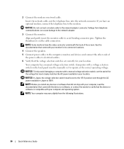
... pins. Tighten the thumbscrews on the back panel must be manually set the switch for its connector locations. 4 Connect the speakers. 5 Connect power cables to the network adapter. 3 Connect the monitor. Your computer has a manual voltage-selection switch. Insert the network cable, not the telephone...In Japan, the voltage selection switch must be set correctly for your location. See the documentation that most closely matches the AC power available in Japan is compatible with your monitor for the voltage that came with the device or software, or contact the vendor to...
... pins. Tighten the thumbscrews on the back panel must be manually set the switch for its connector locations. 4 Connect the speakers. 5 Connect power cables to the network adapter. 3 Connect the monitor. Your computer has a manual voltage-selection switch. Insert the network cable, not the telephone...In Japan, the voltage selection switch must be set correctly for your location. See the documentation that most closely matches the AC power available in Japan is compatible with your monitor for the voltage that came with the device or software, or contact the vendor to...
Quick Reference Guide
Page 32
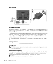
... Guide. See "Finding Information" on contacting Dell, see your computer, see the Dell Support website at support.dell.com. Express Service Code Service Tag: Dell Diagnostics CAUTION: Before you if your online User's Guide. Power Connections Solving Problems Dell provides a number of tools to Use the Dell Diagnostics If you contact Dell for your online User's Guide. If...
... Guide. See "Finding Information" on contacting Dell, see your computer, see the Dell Support website at support.dell.com. Express Service Code Service Tag: Dell Diagnostics CAUTION: Before you if your online User's Guide. Power Connections Solving Problems Dell provides a number of tools to Use the Dell Diagnostics If you contact Dell for your online User's Guide. If...
Quick Reference Guide
Page 35
... computer. No corrective action is not identified, contact Dell for technical assistance. Solid yellow The Dell Diagnostics is identified. and no video during POST Solid green power light and no beep code be faulty or incorrectly installed. See "Power Problems" in a power-saving mode. Solid green power The monitor or the graphics card may Check "Diagnostic...
... computer. No corrective action is not identified, contact Dell for technical assistance. Solid yellow The Dell Diagnostics is identified. and no video during POST Solid green power light and no beep code be faulty or incorrectly installed. See "Power Problems" in a power-saving mode. Solid green power The monitor or the graphics card may Check "Diagnostic...
Quick Reference Guide
Page 36
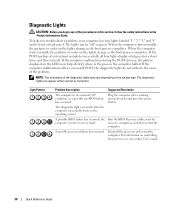
... the lights change as the boot process completes. To help identify where in a normal "off . Plug the computer into a working electrical outlet and press the power button. The diagnostic lights are not lit after a successful POST, the diagnostic lights do not indicate the cause of system boot completes successfully, all four...
... the lights change as the boot process completes. To help identify where in a normal "off . Plug the computer into a working electrical outlet and press the power button. The diagnostic lights are not lit after a successful POST, the diagnostic lights do not indicate the cause of system boot completes successfully, all four...
Quick Reference Guide
Page 37
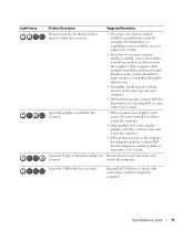
For information on contacting Dell, see your online User's Guide. For information on reinstalling memory modules, see your online User's Guide. Continue until you have identified a faulty module or ...computer. • If the problem persists or the computer has integrated graphics, contact Dell. For information on contacting Dell, see your computer. • If the problem persists, contact Dell. restart the computer. A possible floppy or hard drive failure has Reseat all power and data cables and occurred. A possible graphics card failure has occurred. •...
For information on contacting Dell, see your online User's Guide. For information on reinstalling memory modules, see your online User's Guide. Continue until you have identified a faulty module or ...computer. • If the problem persists or the computer has integrated graphics, contact Dell. For information on contacting Dell, see your computer. • If the problem persists, contact Dell. restart the computer. A possible floppy or hard drive failure has Reseat all power and data cables and occurred. A possible graphics card failure has occurred. •...
Quick Reference Guide
Page 39
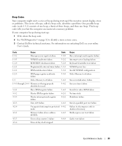
... of -day clock stopped Cause Slave interrupt mask register failure Interrupt vector loading failure Keyboard Controller test failure NVRAM power loss Invalid NVRAM configuration Video Memory test failure Screen initialization failure Screen retrace failure Search for technical assistance. This ... Beep Codes Your computer might emit a series of beeps during start -up : 1 Write down the beep code. 2 See "Dell Diagnostics" on contacting Dell, see your online User's Guide. Code Cause Code 1-1-2 Microprocessor register failure 3-1-4 1-1-3 NVRAM read/write failure 3-2-2 1-1-4 ROM BIOS ...
... of -day clock stopped Cause Slave interrupt mask register failure Interrupt vector loading failure Keyboard Controller test failure NVRAM power loss Invalid NVRAM configuration Video Memory test failure Screen initialization failure Screen retrace failure Search for technical assistance. This ... Beep Codes Your computer might emit a series of beeps during start -up : 1 Write down the beep code. 2 See "Dell Diagnostics" on contacting Dell, see your online User's Guide. Code Cause Code 1-1-2 Microprocessor register failure 3-1-4 1-1-3 NVRAM read/write failure 3-2-2 1-1-4 ROM BIOS ...
Quick Reference Guide
Page 47
... labels Microsoft Windows, 6 Service Tag, 6 M Microsoft Windows label, 6 E error messages beep codes, 39 H hardware beep codes, 39 conflicts, 40 Dell Diagnostics, 32 Hardware Troubleshooter, 40 Help and Support Center, 7 I installing parts before you begin, 20 IRQ conflicts, 40 O operating system CD, 7 ...Installation Guide, 7 reinstalling Windows XP, 42 Operating System CD, 7 P power light diagnosing problems with, 35 locations, 9, 12, 14, 17 problems beep codes, 39 conflicts, 40 Dell Diagnostics, 32 restore computer to previous operating state, 40 Index 47
... labels Microsoft Windows, 6 Service Tag, 6 M Microsoft Windows label, 6 E error messages beep codes, 39 H hardware beep codes, 39 conflicts, 40 Dell Diagnostics, 32 Hardware Troubleshooter, 40 Help and Support Center, 7 I installing parts before you begin, 20 IRQ conflicts, 40 O operating system CD, 7 ...Installation Guide, 7 reinstalling Windows XP, 42 Operating System CD, 7 P power light diagnosing problems with, 35 locations, 9, 12, 14, 17 problems beep codes, 39 conflicts, 40 Dell Diagnostics, 32 restore computer to previous operating state, 40 Index 47


