Quick Reference Guide
Page 3
... Factor Computer 25 Inside Your Computer 26 Mini Tower Computer 26 Desktop Computer 27 Small Form Factor Computer 28 Ultra-Small Form Factor Computer 29 Setting Up Your Computer 29 Solving Problems 32 Dell Diagnostics 32 System Lights 35 Diagnostic Lights 36 Beep Codes 39 Running the Dell™ IDE Hard Drive Diagnostics 40 Resolving Software and Hardware Incompatibilities 40 Using Microsoft® Windows® XP System Restore 40 Reinstalling Microsoft...
... Factor Computer 25 Inside Your Computer 26 Mini Tower Computer 26 Desktop Computer 27 Small Form Factor Computer 28 Ultra-Small Form Factor Computer 29 Setting Up Your Computer 29 Solving Problems 32 Dell Diagnostics 32 System Lights 35 Diagnostic Lights 36 Beep Codes 39 Running the Dell™ IDE Hard Drive Diagnostics 40 Resolving Software and Hardware Incompatibilities 40 Using Microsoft® Windows® XP System Restore 40 Reinstalling Microsoft...
Quick Reference Guide
Page 5
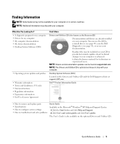
...; Safety instructions • Regulatory information • Ergonomics information • End User License Agreement Find It Here Drivers and Utilities CD (also known as the ResourceCD) Documentation and drivers are already installed on the optional Drivers and Utilities CD. Dell™ Product Information Guide • How to remove and replace parts • Specifications • How to configure system settings • How to reinstall drivers (see page 44), run the Dell Diagnostics (see...
...; Safety instructions • Regulatory information • Ergonomics information • End User License Agreement Find It Here Drivers and Utilities CD (also known as the ResourceCD) Documentation and drivers are already installed on the optional Drivers and Utilities CD. Dell™ Product Information Guide • How to remove and replace parts • Specifications • How to configure system settings • How to reinstall drivers (see page 44), run the Dell Diagnostics (see...
Quick Reference Guide
Page 6
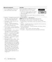
... are located on computer configuration, product specifications, and white papers • Downloads - Hints and tips, articles from technicians, online NOTE: Select your Dell computer. Drivers, patches, and software updates • Service and support - If you use support.dell.com or contact technical support. • Enter the Express Service Code to direct your computer when you reinstall the operating system for Dell™ 3.5-inch USB floppy drives, Intel® Pentium® M processors, optical drives, and USB devices. This software...
... are located on computer configuration, product specifications, and white papers • Downloads - Hints and tips, articles from technicians, online NOTE: Select your Dell computer. Drivers, patches, and software updates • Service and support - If you use support.dell.com or contact technical support. • Enter the Express Service Code to direct your computer when you reinstall the operating system for Dell™ 3.5-inch USB floppy drives, Intel® Pentium® M processors, optical drives, and USB devices. This software...
Quick Reference Guide
Page 8
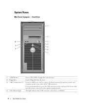
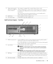
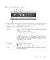
... 3 4 9 5 8 6 7 1 CD/DVD drive Insert a CD or DVD (if applicable) into this drive. 2 floppy drive Insert a floppy disk into this drive. 3 USB 2.0 connectors (2) Connect USB devices such as printers and keyboards. 4 LAN indicator light This light indicates that a LAN (network) connection is recommended that you use the USB connectors on the back panel for devices that typically remain connected, such as a mouse, keyboard, memory key, printer, joystick, and computer speakers into either of the USB connectors. It is established. 8 Quick Reference Guide System Views...
... 3 4 9 5 8 6 7 1 CD/DVD drive Insert a CD or DVD (if applicable) into this drive. 2 floppy drive Insert a floppy disk into this drive. 3 USB 2.0 connectors (2) Connect USB devices such as printers and keyboards. 4 LAN indicator light This light indicates that a LAN (network) connection is recommended that you use the USB connectors on the back panel for devices that typically remain connected, such as a mouse, keyboard, memory key, printer, joystick, and computer speakers into either of the USB connectors. It is established. 8 Quick Reference Guide System Views...
Quick Reference Guide
Page 9
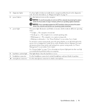
... power light patterns that can help you troubleshoot a computer problem based on page 36. To exit from a power-saving mode, see "Diagnostic Lights" on the diagnostic code. The power light illuminates and blinks or remains solid to indicate different operating states: • No light - 5 diagnostic lights 6 power button 7 power light 8 hard-drive activity light 9 headphone connector 10 microphone connector Use these lights to help you troubleshoot problems with your online User's Guide. For more information about sleep modes and exiting from a power-saving mode, press the power...
... power light patterns that can help you troubleshoot a computer problem based on page 36. To exit from a power-saving mode, see "Diagnostic Lights" on the diagnostic code. The power light illuminates and blinks or remains solid to indicate different operating states: • No light - 5 diagnostic lights 6 power button 7 power light 8 hard-drive activity light 9 headphone connector 10 microphone connector Use these lights to help you troubleshoot problems with your online User's Guide. For more information about sleep modes and exiting from a power-saving mode, press the power...
Quick Reference Guide
Page 10
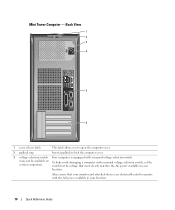
... matches the AC power available in your location. Mini Tower Computer - Back View 1 2 3 4 5 6 1 cover release latch This latch allows you to open the computer cover. 2 padlock ring Insert a padlock to operate with a manual voltage-selection switch, set the certain computers) switch for the voltage that your monitor and attached devices are electrically rated to lock the computer cover. 3 voltage selection switch Your computer is...
... matches the AC power available in your location. Mini Tower Computer - Back View 1 2 3 4 5 6 1 cover release latch This latch allows you to open the computer cover. 2 padlock ring Insert a padlock to operate with a manual voltage-selection switch, set the certain computers) switch for the voltage that your monitor and attached devices are electrically rated to lock the computer cover. 3 voltage selection switch Your computer is...
Quick Reference Guide
Page 11
... rotate the badge, place your operating system has ACPI enabled, when you use the back USB connectors for devices that typically remain connected, such as a mouse, keyboard, memory key, printer, joystick, and computer speakers into the appropriate connector. 4 power connector 5 back-panel connectors 6 card slots Insert the power cable into this button to match the orientation of the badge, press firmly, and turn off the computer by pressing the power button for any installed PCI and PCI Express cards.
... rotate the badge, place your operating system has ACPI enabled, when you use the back USB connectors for devices that typically remain connected, such as a mouse, keyboard, memory key, printer, joystick, and computer speakers into the appropriate connector. 4 power connector 5 back-panel connectors 6 card slots Insert the power cable into this button to match the orientation of the badge, press firmly, and turn off the computer by pressing the power button for any installed PCI and PCI Express cards.
Quick Reference Guide
Page 12
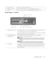
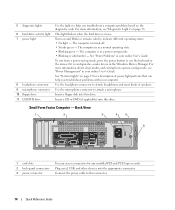
...4 5 6 1 card slots 2 back-panel connectors 3 power connector You can help you troubleshoot problems with your computer. See "Power Problems" in your online User's Guide. Insert a floppy disk into this drive. 5 power light 6 diagnostic lights 7 hard-drive activity light 8 headphone connector 9 microphone connector 10 floppy drive 11 CD/DVD drive This light turns on and blinks or remains solid to attach a microphone. The computer is configured as a wake device in a normal operating state. • Blinking green - The computer is in the Windows Device Manager. See...
...4 5 6 1 card slots 2 back-panel connectors 3 power connector You can help you troubleshoot problems with your computer. See "Power Problems" in your online User's Guide. Insert a floppy disk into this drive. 5 power light 6 diagnostic lights 7 hard-drive activity light 8 headphone connector 9 microphone connector 10 floppy drive 11 CD/DVD drive This light turns on and blinks or remains solid to attach a microphone. The computer is configured as a wake device in a normal operating state. • Blinking green - The computer is in the Windows Device Manager. See...
Quick Reference Guide
Page 13
.... This light indicates that a LAN (network) connection is established. Also, ensure that your monitor and attached devices are electrically rated to operate with a manual voltage-selection switch, set certain computers) the switch for the voltage that most closely matches the AC power available in your location. 5 padlock ring Insert a padlock to lock the computer cover. 6 cover release latch Use this button to match the orientation of the USB connectors...
.... This light indicates that a LAN (network) connection is established. Also, ensure that your monitor and attached devices are electrically rated to operate with a manual voltage-selection switch, set certain computers) the switch for the voltage that most closely matches the AC power available in your location. 5 padlock ring Insert a padlock to lock the computer cover. 6 cover release latch Use this button to match the orientation of the USB connectors...
Quick Reference Guide
Page 14
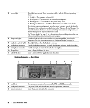
... solid to attach a microphone. Small Form Factor Computer - To exit from a power-saving mode, see "Diagnostic Lights" on page 35 for any installed PCI and PCI Express cards. Use the microphone connector to indicate different operating states: • No light - Insert a CD or DVD (if applicable) into the appropriate connector. Back View 1 2 3 4 5 6 1 card slots 2 back-panel connectors 3 power connector You can help you troubleshoot problems with your computer. Plug serial, USB, and other devices into this drive.
... solid to attach a microphone. Small Form Factor Computer - To exit from a power-saving mode, see "Diagnostic Lights" on page 35 for any installed PCI and PCI Express cards. Use the microphone connector to indicate different operating states: • No light - Insert a CD or DVD (if applicable) into the appropriate connector. Back View 1 2 3 4 5 6 1 card slots 2 back-panel connectors 3 power connector You can help you troubleshoot problems with your computer. Plug serial, USB, and other devices into this drive.
Quick Reference Guide
Page 15
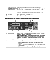
... installed card containing a parallel connector configured to the same address. A good connection exists between a 10-Mbps network and the computer. • Orange - Quick Reference Guide 15 If you have a USB printer, plug it into a USB connector. NOTE: The integrated parallel connector is not detecting a physical connection to the network. Back-Panel Connectors 1 2 34 5 6 7 10 1 parallel connector 2 link integrity light 9 8 Connect a parallel device, such as a printer, to the parallel connector. 4 voltage selection switch...
... installed card containing a parallel connector configured to the same address. A good connection exists between a 10-Mbps network and the computer. • Orange - Quick Reference Guide 15 If you have a USB printer, plug it into a USB connector. NOTE: The integrated parallel connector is not detecting a physical connection to the network. Back-Panel Connectors 1 2 34 5 6 7 10 1 parallel connector 2 link integrity light 9 8 Connect a parallel device, such as a printer, to the parallel connector. 4 voltage selection switch...

Quick Reference Guide
Page 16
...a network adapter card, use the y-cable that the network cable has been securely attached. Do not remove the cap. On computers with your computer. This light flashes a yellow light when the computer is on the card. Connect your monitor to be covered by a cap. 3 network adapter connector 4 network activity light 5 line-in connector 6 line-out connector 7 microphone connector 8 USB 2.0 connectors (6) 9 video connector 10 serial connector To attach your computer to a network or broadband device, connect one end of your computer. Connect USB devices such as a mouse, keyboard, memory...
...a network adapter card, use the y-cable that the network cable has been securely attached. Do not remove the cap. On computers with your computer. This light flashes a yellow light when the computer is on the card. Connect your monitor to be covered by a cap. 3 network adapter connector 4 network activity light 5 line-in connector 6 line-out connector 7 microphone connector 8 USB 2.0 connectors (6) 9 video connector 10 serial connector To attach your computer to a network or broadband device, connect one end of your computer. Connect USB devices such as a mouse, keyboard, memory...
Quick Reference Guide
Page 17
... 1 23 4 5 9 1 USB connectors (2) 2 headphone connector 3 microphone connector 4 power light 5 power button 6 vents 8 7 6 Connect USB devices such as a wake device in your computer. The vents allow air to turn off . • Steady green - The computer is configured as a mouse, keyboard, memory key, printer, joystick, and computer speakers into either of power light patterns that can help you troubleshoot problems with your online User's Guide. See "System Lights" on the computer. To exit from a power-saving mode, see "Power Management" in the Windows Device Manager.
... 1 23 4 5 9 1 USB connectors (2) 2 headphone connector 3 microphone connector 4 power light 5 power button 6 vents 8 7 6 Connect USB devices such as a wake device in your computer. The vents allow air to turn off . • Steady green - The computer is configured as a mouse, keyboard, memory key, printer, joystick, and computer speakers into either of power light patterns that can help you troubleshoot problems with your online User's Guide. See "System Lights" on the computer. To exit from a power-saving mode, see "Power Management" in the Windows Device Manager.
Quick Reference Guide
Page 20
... User's Guide. If you begin any of the procedures in this connector. Removing the Computer Cover CAUTION: Before you have a VGA monitor, see "Connecting a VGA Monitor" in the Product Information Guide. Connect the power cable to this section, follow the safety instructions in your computer. 1 Shut down your operating system, turn off now. 20 Quick Reference Guide 3 network adapter connector 4 network activity light 5 line-out connector 6 line-in connector 7 USB connectors (5) 8 serial connector 9 video connector 10 power connector 11 diagnostic lights Attach the UTP cable...
... User's Guide. If you begin any of the procedures in this connector. Removing the Computer Cover CAUTION: Before you have a VGA monitor, see "Connecting a VGA Monitor" in the Product Information Guide. Connect the power cable to this section, follow the safety instructions in your computer. 1 Shut down your operating system, turn off now. 20 Quick Reference Guide 3 network adapter connector 4 network activity light 5 line-out connector 6 line-in connector 7 USB connectors (5) 8 serial connector 9 video connector 10 power connector 11 diagnostic lights Attach the UTP cable...
Quick Reference Guide
Page 30
... the voltage selection switch is set the switch for its connector locations. 4 Connect the speakers. 5 Connect power cables to the computer, monitor, and devices and connect the other ends of the screen. 2 Connect the modem or network cable. NOTICE: Do not connect a modem cable to operate at the correct operating voltage. Voltage from the following illustrations. 30 Quick Reference Guide NOTE: Before you have the video connector underneath the back of the power cables to the...
... the voltage selection switch is set the switch for its connector locations. 4 Connect the speakers. 5 Connect power cables to the computer, monitor, and devices and connect the other ends of the screen. 2 Connect the modem or network cable. NOTICE: Do not connect a modem cable to operate at the correct operating voltage. Voltage from the following illustrations. 30 Quick Reference Guide NOTE: Before you have the video connector underneath the back of the power cables to the...
Quick Reference Guide
Page 34
... contact Dell, technical support will ask for your hardware configuration for the selected device. Describes the test and may not display the names of all the components installed on your computer or all devices from the Drivers and Utilities CD (optional), remove the CD. 34 Quick Reference Guide The device list may indicate requirements for running the Dell Diagnostics from system setup, memory, and various internal tests, and it displays the information in the device list in...
... contact Dell, technical support will ask for your hardware configuration for the selected device. Describes the test and may not display the names of all the components installed on your computer or all devices from the Drivers and Utilities CD (optional), remove the CD. 34 Quick Reference Guide The device list may indicate requirements for running the Dell Diagnostics from system setup, memory, and various internal tests, and it displays the information in the device list in...
Quick Reference Guide
Page 35
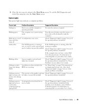
... does not boot, contact Dell for instructions on diagnosing the beep code. Blinking yellow A power supply or system board failure has occurred. See "Beep Codes" on page 36 to complete. Check "Diagnostic Lights" on page 39 for technical assistance. Quick Reference Guide 35 System Lights Your power light may be faulty. Blinking green The computer is in your online User's Guide. If the Dell Diagnostics is running a test, or a device on contacting Dell, see if the specific problem is identified...
... does not boot, contact Dell for instructions on diagnosing the beep code. Blinking yellow A power supply or system board failure has occurred. See "Beep Codes" on page 36 to complete. Check "Diagnostic Lights" on page 39 for technical assistance. Quick Reference Guide 35 System Lights Your power light may be faulty. Blinking green The computer is in your online User's Guide. If the Dell Diagnostics is running a test, or a device on contacting Dell, see if the specific problem is identified...
Quick Reference Guide
Page 38
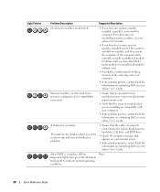
... no special memory module/memory connector placement requirements exist. • Verify that the memory modules that appears on contacting Dell, see your online User's Guide. Continue until you have identified a faulty module or reinstalled all four diagnostic lights turn green briefly before turning off to the system board from the hard drive, CD drive, and DVD drive. • Check the computer message that you are installing are detected...
... no special memory module/memory connector placement requirements exist. • Verify that the memory modules that appears on contacting Dell, see your online User's Guide. Continue until you have identified a faulty module or reinstalled all four diagnostic lights turn green briefly before turning off to the system board from the hard drive, CD drive, and DVD drive. • Check the computer message that you are installing are detected...
Quick Reference Guide
Page 40
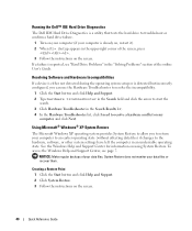
... Dell IDE Hard Drive Diagnostics is a utility that tests the hard drive to troubleshoot or confirm a hard drive failure. 1 Turn on your computer (if your computer to an earlier operating state (without affecting data files) if changes to the hardware, software, or other system settings have left the computer in an undesirable operating state. Creating a Restore Point 1 Click the Start button and click Help and Support. 2 Click System Restore. 3 Follow the instructions on using System Restore. To access...
... Dell IDE Hard Drive Diagnostics is a utility that tests the hard drive to troubleshoot or confirm a hard drive failure. 1 Turn on your computer (if your computer to an earlier operating state (without affecting data files) if changes to the hardware, software, or other system settings have left the computer in an undesirable operating state. Creating a Restore Point 1 Click the Start button and click Help and Support. 2 Click System Restore. 3 Follow the instructions on using System Restore. To access...

Quick Reference Guide
Page 44
... following message appears: Press any key to boot from the CD. 13 When the Welcome to Microsoft screen appears, click Next. 14 When the How will use the Drivers and Utilities CD while you are running the Windows operating system: NOTE: To access device drivers and user documentation, you must use this computer connect to continue. Windows XP installs the operating system components and configures the computer. 12 If...
... following message appears: Press any key to boot from the CD. 13 When the Welcome to Microsoft screen appears, click Next. 14 When the How will use the Drivers and Utilities CD while you are running the Windows operating system: NOTE: To access device drivers and user documentation, you must use this computer connect to continue. Windows XP installs the operating system components and configures the computer. 12 If...


