
Setup and Quick Reference Guide
Page 4
... Windows® XP 25 3 Specifications 29 4 Troubleshooting Tips 39 Using the Hardware Troubleshooter 39 Tips 39 Power Problems 39 Memory Problems 47 Lockups and Software Problems 48 Dell Technical Update Service 49 Dell Diagnostics 49 5 Reinstalling Software 51 Drivers 51 Identifying Drivers 51 Reinstalling Drivers and Utilities 51 Restoring Your Operating System 53...
... Windows® XP 25 3 Specifications 29 4 Troubleshooting Tips 39 Using the Hardware Troubleshooter 39 Tips 39 Power Problems 39 Memory Problems 47 Lockups and Software Problems 48 Dell Technical Update Service 49 Dell Diagnostics 49 5 Reinstalling Software 51 Drivers 51 Identifying Drivers 51 Reinstalling Drivers and Utilities 51 Restoring Your Operating System 53...
Setup and Quick Reference Guide
Page 8
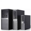
Back View 3 4 2 5 1 6 7 1 power supply check button 2 power supply check light 3 cover-release latch and padlock ring 4 security cable slot (security screw also an option) 8 About Your Computer 7 optical-drive eject button 8 optical-drive filler panel 9 flex bay (for optional floppy drive 10 USB 2.0 connectors (4) or memory card reader) 11 headphone connector 12 microphone connector Mini Tower -
Back View 3 4 2 5 1 6 7 1 power supply check button 2 power supply check light 3 cover-release latch and padlock ring 4 security cable slot (security screw also an option) 8 About Your Computer 7 optical-drive eject button 8 optical-drive filler panel 9 flex bay (for optional floppy drive 10 USB 2.0 connectors (4) or memory card reader) 11 headphone connector 12 microphone connector Mini Tower -
Setup and Quick Reference Guide
Page 10
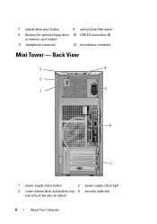
Desktop - Front View 1 2 3 4 12 11 10 987 6 5 1 power button, power light 3 optical-drive tray eject button 5 USB 2.0 connectors (2) 7 headphone connector 9 hard drive activity light 11 WiFi (optional) light 2 optical drive 4 Dell™ badge 6 microphone connector 8 flex bay (for optional floppy drive, memory card reader, or second 3.5-inch hard disk drive) 10 link integrity light 12 diagnostic lights 10 About Your Computer
Desktop - Front View 1 2 3 4 12 11 10 987 6 5 1 power button, power light 3 optical-drive tray eject button 5 USB 2.0 connectors (2) 7 headphone connector 9 hard drive activity light 11 WiFi (optional) light 2 optical drive 4 Dell™ badge 6 microphone connector 8 flex bay (for optional floppy drive, memory card reader, or second 3.5-inch hard disk drive) 10 link integrity light 12 diagnostic lights 10 About Your Computer
Setup and Quick Reference Guide
Page 13
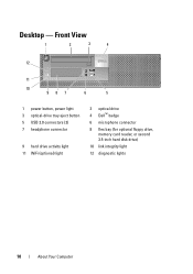
Front View 1 2 3 4 12 11 10 9 8 76 5 1 power button, power light 3 optical-drive eject button 5 Dell badge 7 microphone connector 9 hard drive activity light 11 WiFi (optional) light 2 optical-drive (slim-line) 4 slim-line flex bay (for optional floppy drive or memory card reader) 6 headphone connector 8 USB 2.0 connectors (2) 10 link integrity light 12 diagnostic lights About Your Computer 13 Small Form Factor-
Front View 1 2 3 4 12 11 10 9 8 76 5 1 power button, power light 3 optical-drive eject button 5 Dell badge 7 microphone connector 9 hard drive activity light 11 WiFi (optional) light 2 optical-drive (slim-line) 4 slim-line flex bay (for optional floppy drive or memory card reader) 6 headphone connector 8 USB 2.0 connectors (2) 10 link integrity light 12 diagnostic lights About Your Computer 13 Small Form Factor-

Setup and Quick Reference Guide
Page 29
Specifications NOTE: Offerings may vary by region. Processor Processor type System Information Chipset RAID Support DMA channels Interrupt levels BIOS chip (NVRAM) NIC Memory Type Memory connectors Intel® Core™2 Quad Processor FSB up to 1333 MHz Intel® Core™2 Duo Desktop Processor Intel® Pentium® Dual-Core ...
Specifications NOTE: Offerings may vary by region. Processor Processor type System Information Chipset RAID Support DMA channels Interrupt levels BIOS chip (NVRAM) NIC Memory Type Memory connectors Intel® Core™2 Quad Processor FSB up to 1333 MHz Intel® Core™2 Duo Desktop Processor Intel® Pentium® Dual-Core ...
Setup and Quick Reference Guide
Page 30
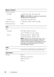
...card slot. Analog Devices ADI 1984A Integrated HD Audio PCI 2.3 PCI Express 1.0A and 2.0 SATA 1.0 and 2.0 USB 2.0 30 Specifications Memory (continued) Memory capacities 667 MHz 800 MHz Minimum memory Maximum memory Video Type: Integrated Discrete Audio Type Expansion Bus Bus type 512 MB, 1 GB, 2 GB, 3 GB, 4 GB, 8 GB..., 4 GB, 8 GB 512 MB for 667 MHz, 1 GB for 800 MHz 8 GB Intel® Q45 Graphics Controller up to 1759 MB video memory (shared) ATI Mobility Radeon™ HD3450 256M ATI Mobility Radeon™ HD3470 256M NOTE: Support for half-height video cards is available on Desktop and...
...card slot. Analog Devices ADI 1984A Integrated HD Audio PCI 2.3 PCI Express 1.0A and 2.0 SATA 1.0 and 2.0 USB 2.0 30 Specifications Memory (continued) Memory capacities 667 MHz 800 MHz Minimum memory Maximum memory Video Type: Integrated Discrete Audio Type Expansion Bus Bus type 512 MB, 1 GB, 2 GB, 3 GB, 4 GB, 8 GB..., 4 GB, 8 GB 512 MB for 667 MHz, 1 GB for 800 MHz 8 GB Intel® Q45 Graphics Controller up to 1759 MB video memory (shared) ATI Mobility Radeon™ HD3450 256M ATI Mobility Radeon™ HD3470 256M NOTE: Support for half-height video cards is available on Desktop and...
Setup and Quick Reference Guide
Page 34
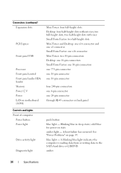
... blue in sleep state; amber 34 Specifications Connectors (continued) Expansion slots PCI Express Front panel USB Processor Front panel control Front panel audio HDA header Memory Power 12 V Power LAN on motherboard (LOM) Controls and Lights Front of computer: Power button Power light Drive activity light Diagnostic light Mini Tower: four...
... blue in sleep state; amber 34 Specifications Connectors (continued) Expansion slots PCI Express Front panel USB Processor Front panel control Front panel audio HDA header Memory Power 12 V Power LAN on motherboard (LOM) Controls and Lights Front of computer: Power button Power light Drive activity light Diagnostic light Mini Tower: four...

Setup and Quick Reference Guide
Page 42
... one until you find the bad one memory module is installed, try moving it to boot, inspect the CPU socket for damage. • If the problem persists, contact Dell (see "Contacting Dell" on page 66). 42 Troubleshooting Tips Contact Dell (see "Contacting Dell" on page 66). A possible motherboard ...a different DIMM connector and restart the computer. • If available, install verified working memory of the same type into your computer. • If the problem persists, contact Dell (see "Contacting Dell" on page 66). If the computer boots, add the peripheral cards back one by ...
... one until you find the bad one memory module is installed, try moving it to boot, inspect the CPU socket for damage. • If the problem persists, contact Dell (see "Contacting Dell" on page 66). 42 Troubleshooting Tips Contact Dell (see "Contacting Dell" on page 66). A possible motherboard ...a different DIMM connector and restart the computer. • If available, install verified working memory of the same type into your computer. • If the problem persists, contact Dell (see "Contacting Dell" on page 66). If the computer boots, add the peripheral cards back one by ...
Setup and Quick Reference Guide
Page 44
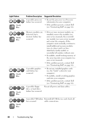
...Reseat all has occurred. drive or hard drive failure has occurred. Memory modules are detected, but a memory failure has occurred. • If two or more memory modules are installed, remove the modules (see "Contacting Dell" on page 66). A possible graphics card failure has occurred. ... service manual). • If the problem persists, contact Dell (see "Contacting Dell" on page 66). Suggested Resolution • Reseat the processor (see Processor information for your computer). • If available, install a working memory of the same type into your service manual and restart ...
...Reseat all has occurred. drive or hard drive failure has occurred. Memory modules are detected, but a memory failure has occurred. • If two or more memory modules are installed, remove the modules (see "Contacting Dell" on page 66). A possible graphics card failure has occurred. ... service manual). • If the problem persists, contact Dell (see "Contacting Dell" on page 66). Suggested Resolution • Reseat the processor (see Processor information for your computer). • If available, install a working memory of the same type into your service manual and restart ...

Setup and Quick Reference Guide
Page 45
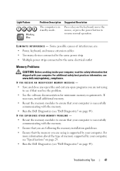
.../connector placement exist. • Ensure that no special requirements for your computer). • If the problem persists, contact Dell (see "Contacting Dell" on page 66). If the computer starts normally, continue to install additional memory modules (one module (see your service manual) and restart the computer. Troubleshooting Tips 45 Light Pattern Steady Blue...
.../connector placement exist. • Ensure that no special requirements for your computer). • If the problem persists, contact Dell (see "Contacting Dell" on page 66). If the computer starts normally, continue to install additional memory modules (one module (see your service manual) and restart the computer. Troubleshooting Tips 45 Light Pattern Steady Blue...
Setup and Quick Reference Guide
Page 47
... key on page 49). If necessary, install additional memory. • Reseat the memory modules to see "Dell Diagnostics" on the keyboard, move the mouse, or press the power button to the same electrical outlet Memory Problems CAUTION: Before working inside your computer, read ...that shipped with your computer. ELIMINATE INTERFERENCE - IF YOU EXPERIENCE OTHER MEMORY PROBLEMS - • Reseat the memory modules to ensure that your computer is successfully communicating with the memory. • Run the Dell Diagnostics (see if that your computer, see "Specifications" on page 49...
... key on page 49). If necessary, install additional memory. • Reseat the memory modules to see "Dell Diagnostics" on the keyboard, move the mouse, or press the power button to the same electrical outlet Memory Problems CAUTION: Before working inside your computer, read ...that shipped with your computer. ELIMINATE INTERFERENCE - IF YOU EXPERIENCE OTHER MEMORY PROBLEMS - • Reseat the memory modules to ensure that your computer is successfully communicating with the memory. • Run the Dell Diagnostics (see if that your computer, see "Specifications" on page 49...

Setup and Quick Reference Guide
Page 68
... Call for Help, 60 Internet connecting, 24 setting up, 24 L license label, 58 M media Drivers and Utilities, 57 operating system, 57 memory troubleshooting, 47 N networks, 21 connecting, 21 O operating system Dell Factory Image Restore, 54 media, 55 reinstalling, 57 System Restore, 53 Operating System media, 57 operating system product key, 58 P phone...
... Call for Help, 60 Internet connecting, 24 setting up, 24 L license label, 58 M media Drivers and Utilities, 57 operating system, 57 memory troubleshooting, 47 N networks, 21 connecting, 21 O operating system Dell Factory Image Restore, 54 media, 55 reinstalling, 57 System Restore, 53 Operating System media, 57 operating system product key, 58 P phone...

Setup and Quick Reference Guide
Page 69
...30 connectors, 33 controls and lights, 34 drives, 32 environmental, 37 expansion bus, 30 memory, 29 physical, 36 power, 35 processor, 29 system information, 29 video, 30 support, 59 contacting Dell, 66 DellConnect, 61 support (continued) online services, 61 regional, 61 technical support and ... Terms and Conditions, 58 transferring information to a new computer, 25 troubleshooting, 39, 58 blue screen, 48 computer not responding, 48 Dell Diagnostics, 49 memory, 47 power, 39 power light conditions, 39 program crashes, 48 programs and Windows compatibility, 48 restore to previous state, 53-54...
...30 connectors, 33 controls and lights, 34 drives, 32 environmental, 37 expansion bus, 30 memory, 29 physical, 36 power, 35 processor, 29 system information, 29 video, 30 support, 59 contacting Dell, 66 DellConnect, 61 support (continued) online services, 61 regional, 61 technical support and ... Terms and Conditions, 58 transferring information to a new computer, 25 troubleshooting, 39, 58 blue screen, 48 computer not responding, 48 Dell Diagnostics, 49 memory, 47 power, 39 power light conditions, 39 program crashes, 48 programs and Windows compatibility, 48 restore to previous state, 53-54...

Setup and Features Information Tech Sheet
Page 2
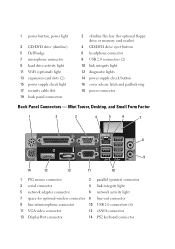
... 3 4 12 11 10 98 7 6 5 13 14 15 16 19 18 17 1 power button, power light 3 CD/DVD drive tray eject button 2 CD/DVD drive 4 Dell badge 5 power button, power light 6 CD/DVD drive 7 CD/DVD drive eject button 8 CD/DVD filler panel 9 flex bay (for optional floppy drive or 10... USB 2.0 connectors (4) memory card reader) 11 headphone connector 12 microphone connector 13 power supply check button 14 power supply check light 15 cover release latch and padlock ring...
... 3 4 12 11 10 98 7 6 5 13 14 15 16 19 18 17 1 power button, power light 3 CD/DVD drive tray eject button 2 CD/DVD drive 4 Dell badge 5 power button, power light 6 CD/DVD drive 7 CD/DVD drive eject button 8 CD/DVD filler panel 9 flex bay (for optional floppy drive or 10... USB 2.0 connectors (4) memory card reader) 11 headphone connector 12 microphone connector 13 power supply check button 14 power supply check light 15 cover release latch and padlock ring...

Setup and Features Information Tech Sheet
Page 3
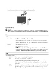
Front and Back View 1 2 3 4 12 11 10 9 13 8 76 5 14 15 16 19 18 17 5 USB 2.0 connectors (2) 7 headphone connector 9 hard drive activity light 11 WiFi (optional) light 13 expansion card slots (4) 15 power supply check light 17 security cable slot 19 back panel connectors 6 microphone connector 8 flex bay (for optional floppy drive, memory card reader, or second 3.5-inch hard disk drive) 10 link integrity light 12 diagnostic lights 14 power supply check button 16 cover release latch and padlock ring 18 power connector Small Form Factor-
Front and Back View 1 2 3 4 12 11 10 9 13 8 76 5 14 15 16 19 18 17 5 USB 2.0 connectors (2) 7 headphone connector 9 hard drive activity light 11 WiFi (optional) light 13 expansion card slots (4) 15 power supply check light 17 security cable slot 19 back panel connectors 6 microphone connector 8 flex bay (for optional floppy drive, memory card reader, or second 3.5-inch hard disk drive) 10 link integrity light 12 diagnostic lights 14 power supply check button 16 cover release latch and padlock ring 18 power connector Small Form Factor-
Setup and Features Information Tech Sheet
Page 4
1 power button, power light 3 CD/DVD drive (slimline) 5 Dell badge 7 microphone connector 9 hard drive activity light 11 WiFi (optional) light 13 expansion card slots (2) 15 power supply check light 17 security cable slot ...11 10 1 PS2 mouse connector 2 parallel (printer) connector 3 serial connector 4 link integrity light 5 network adapter connector 6 network activity light 7 space for optional floppy drive or memory card reader) 4 CD/DVD drive eject button 6 headphone connector 8 USB 2.0 connectors (2) 10 link integrity light 12 diagnostic lights 14 power supply check button 16 cover...
1 power button, power light 3 CD/DVD drive (slimline) 5 Dell badge 7 microphone connector 9 hard drive activity light 11 WiFi (optional) light 13 expansion card slots (2) 15 power supply check light 17 security cable slot ...11 10 1 PS2 mouse connector 2 parallel (printer) connector 3 serial connector 4 link integrity light 5 network adapter connector 6 network activity light 7 space for optional floppy drive or memory card reader) 4 CD/DVD drive eject button 6 headphone connector 8 USB 2.0 connectors (2) 10 link integrity light 12 diagnostic lights 14 power supply check button 16 cover...
Setup and Features Information Tech Sheet
Page 7
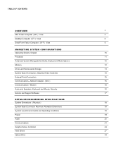
... slot. Video Type: Integrated Discrete Intel® Graphics Media Accelerator 4500 Microsoft Windows® XP: up to 1 GB maximum (shared system memory) Microsoft Windows Vista®: up to support.dell.com. one 3.5-inch external bay for half-height video cards is available on the monitor and the computer. Specifications NOTE: The following...
... slot. Video Type: Integrated Discrete Intel® Graphics Media Accelerator 4500 Microsoft Windows® XP: up to 1 GB maximum (shared system memory) Microsoft Windows Vista®: up to support.dell.com. one 3.5-inch external bay for half-height video cards is available on the monitor and the computer. Specifications NOTE: The following...
Technology Guide
Page 2
... ( DT ) View 6 Small Form Factor Computer ( S FF ) View 8 MARKETING SYSTEM CONFIGURATIONS Operating System, Chipset 10 Processor 11 Advanced System Manageability Modes, Deployment Mode Options 12 Memory 12 Drives and Removeable Storage 13 System Board Connectors, Graphics/Video Controller 15 External Ports/Connectors 15 Communications-Network Adapter ( NIC ) 16 Communications-Modem 16...
... ( DT ) View 6 Small Form Factor Computer ( S FF ) View 8 MARKETING SYSTEM CONFIGURATIONS Operating System, Chipset 10 Processor 11 Advanced System Manageability Modes, Deployment Mode Options 12 Memory 12 Drives and Removeable Storage 13 System Board Connectors, Graphics/Video Controller 15 External Ports/Connectors 15 Communications-Network Adapter ( NIC ) 16 Communications-Modem 16...

Technology Guide
Page 3
... diskless option to being the greenest PC company on the planet. DELL™ OPTIPLEX™ 960 TECHNICAL GUIDE DELL™ OPTIPLEX™ 960 Professional users seeking a sophisticated, powerful desktop need , with the OptiPlex 960's support for integrated wireless networking Time-saving tool-less cover removal ... built with 10% post-consumer recycled content Minimize power usage with Dell EnergySmart power management technology Environmental sensitivity with top-of-the-line processors, generous memory options, native support for Help Technology enabling end-user initiated remote support...
... diskless option to being the greenest PC company on the planet. DELL™ OPTIPLEX™ 960 TECHNICAL GUIDE DELL™ OPTIPLEX™ 960 Professional users seeking a sophisticated, powerful desktop need , with the OptiPlex 960's support for integrated wireless networking Time-saving tool-less cover removal ... built with 10% post-consumer recycled content Minimize power usage with Dell EnergySmart power management technology Environmental sensitivity with top-of-the-line processors, generous memory options, native support for Help Technology enabling end-user initiated remote support...

Technology Guide
Page 4
DELL™ OPTIPLEX™ 960 TECHNICAL GUIDE MINI TOWER COMPUTER (MT) VIEW FRONT VIEW 1 Hard Drive Activity Light 2 Link Integrity Light 3 Wi-FI Light (optional) 4 Diagnostic Lights 5 Power Button, Power Lights 6 Optical Drive 7 Optical Eject Button Drive 8 Optical Drive Filler Panel Flex Bay (for optional 9 floppy drive or memory card reader) 10 USB 2.0 Connectors (4) 11...
DELL™ OPTIPLEX™ 960 TECHNICAL GUIDE MINI TOWER COMPUTER (MT) VIEW FRONT VIEW 1 Hard Drive Activity Light 2 Link Integrity Light 3 Wi-FI Light (optional) 4 Diagnostic Lights 5 Power Button, Power Lights 6 Optical Drive 7 Optical Eject Button Drive 8 Optical Drive Filler Panel Flex Bay (for optional 9 floppy drive or memory card reader) 10 USB 2.0 Connectors (4) 11...


